WEEK 3
COMPUTER AIDED DESIGN


ASSIGNMENT DETAILS
Model (raster, vector, 2d, 3d, render, animate, simulate, ...) a possible final project.


INKSCAPE

Vector Drawing

I am most familiar with vector software like Adobe Illustrator which I use a lot to make concept sketches or to draw for machines in the Fab Lab but I have always wanted to learn more about Inkscape. At first glance, I find the Inkscape interface a little less intuitive but this is more likely an issue with my lack of familiarity with it. However, this is something I do consider when I am choosing a software to introduce kids to computer drawing. I have had success with software like Affinity Designer and Gravit Designer (which is free) and both are working iOS versions but lack some of the details that make working with machines easier. We always need to do a couple steps in Illustrator, Inkscape, or Corel Draw before sending drawings to a laser cutter. I know lots of artists and teachers using Inkscape and I have recently seen some of the unique features which make it a very interesting tool. Especially when you consider the active community surrounding it continually adding interesting features and add-ons.

Inkscape - Motor Block Concept Drawing

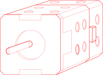
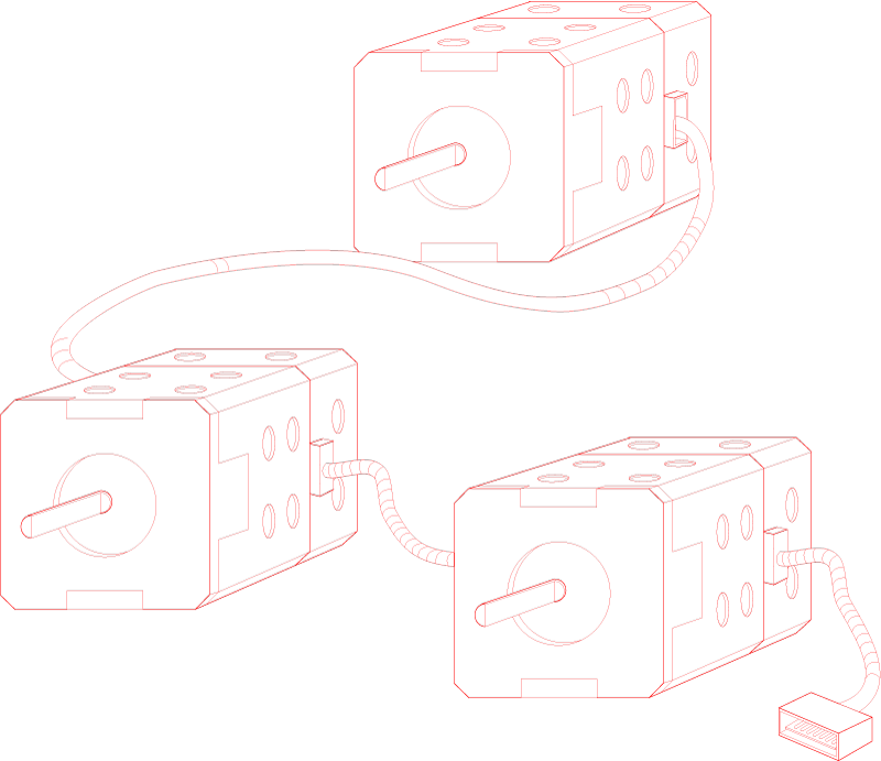
This is an initial concept sketch made with Inkscape to illustrate an idea for my final project. A stepper motor with a custom casing featuring mounting holes and a base containing a microcontroller running a version of Logo Programming.


I found this site useful:

Inkscape for Adobe Illustrator Users

Inkscape - Clone Tool

Clone Tool

My favourite feature of the Inkscape has been the clone tool There are ways to do similar things with Illustrator but Inkscape's cloning feature is fantatastic and can save a lot of time on 2d drawings where there are a lot of features that could change through iteration. Such as notches and press fit joinery.

Inkscape - Clone Tool

Shapes

At first I was frustrated by the way shapes had to be converted before you could edit the the paths by selecting Object to Path in the path menu. However, it was not without reason. This way, you can alter the curvature of teh vector line without breaking the object.

Inkscape - Clone Tool

Verdict

I'm just scratching the surface here but need to move on. I will try hiding Illustrator so that I am forced to use this tool more often. I think there are lots of secrets here to learn.


FreeCAD

I was excited to try FreeCAD. Especially after seeing Neil's demonstration of it. Firstly, it is free and capable. In many ways it looks simpler than Fusion but the interface is not as attractive. Why move from Fusion 360 which is also free for students? While I was not convinced it was worth using as a main tool it later proved crucial as a way to tranlate OpenSCAD files into a STEP graphics that Fusion 360 can read. More on that below. As with many of these tools I have been learning, the power is in their programability not their interface.
I decided I would also use FreeCAD to model a NEMA 17 Stepper motor as seen in the Inkscape concept sketches above.

FreeCAD - Nema 17 Body

As per my criteria for a new software tool, the accessibility factor of FreeCAD was appealing and I apreciate the statement below which I found somewhere in the About section of the software

FreeCAD
FreeCAD - Nema 17 Body

Sketching.

The sketching in FreeCAD is as good as in any CAD software. It was easy to make arrays which I needed for the mounting holes in the NEMA 17 model. Although the design is a bit too colorful for my liking, I like how the constraints and main features are featured as large icons above as this is how we build our parametric designs. What is more difficult with this software is getting around the different views and features. Something I think Fusion 360 has excelled at. I know there are a lot of features I could access to manipulate parameters which could be extremely useful but I did not bother with this for this short test. FreeCAD is easy enough to start drawing without going through a tutorial but this became trickier as I moved forward.

FreeCAD - Tool Bar

PROBLEMS WITH OVER CONSTRAINTS

I had a lot of problems with constraints. This is strictly to my in-experience. One thing I do not like about FreeCad is the palette of colors used to identify parameters or constraints. I certainly need to learn how to simplify my use of constraints but I find that red and green make a visual mess.


HIDDEN ISSUES

Not unlike any other CAD tool, it can be hard to locate areas where there is a break in a line, a misplaced node, or aduplicated line. Once I finally finished the sketch for the casing for the Nema 17 I wanted to extrude it I kept getting this warning:


It took me a while to diagnose where the broken face was but I finally found it and joined the broken points to close the shape.


With the shape closed, I was then I was able to extrude


My experience with FreeCad was an interesting one. It is a different way of working but I see lots of potential. Like Inkscape, it is just a matter of spending more time with the tool. I would love if they cleaned up teh aesthetics bit. In this case, I actually think it makes a difference on how accessible it is.


ANTIMONY

Had a lot of fun with this software! This could be from my previous experience with MAX MSP. I used the tool to model a NEMA17 motor which I will use in the assembly of my final project model. The shaft on the motor is combined with the rest of the motor preventing the option of doing interesting animations but I don't think I will be getting to that this time. In the future, I would make separate components.

Antimony - difference node

Difference

Made a square the size of a NEMA 17 using the square function which is found in the 2D section of the tools. I then used a triangle function to notch out a corner of the square using the difference node. Next Step: mapping this to the other corners.

Antimony - array node

Array

I needed to use an array function to map the triangle to the other corners of the square. This happens then before the difference node. Next Step: adding the z-height.

Antimony - extrude

Extrude

Now that I am happy with the initial 2d shape I had to add an extrude function which is under 2D-3D and extruded it 39mm which is the height of the Nema17.Next Step: adding the mounting holes.

Antimony - extrude

... Make Adjustments!

This was fun... to add the mounting holes to my model, I simply added a circle function and placed it next to the original triangles I used in the first step. I then plugged this into the same node on the array functionand voila!

Antimony - extrude

... Making the Motor Shaft

First I had to add a cylinder. Then I differenced a an elongated square to give it the flattened edge.

Antimony - extrude

Building the middle section

The indented core of the NEMA17 was made with a series of cubes that were used to cut a hole out of the body. Then I used the union function to add back a rounded cube inside the shape. At this point, the model looked complete enough for the time I had to spend on it.

Antimony - Moved the mounting holes but did not need to extrude?

...Making Adjustments

Once the middle core was completed the rounded cube that filled the center of the body blocked the mounting holes I had made so I removed the circles from where I had placed them at the beginning and moved them to after the core had been modeled. I'm not sure how this works because there is no extrude function after this. Instead of circles I would imaging I needed cylinders or an extrude function but oddly it is still punching the holes through the body without it.

Antimony - final model in Fusion 360

Exporting

I attached the export function and then opened it in Fusion 360. I noticed first that there was a glitch. One of the corners had an element that needed to be adjusted. The other aspect was that the shaft was missing. I realized that I did not attach it to the overall model.


Antimony - extrude Antimony - Mistake Antimony - extrude


MAPPING THE PARTS


OPENSCAD

I had a lot of fun with OpenSCAD. It was easier to get into than I expected. I decided to model a NeoPixel grid from Adafruit. I went to the page and took note of all the specs and schematics for the NeoPixels themselves. You can find all the information on Adafruit provides everything you need to know about NeoPixels. Get it HERE.

Here is a link to my project file: amathewson_8x8_NeoPixelGrid.scad

The Panel


module neo8x8(){
color("black") cube([71.12,71.12,1.6]);

MAKING A PIXEL

The following code is used to make a single NeoPixel including the SMD pins on the bottom.

   
       module pixel(){
        union(){
    
        difference(){
        translate([0, 0, 1.6]) color("white") cube([5,5,1.6]); 
        translate([-.5, -.5, 1.4]) cube([6,1.5,.35]); 
        translate([-.5, 4, 1.4]) cube([6,1.5,.35]); 
        translate([2.5,2.5,2.5]) cylinder ( h=5, r=1.8, $fn=100);

        }
        translate([0,0,1.6]) color("white") cube([.4,5,.5]);
        translate([1.6,0,1.6]) color("white") cube([.4,5,.5]);
        translate([3.1,0,1.6]) color("white") cube([.4,5,.5]);
        translate([4.6,0,1.6]) color("white") cube([.4,5,.5]);
        }
      }

I started by making a simple cube then I cut out a circle halfway through. Next I made notches in the bottom to reflect where the SMD traces are. Although the overall size of the NeoPixel is modeled on the dimensions in the schematic, the SMD pads are not spaced are estimated. If I use this model to map traces, I will have to double check all the spacing to be sure.


MAKING AN ARRAY

   
      module rectangular_array (rows, cols, distance){
        for ( i = [0:1:rows-1]){
            for ( j = [0:1:cols-1] ) {
            translate([distance*i, distance*j, 0])
            children();}
                       }
       }

ADDING DETAILS

To make teh model a bit more realistic, I included the IO pins to reflect data, GND, & 5v.

module iohole(){
        difference(){
        translate([-.4,3,-.1]) color("gold") cylinder(h=1.75, d=2, $fn=100);
        translate([-.4,3,-.2]) color("gold") cylinder(h=3, d=1, $fn=100);
    }
    }
        translate([8.9,0,-.01]) iohole();
        translate([8.9,3,-.01]) iohole(); 
        translate([8.9,6,-.01]) iohole();
        translate([63,65,-.01]) iohole();
        translate([63,62,-.01]) iohole(); 
        translate([63,59,-.01]) iohole();


FUSION 360

Having the most experience with Fusion 360 out of all of these CAD tools, I decided a good test would be to input some of the above designs and see how well the programs interact.


Importing OpenSCAD Model

Fusion 360 does not natively import .scad files. Stl's are hard to work with. Reading this forum discussion discusses the option of converting the .scad file into a .step file which is a widely used data exchange format that I know little about. Luckily, FreeCad can do this so I did not need to download any new programs. I was able to export the model with colors.

STL File

FreeCAD - Exporting STEP file


Importing .STEP File

Importing into Fusion 360 was relatively easy. It took longer than I expected but it worked nicely.


Here is a render of a NepPixel block that might become module in my final project