WEEK 6 - 3D SCANNING & PRINTING

ASSIGNMENT DETAILS
Group assignment: test the design rules for your 3D printer(s). Individual assignment: design and 3D print an object (small, few cm) that could not be made subtractively 3D scan an object (and optionally print it).

I decided that for the 3D printing week that I would make a cage with a ball in it which later turned into a noise maker. I tried several printers. My main printer at the LCC Fab Lab which échoFab also has is a Ditto Pro from Tinkerine. Targeted as a printer for education this was a very popular machine in Québec but the company has not updated it since 2015 and it is missing many of the more common features you see today. It is capable of very nice prints but it can be finicky by today's standards. The other printer I tried was an Ultimaker Go which ended up being the machine I used for this assignment.


GROUP ASSIGNMENT

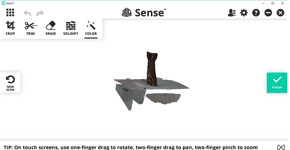
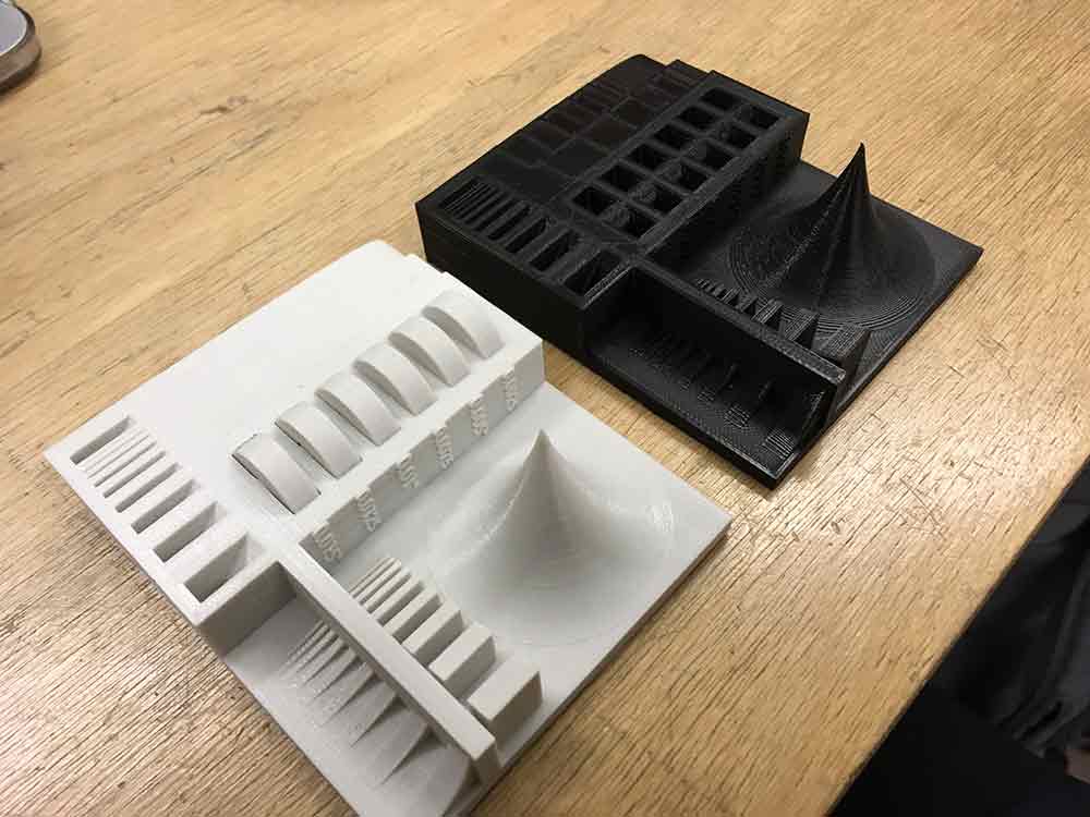
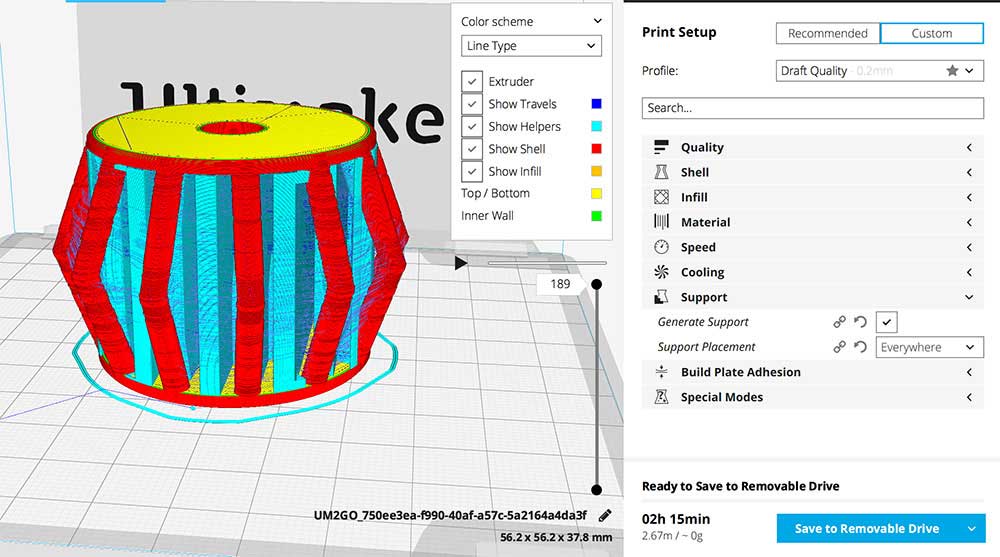
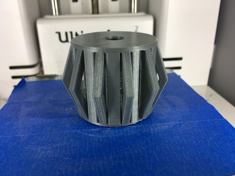
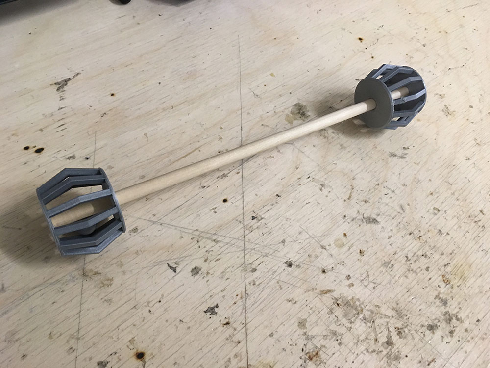
We chose to do the the 3D Printer Tolerance Test by user amandaghassaei. This test is designed with features that really push your printer. As a group, we decided to try this test on different printers and then compared them. I printed one on the Ditto Pro and Marc did a version with the Ultimaker 3i> and did some measurement tests. You can see his documentation HERE.


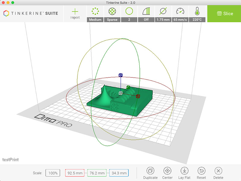
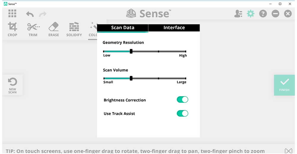
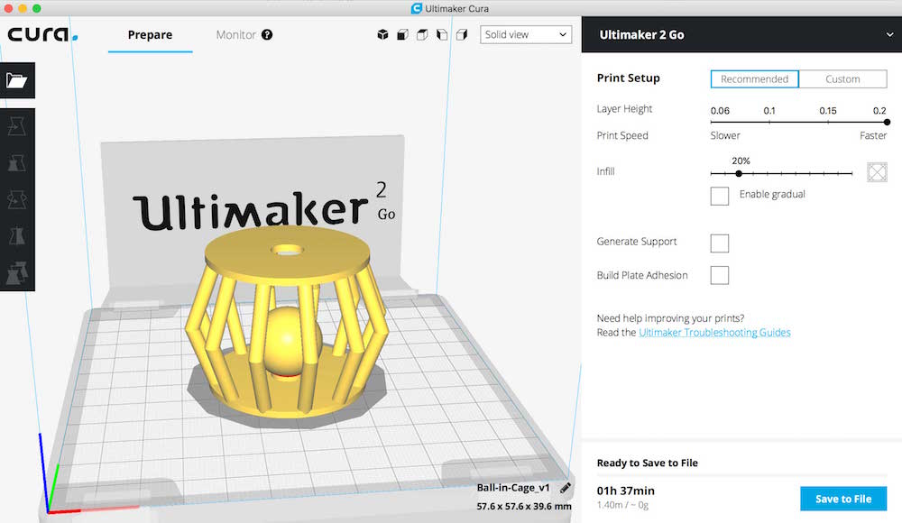
I loaded the .STL file into Tinkerine Suite slicer software and printed with the test with these settings:

---> Medium quality
---> Sparse infill
---> Wall thickness 2

In the advanced settings you can see more detail as to what is happening in the presets.


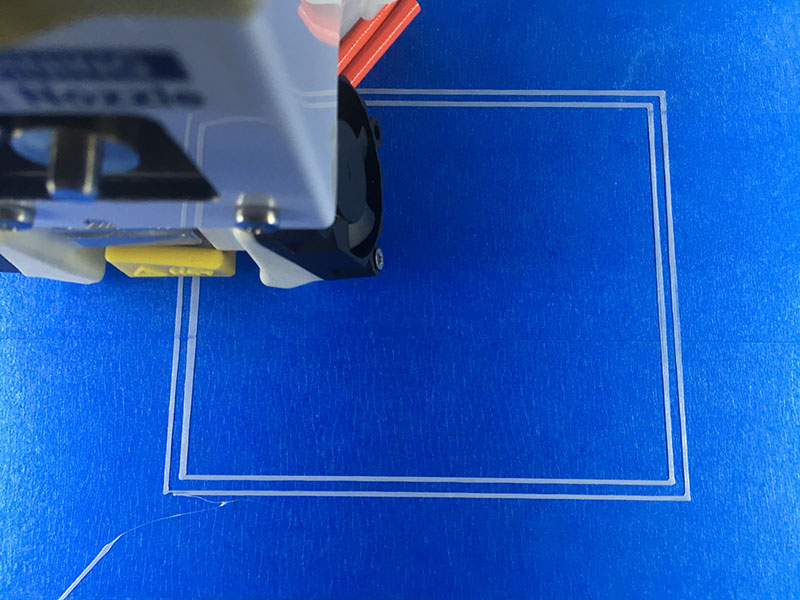
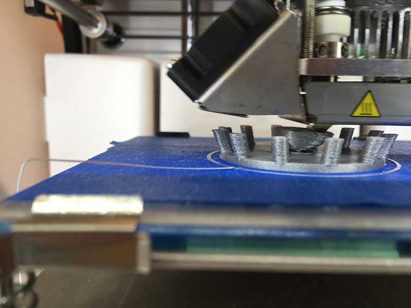
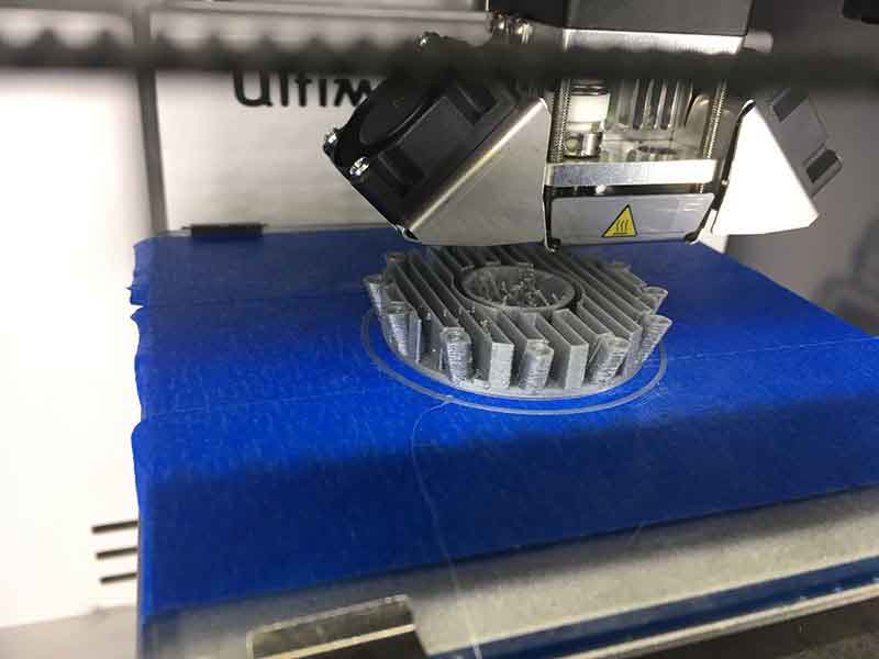
The printer was set to do 2 passes before starting to print the object. In this phase you can check the bed settings and filament flow. You can see from the following images that that the bed was not level. One corner, the filament sits on top and you can see spaces between the traces. The other side you can see that the filament is more translucent which means it's pressing to tightly against the bed.


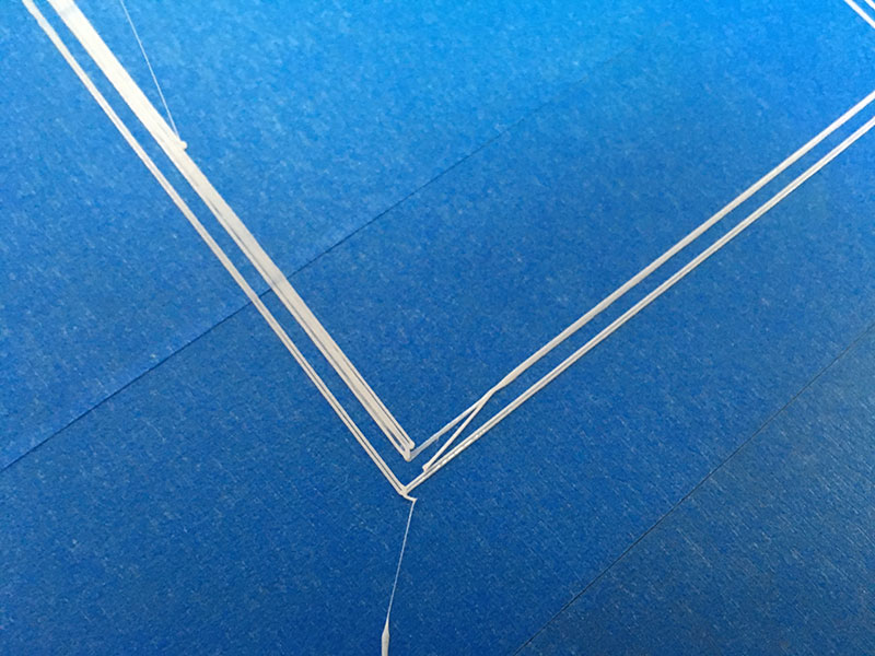
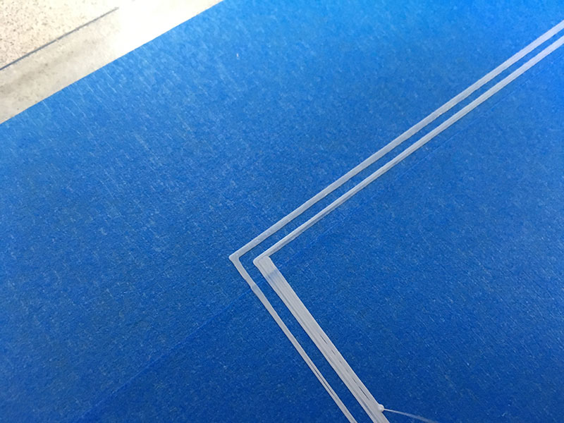
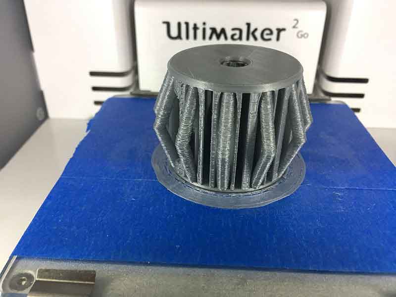
The next two images show the differences between an uncalibrated bed and a calibrated bed. you can see the first one is the unleveled bed, the second is leveled. I would say on further review, the second is not perfectly level either but I thought close enough.


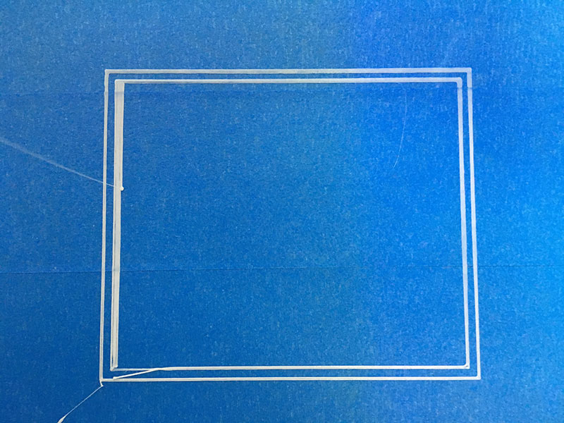
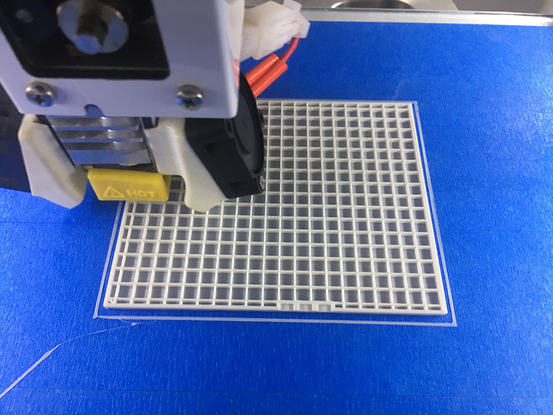
The next image demonstrates 18% infill. I need to spend a lot more time working with the custom settings. I really want to learn how to play with teh direction of the filament in relation to the shape. This was not possible with Tinkerine Suite slicer.


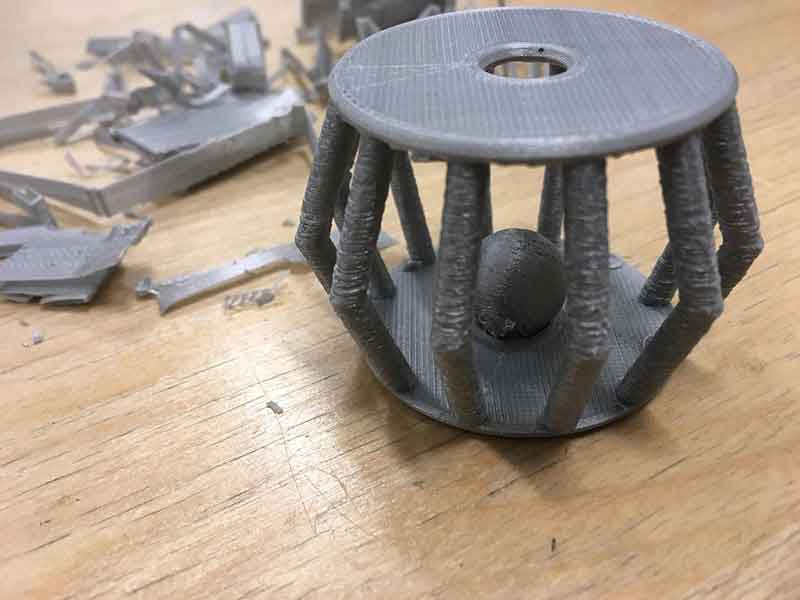
At first glance the final prints looked good but you can see some lifting on one of the corners. This may have been a result of the bed not being perfectly level, it could also be other adhesion issues like temperature.


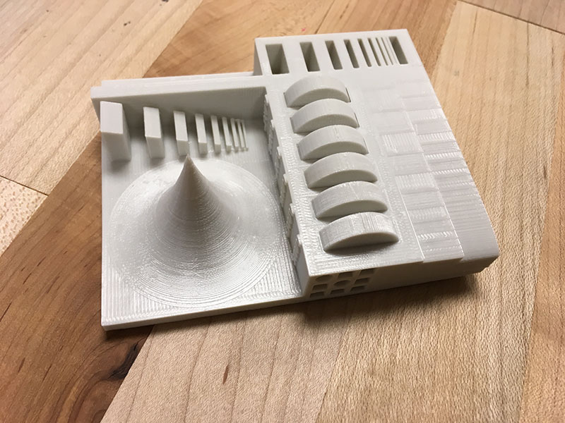
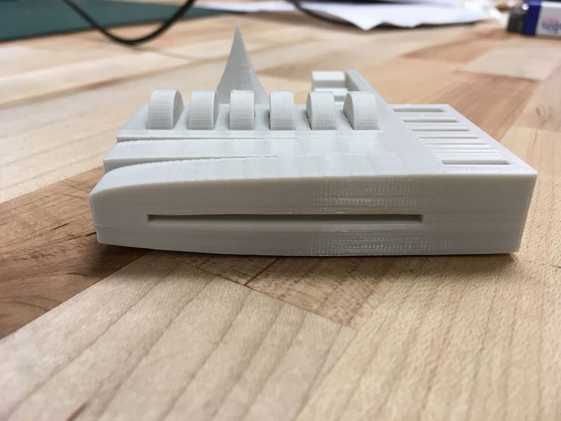
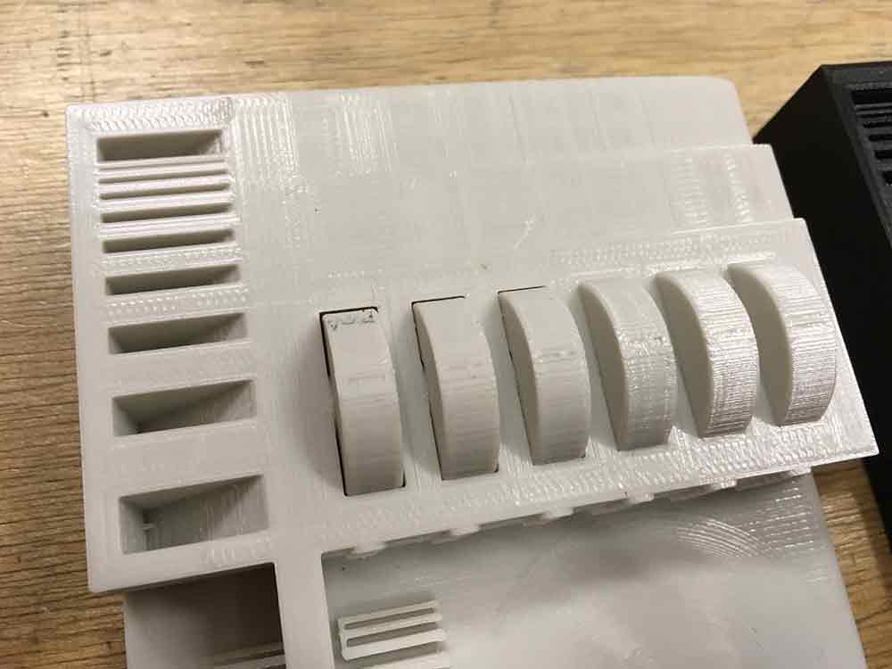
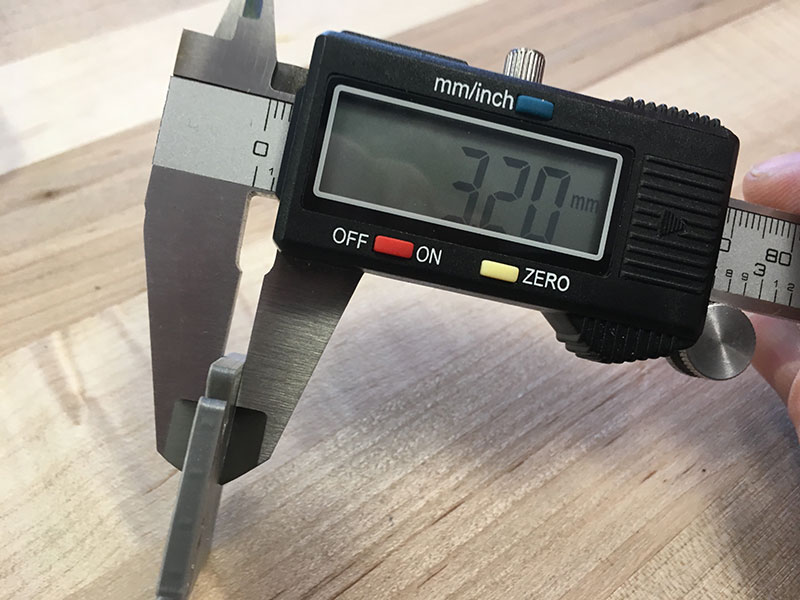
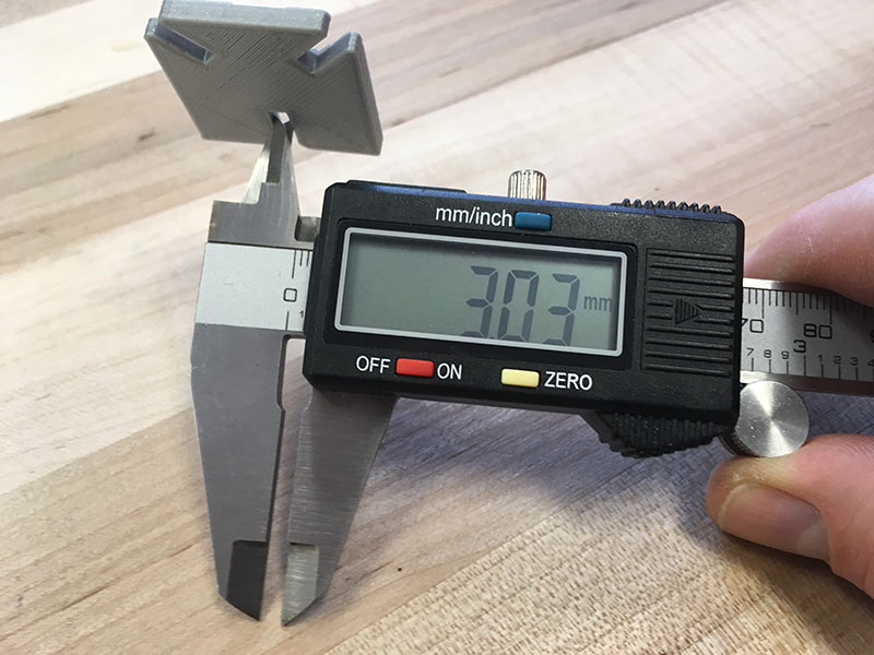
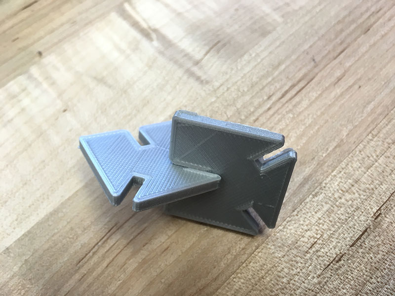
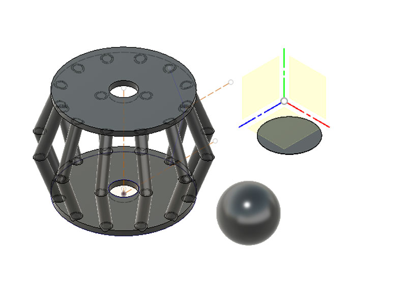
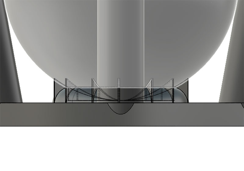
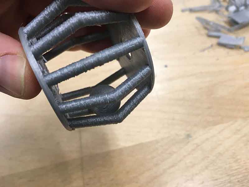
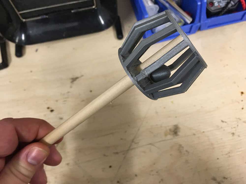
It was a bit unclear what specifically I needed to evaluate. I realized I did not spend enough time doing research on this test. I will go back when I have more time. There are two versions of the print. The one I did, the wheels are printed in the object. I think they are supposed to turn. In the Ditto print (white filament) the wheel on the far left looks like it can be broken free. There is a small gap around the object. It was impossible to move. Marc printed the version where the wheels are separate. The cone looked good. Very sharp. I need to compare this test with super fine settings.


3D PRINTING


For 3D printing my object, I focused solely on using the Ultimaker Go which is discontinued. It was a great idea. I was able to pick on up second hand and I wanted to test it out. The idea in our lab is that we could eventually loan it or take it places provided the users have proven they can use it effectively. Before printing my object, I did another tolerance test. I took the press fit design I made in week Week 4 and wanted to measure the spaces.


There was a fair bit of deviation from the Fusion 360 model and the 3D print. I space in the notch is only off by .07 mm but the height is off by .2 mm! I did not take a photo but this print was done on a raft. It is possible, that added some thickness. However, at the end of the day, it still worked as an effective press fit.


3D PRINTED NOISE-MAKER

My goal for this as to using Fusion 360 to create a bird cage like shape with a ball in it. Then to put a dowel through this so that you can shake it and make noise.


---> Designing the ball-in-cage

I first made the bars for the cage. I took a line and created a pipe around it.


To complete the cage I made a circular pattern using the bar I had just design and then created a floor and a cieling. I put a hole through the floor and cieling to match the diameter of the dowel I was going to use which was 9.18 mm. I made the hole 9.2 mm. Lastly, I made a sphere and positioned it in the middle of the design.


My intention was to try and print this without supports by building a support structure for the ball to sit on.


I used Cura as my slicer. My first prints were all in draft mode. 20% infill and prioritized speed over quality. It was already a big enough print that I didn't want to waste time testing out ideas.


---> printing - version 1


Luckily, I was able to see that this was not going to work as the support was not good enough. As much as I would have liked to finess this idea, I abandoned it for the moment to try working with supports.


This is the same design but with supports. I added supports everywhere and I chose Line as the type. This is already a 2hr print.


The print went fine and everything looked as it should. I could see that the ball had enough support however, it looked pretty messy in the middle.


The small features of the bars looked pretty ratty at draft resolution but I was happy to see that the print was successful. I found the support material was surprisingly easy to remove. It was much easier to remove than what is produced using the Ditto's Tinkerine Suite.


It did not take long for one of the cage bars to break. I went back to the drawing board to make a stronger cage. I also decided to go with square shaped bars. It would likely look a little better at lower resolutions. I also decided to float the ball in the middle of the cage. The thought behind this was that it might make it easier to remove the supports. The supports should hold the ball in mid air as it is prined.


---> printing - version 2


Chose a normal setting which was 0.15 mm layer height and pushed the print to 3H. I made a few changes to the settings:

---> Infill 30%
---> support angle 45º
---> temperature 210

NOTE:I was going to print this version at échoFab on their Ultimaker 3 but the print was too long so I ended up printing on the Ultimaker Go.


The print went fine. It looked a lot cleaner and stronger.


I pushed the dowel through. It was tight enough. Even though the space was .02 mm bigger, there was enough pressure to make a tight fit suggesting some shrink in the material. This worked in my favor. I did not do many tests before trying. I printed a second one to put on the other end of the dowel. It sounds pretty good too!


This was a playful object, perfect for fidgeting. My students dropped it and it seemed a piece of the cage broke everytime. I would glue them back to keep the object useable. The real fix is a re-design, maybe a stronger material, more infill. Fun little project though.

Reflection: I guess this shape could be done using subrtative processes although it would be very hard to do as one part. It would also be hard to get the square angles of the cage on the inside. The question would be why bother making this in one part? That being said, the geometries of this shape are not as complicated as they could be to truly demonstrate the more unique abilities of additive manufacturing.

Unlike milling or using a subtractive cutting process, you are less bound by the direction of the tool. The process of slicing opens up a world of intricacy for experienced 3d modelers. Additive manufaturing is more bound by the tolerances of the material being added. That is to say, how that material can be layered. When you slice an object you can make holes within objects, you can slowing twist shapes around themselves. As my 3d modeling skills improve, I will start to experiment more with more complex geometry.


3D SCANNING


I'm not going to lie, this was my least favorite Fab Academy task. Not because I don't see the huge benefits of 3D scanning. Just because I struggled to get a good hold on the technology. I used échoFab's Sense Scanner from 3D Systems. No doubt this could be a good tool but I struggled to get the images I was looking for. Maybe I just did not know what I was looking for. Also, there must be a better way to scan around objects than having to hold a laptop in one hand. I have seen rigs and tablet tables people wear. I guess a long USB 3 extender might do the job. Anyways, this is what I had. I used to make a living as a documentary filmmaker.

NOTE:This was just a photo op to demonstrate the laptop in one hand, scanner in the other. The setup of my objects were more organized.


Our instructor, Mathieu, challenged me at first. "I'm always up for a challenge!", I said. He asked me to scan one of his sliced wood sculptures. After 10 tries, adjusting the sensitivity on the scanner, trying different the placements of the object, and using a rolling chair, etc... I was only capable of scanning 3/4 of the shape. It kept bouncing out of sync. The only thing at this stage was to go to a studio with solid background, or trying a smaller object.

>


I wasn't ready to give up. I went for a smaller version of the same kind of object. It was a bit easier and managed to get a half decent scan, but the complexities of this shape seem to confuse the scanner in this environment.


The scanner kept getting confused on one side of the object. I tried re-orienting my scanning angle but still the same angle would go out of sync.


Frustrated, I took a break to get a coffee... and a donut! The donut was the first to be scanned. This is probably not the right scanner for the donut job. Too much detail in the sprinkles but I was able to get most of the shape. If I had access to a desctop scanner with a rotating base, I would use this.


I ended on the easiest object... the coffee! I was able to get a full scan. Still lots of anomalies but I think a software like Meshmixer should be abe to fix those. Still, I just don't know how much detail to expect before using an editor to clean it up.


Later, I went back to try and scan one of the press-fit objects I tried earlier. This time, I turned the detail down whcih made it easier. I also moved it to a white surface. I wasn't getting the details hoping for. The 3D Sense scanner software is very simple. I was expecting more features to be able to control. After selecting the kind of scan I wanted to do, in this case I chose OBJECT I had to access the advanced settings. The advanced settings really should be baseline settings. There is little control beyone a few sliders. I chose a lower resolution and a smaller scan size which seemed to help my process. It was less finicky but clearly lacked some detail.


I used the Trim tool to get rid of the base area that was included in the scan. It would be nice if you could make more complicated paths but I guess this has a lot to do with the way the tool operates in 3d space.


Here is the finished scan. It was easier to take but but I still find the tool quite cumbersome.


3D scanning can bring the physical world into a virtual space. In the Fab Lab context, 3D scanning allows us to duplicate objects that exist only in the physical space. The disadvantages to 3D scanning for me is largely due to the precision required to control a scanner. Expensive units will use dots to help locate the objects, you can also use a rotating bed. 3D scanning can accurately represent technical objects but there seems to be a real skill to being able to do this with handheld devices. I look forward to trying onther kinds of scanners in the near future.


ASSIGNMENT FILES

---> Ball Cage Model - .f3d
---> Scans - .mtl


Creative Commons License
This work is licensed under a Creative Commons Attribution-NonCommercial-ShareAlike 4.0 International License.