GETTING STARTED
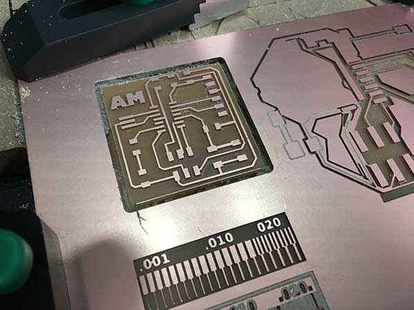
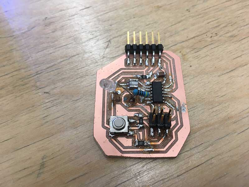
The first board I made for this assignment followed closely the version created by Loes Bogers(Fab Academy '2015)
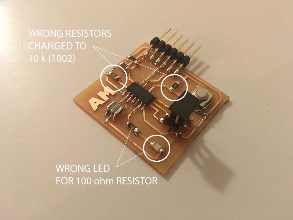
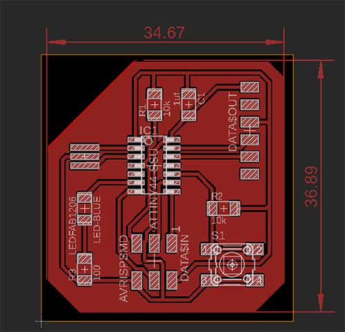
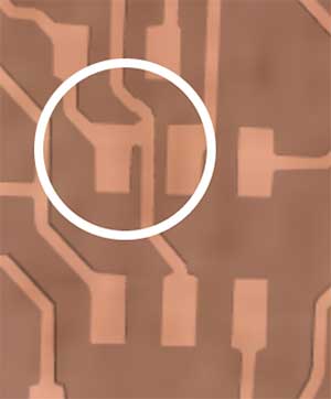
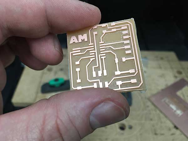
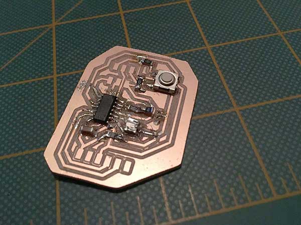
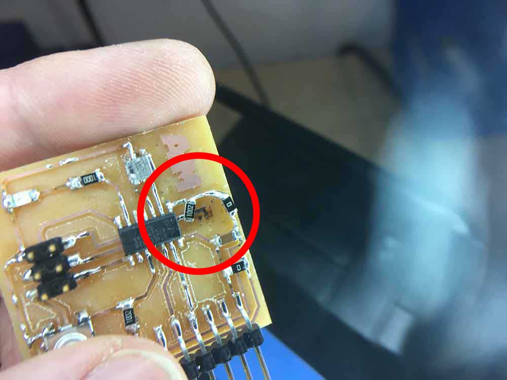
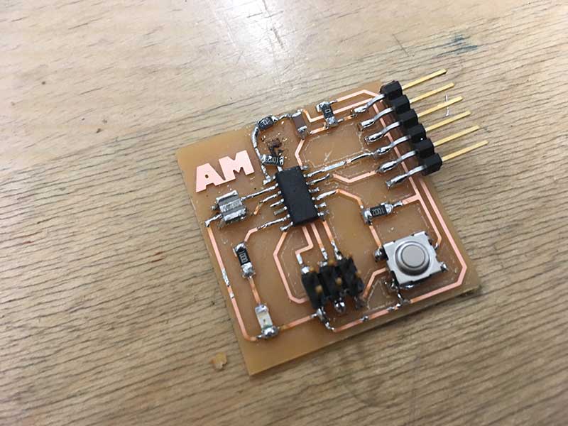
I was very proud of the look of this board. Cleanest yet. But... I messed up the resistors. I had to desolder and change them for the right ones. In doing this, I burnt some traces and had to get creative using a 0 ohm jumper. This is what the final board looked liked.
Not only did I accidentally put the wrong resistors on, I put a 100 ohm resistor for the LED, thinking it was a blue LED. The LED is an orange one and actually requires 150 ohm or higher resistor.
---> choosing an LED & resistor
Ohm's Law: V = I x R /// V / I = R
Blue LED - SMD 1206
---> Part number: 160-1889-1-ND
---> ATTiny pin = 5v
---> V needed for LED = 3.3v
---> V drop = 1.7
---> 1.7 / 0.02a = 85 ohm
The board is sending 5v out of PA7 / pin 6 of the ATTiny that the LED is connected to. The LED needs 3.3v. We need to loose 1.7v at 20ma to protect the LED. This means we need a minimum of an 85ohm resistor coming from the pin of the ATTiny44 to the LED. We can round up to use a 100 ohm resistor. In this first board, I accidentally used an orange LED. The requirements for the orange LED are as follows:
Orange LED - SMD 1206
---> Part number: 160-1403-1-ND
---> ATTiny pin = 5v
---> V needed for LED = 2v
---> V drop = 3
---> 3 / 0.02a = 150ohm
My board only has an 100ohm resistor for the orange LED that was put on it by mistake. It works fine but the LED will eventually wear down. It should be changed to a higher resitance or add another 100 ohm resistor.
---> making a schematic in Eagle
Working with Eagle has been a lot of fun. I don't know if I will ever need to use more than just a fraction of what it can actually do. I have found that there are only a few basic features that I need to design the boards I have been making.
In the schematic view here are the tools I have been using most:
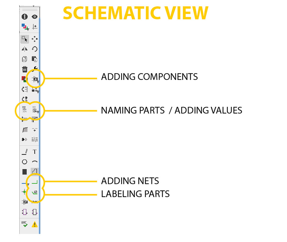
---> Adding components - use this to add the elements that you need from the Fab Lab Eagle Library. I learned how to do that by following the Fab Academy tutorialHERE.
---> Naming parts - in the schematic view you need to name the parts that you add. If not, you will have generic names that are impossible to keep track of. This step is done once they have been labeled with the label tool.
---> Adding values - it is also important to lable the values of your components. Especially resistors and capacitors.
---> Adding nets - the net tool is bsically how you wire your board. You add nets between the components or between the component and your label. This is how you know how to connect everything once you get to the board view---> Labeling parts - the label tool is one of the most important. You can identify what the different pins are and where you nets are connected to. You need to name your labels once they are done.
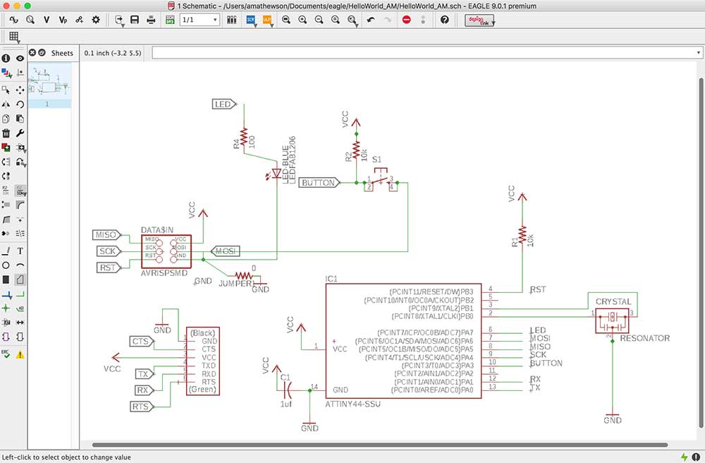
The finished schematic for this board looked like this:
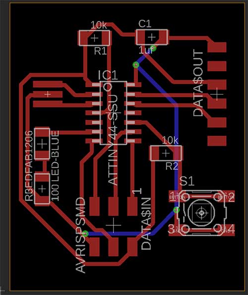
---> designing a board in Eagle
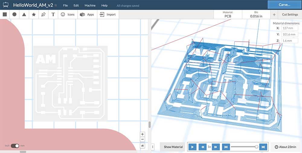
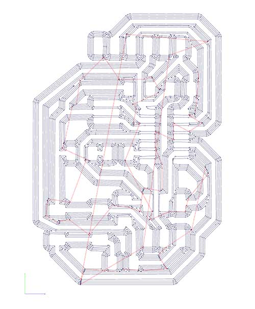
Designing a board in Eagle is kind of like working on a puzzle. There are limitations to what you can do and you have to work around them. Like in the schematic view, there were only a handful of tools I actually used for this project.
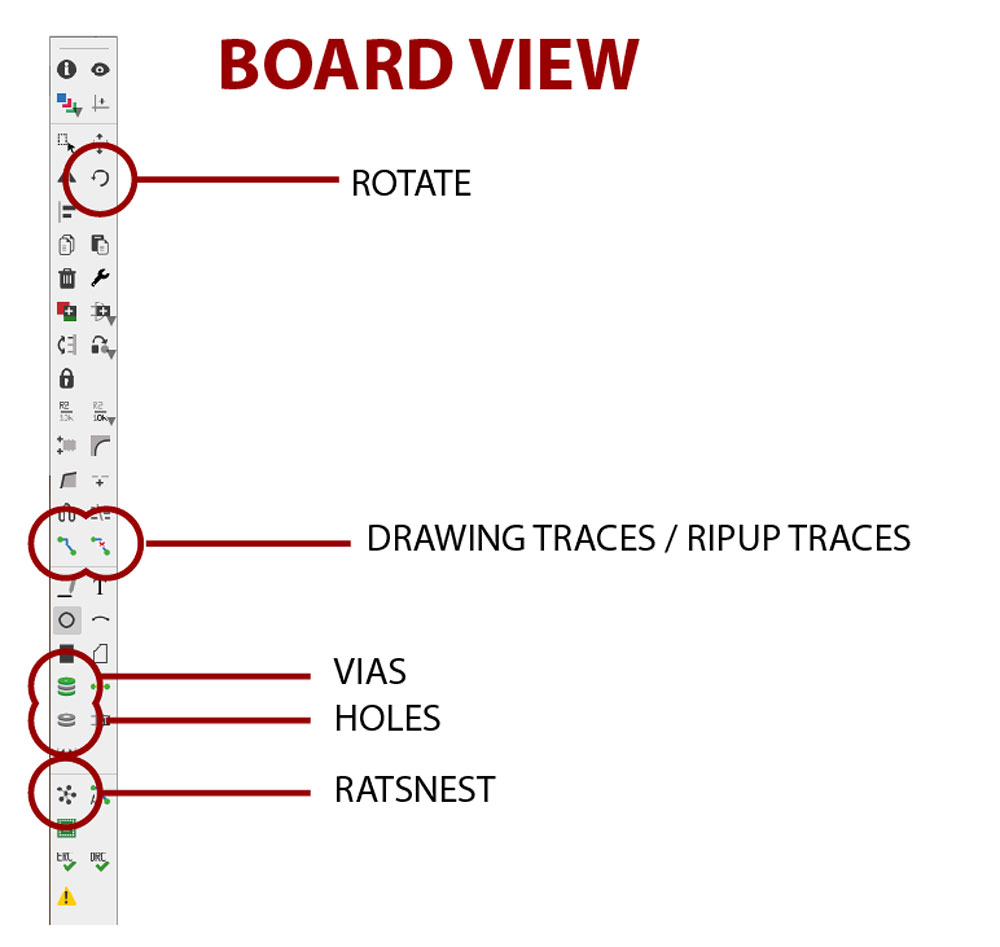
---> Rotate - you end up rotating your parts to find best way to design your traces.
---> Drawing traces - the trace tool is at the heart of this process. I tried autotracing and hated it. I prefer manually tracing them.
---> Ripup - the ripup tool is essentially an eraser for your traces. If you need to start your board over you can type RIPUP ; in the command bar.
---> Vias - I never used vias but if you use them it certainly can help your layout.
---> Holes - you can drill holes in your board. I use this later on in Fab Academy to mark where I want to make to pass wires in my final project.
---> Ratsnest - the ratsnest tool is useful to clean up your board as you move items around. It will direct you to the closest GND or VCC and help you visualize when your parts are properly connected using airwires.
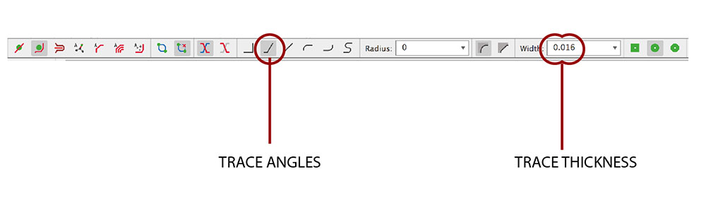
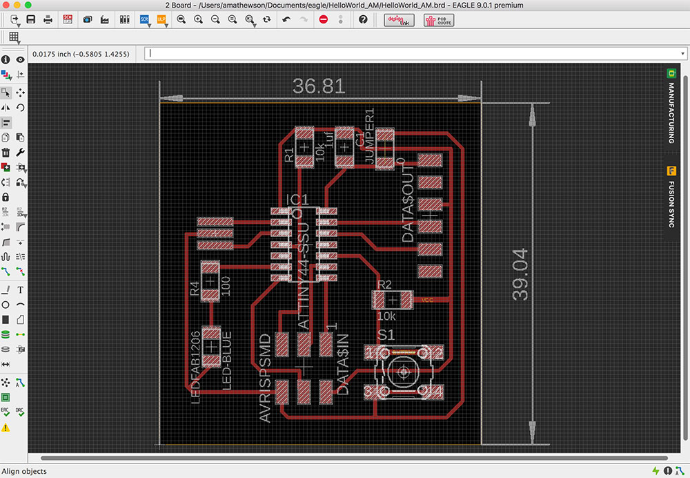
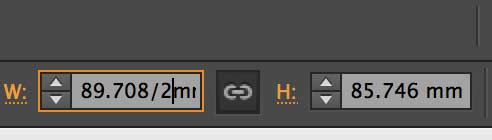
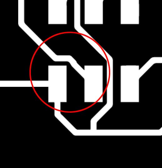
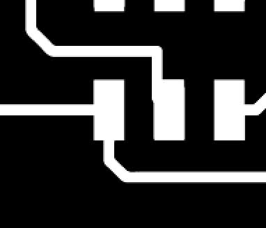
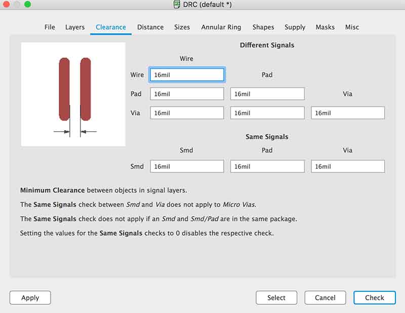
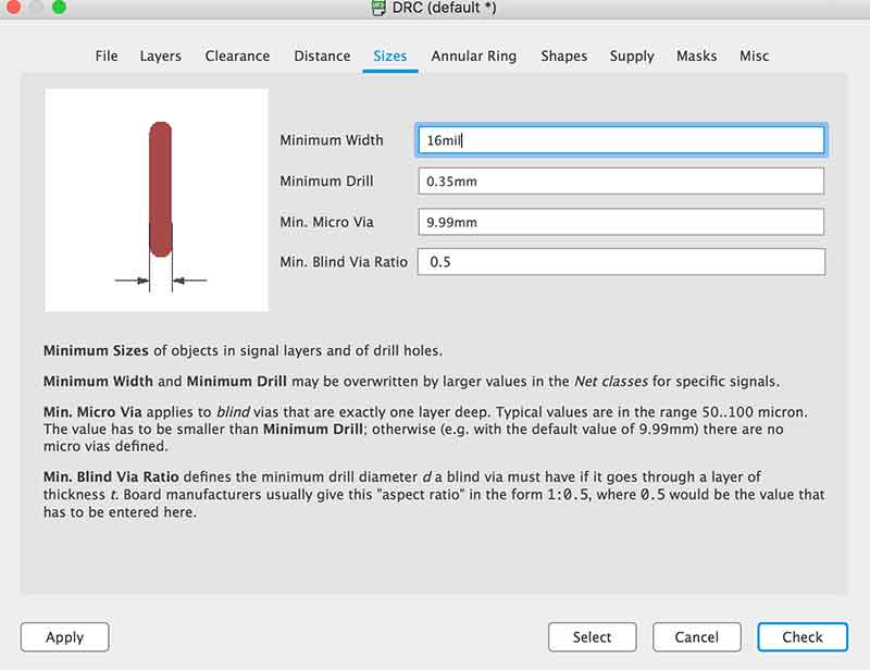
When using the traces tool you have options to help control how it behaves. I would often change the way the traces behaves by adjust the angle that it prefers. By far, the most important element here is to set your trace width. I found 0.016" to be the best. It matches size of the milling bits I use. When setting the other design rules by selecting the DRC tool in the Tools menu, I set anything that has to do with basic spacing of the traces to 16 mil. This seemed to work out nicely.
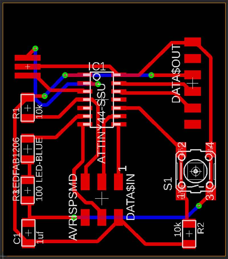
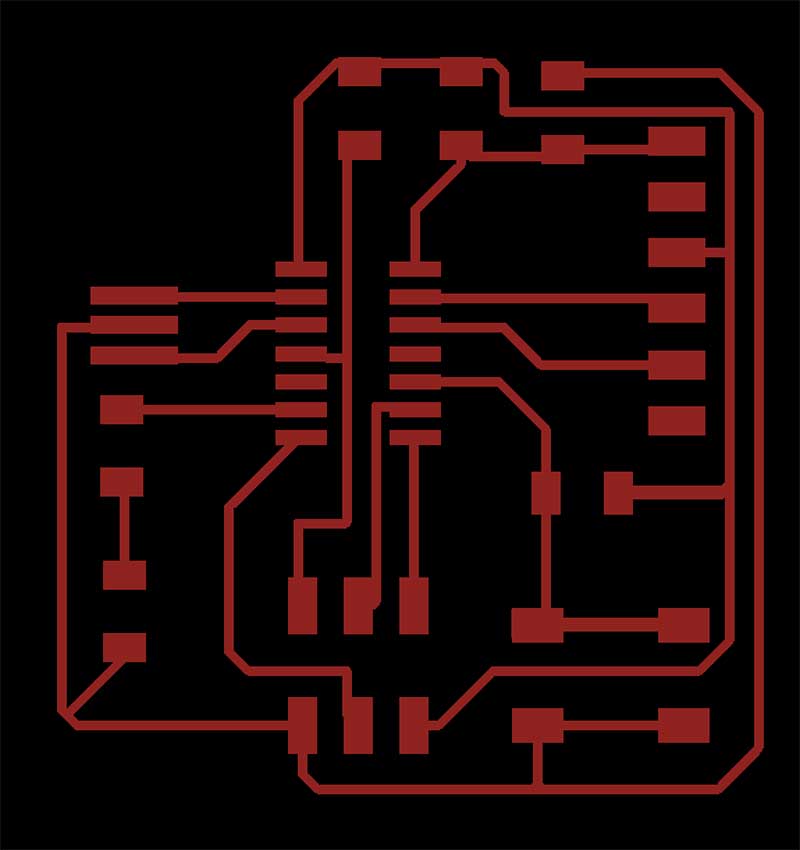
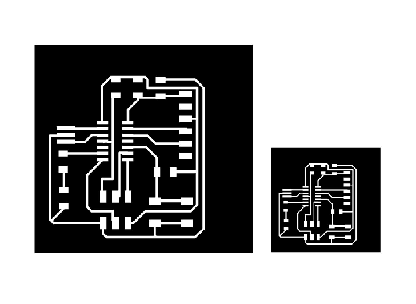
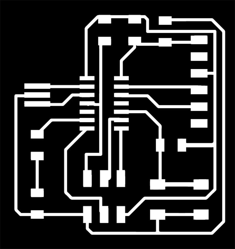
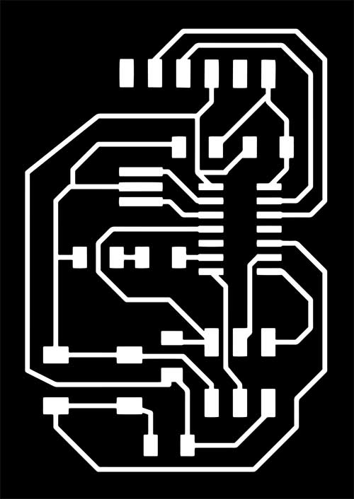
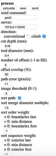
The last step is to export the board as an image. As was done in the Electronics Production week, I selected only the top traces in the layers menu, then exported it as an image with the following settings:
---> PNG
---> monochrome
---> 500 dpi
---> full area