Final Project Presentation
Design of a Dobson Telescope and Guiding System
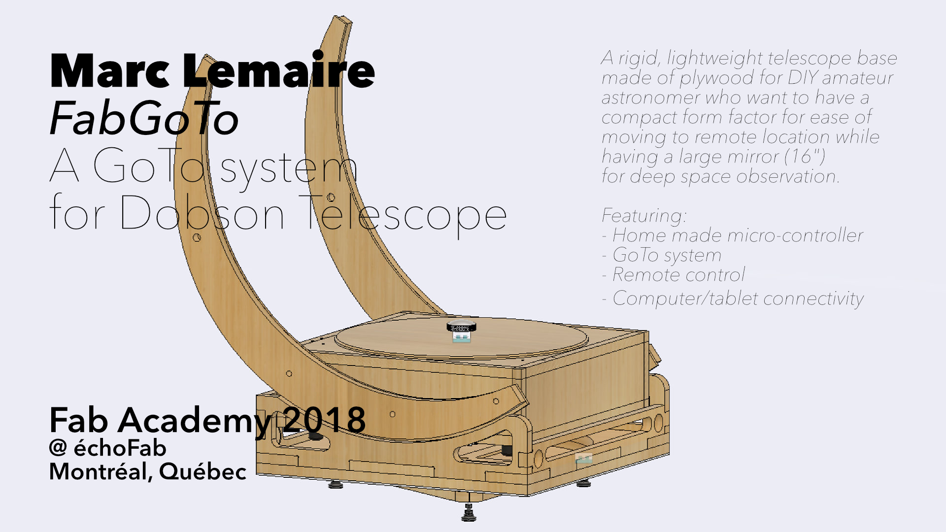
The starting point of my project is a reference book written by Alber Highe Engineering, Design and Construction of Newtonian Telescopes. This title is a cookbook about making a Dobson style of telescope. The main advantages for this style of telescope are lightweight, superlative technical specifications and ease of use. It describes a process of construction that can be applied from small to very large telescopes. However, there is no chapter about building the motorized part for tracking stellar objects during long observation nights. My project is to design this important part and digitize the fabrication process with parametric design.
This project will focus on the design of the Lower Optical Assembly (LOA) and the base. The most costly item, the mirror, will be simulated with a dead weight that will not be an electric car but probably a cement block.
The Presentation
I presented my project on the 20th of June 2018. As usual, I was very nervous because of all the problems that I faced, there's wasn't much to present. I've made the design of the Base, the Rocker Base and the Lower Optical Assembly during late winter/early spring. I made the Rocker Base during the Make It Big week and had the intention of finishing things up for June but that WAY overly optimistic schedule went down the drain with the machine design weeks and the electronics assignments, where I was stuck waist deep in trouble debugging the electronics boards that I made.
I was surprised when Neil concluded that my project is ambitious and will take a few years (true enough) but then he asked me to motorized the base. It's a fair request but then, time is getting short because of my annual vacation time coming right at the end of Fab Academy. And if I trust my experience of the preceding weeks, I must say that my stress level went a few notches up: how to get the electronics, as they are so difficult to get them functionning, working within in a week? I'm good at reading texts and finding information. I'm really more efficient when I'm in a self-learner mode with no deadline. I'm no good at stress managment and tight schedule.
The Plan
The plan is simple: make the base moving: motorize a stepper motor with a gear system inside the Rocker Base. I will start with the more complicated part: the electronics. As there's still so many unknowns, I hope that with some luck, the electronics will go smoothly. Thence, the mechanicals gears will be added and I will have something to present.
The Electronics
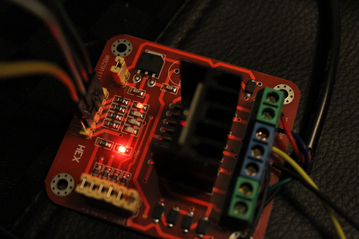
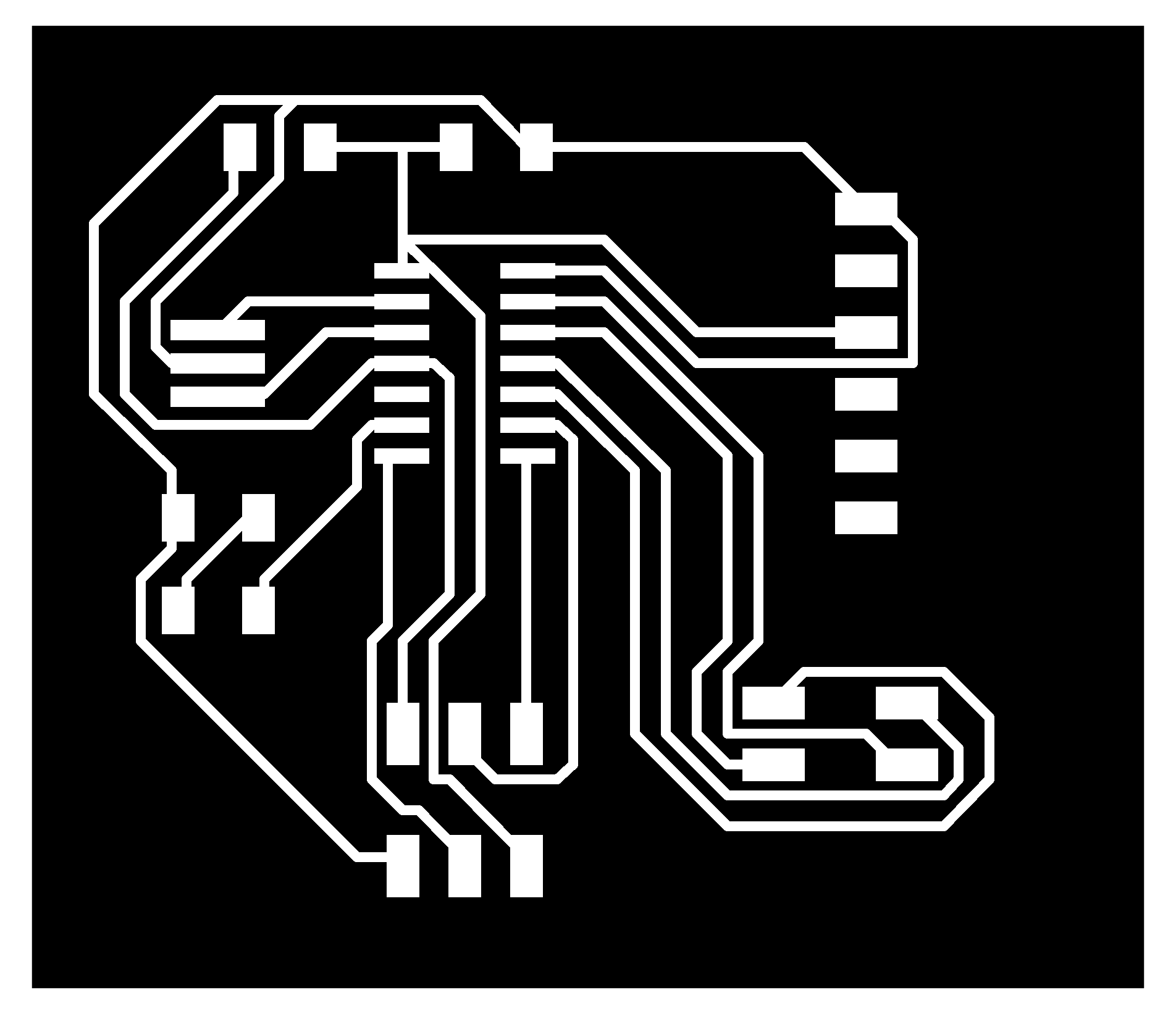
I will use for starting point the schematics that I designed during the Output Device assingment.
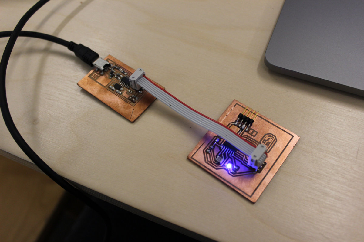
Since this board had a few issues, I decided to correct my mistakes and added a led, really useful to have a visual confirmation that the board is receiving data from the computer. I also reverse the orders of the header pins and oriented them in the same way as the FabISP pins: less margin of error (trust me on this). Small adjustment, big improvement in usability.
The making of the board and some odd behavior
I made the board so quickly that even Mathieu was surprised. As it was time to close the lab, I picked the components and went home. I soldered the board and even scavenged the header pins from previous failed boards.
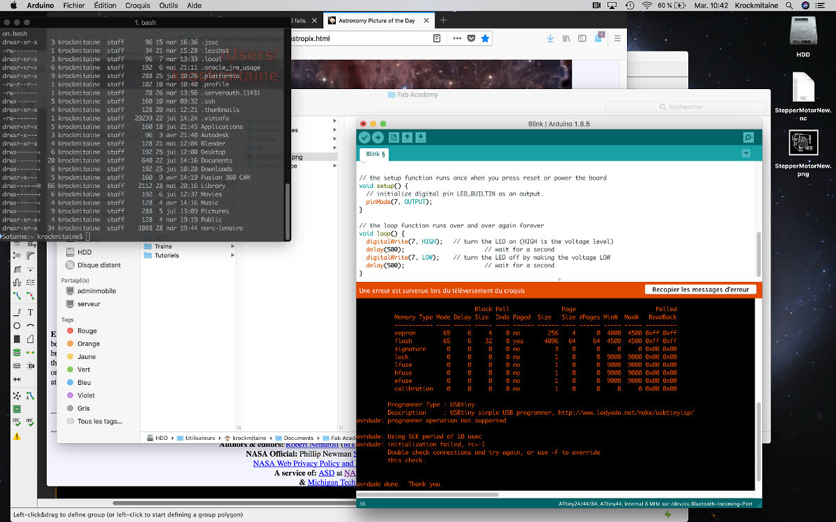
I put the board under power and I confirmed the connection of the FabISP under Material>USB for Mac. I configured the board for ATtiny44, 20MHz external clock and uploaded the Blink sketch and, to my surprinse and astonishment, the led blinked on order, but SLOOOOWLY. Still, an accomplishment. Having the memory of my previous struggle with the ATtiny in memory, I decided to burn the bootloader via the Arduino IDE to correct the timing of the fuse.
I then lost all contact to the board.
I really tried to get back the control of the board by switching the clock to internal 8MHz to no avail. I called it quit then. Distraugh. But I knew that the design of the board was functionning. The only plan that I had in mind was to redo the board.
But sleep can be a source of inspiration for new ideas. The previous day, for the first time, I used the hot air gun from the soldering station at échoFab and I was really surprised at how easy it was to remove a component with it. So, during the night, I came with the idea to remove the chip, replace it and forget burning the bootloader! No milling, almost no soldering and I'm back in business.
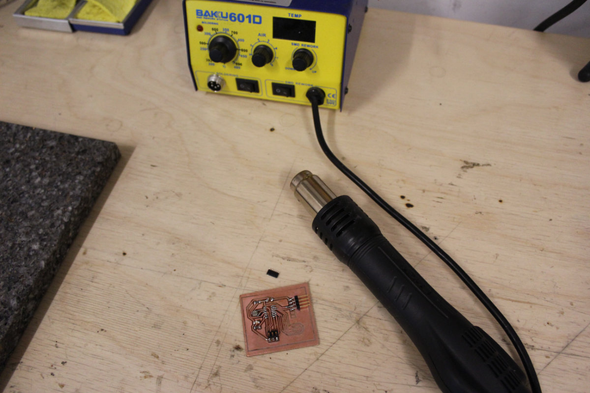
Everything went according to plan and around noon, the board was tested and the led was blinking.
When you assume things with electronics, it's an open door for problems
By now, I know that electronics design is painful. There's so many thing that you must learn all at once that you can loose your sight. In this case, I assume that my Output Device Assignment would save me some trouble. Only, I never re-checked the page, now it was the time, and saw trouble in the form of the driver motor. In the Output Device, I used a unipolar motor; in this one, I use a NEMA17 stepper motor, a bi-polar.
It's not the same.
The results...
Now was the time to plan a contingency plan: go through Montreal, a city (in)famous for it's orange cones to get L298N dual H-Bridge controller board from a brick and mortar place that sells such a thing, and more. Even this errand turns out to be a small adventure in itself, but I manage to get my hand on those drivers and get back to the lab.
I made the connections following a tutorial (that I lost when I shutted down the browser by accident) but got nothing working. Tried another one, still nothing. At last I followed this simple one that uses the Stepper Motor sketch included in the Exemples (Exemple>Stepper>Stepper_OneRevolution) folder in Arduino. I made followed the connections, added the ground cable to my board. On the software side of things, I simply hashed out the Serial.begin lines because I don't need the console messages and don't want to add a useless layer of complexity when using the SoftwareSerial.h library, thus simplifying the code. The sketch uploaded with no problem but nothing occurred.
At first I thought I got nothing, but then I noticed something has changed: from the four leds controlling the steps that were initially lighted, I now had three! Leaving the setup untouched led to a decrease down to two in some sort of blinking sequence. Maybe it's the input voltage of the card that's too low (5V), and the motor don't receive any power and stays cold. Tomorrow, I will try 12v like the GAM machine. BTW: I use 5 volts as precaution because I wasn't sure that the H-Bridge would reduce the power source down to 5 volts for the motor. Right now, I tend to make mistakes because it's the end of Fab Academy, about to leave for vacation, and I'm simply exhausted.
The next day when I came at the lab, I was sleep deprived and more inclined to leave it there then work on my problem. I started by making the necessary connections. Looking for a power converter took me a while. I made the necessary conversion for the transfer of the voltage to the motor. Since I found a multiple voltage converter, I measure the output voltage and modified it appropriately for 12 volts. This wouldn't make a difference at all, the board would filter down the voltage appropriately, but knowing the input voltage is insurance if something goes wrong and someone ask me "What's the voltage?"
Finding my way to success with a problem, a correction, an unexpected solution and an almost catastrophe
So, everything are in place with the boards (FabISP and Stepper Motor), the L298N motor driver and the stepper motor. I power everything and like yesterday's evening, the lights are feeble and there's no mouvements.
I asked around and nobody's has experienced such a problem. François sitted with me and we started to browse the Internet, looking at the datasheet of the L298N. Learned a lot reading this documentation but came empty handed. Just before we left for lunch, I took a glance at the sketch and though I was tired, it hit me: I forgot to change the pins from the default Arduino Stepper motor exercice to my setup! So I changed the line Stepper myStepper(stepsPerRevolution, 8, 9, 10, 11); to Stepper myStepper(stepsPerRevolution, 3, 2, 1, 0);. Immediately, the feeble led became bright and working in sequence. But the motor was still cold.
Went back doing more research. By then I was alone, François hanging around, preparing to leave. As we were discussing, he suggested to change my approach and try with an arduino. Good idea. So I switched the board and made another setup. I powered the board and surprise! The L298n leds were blinking in seqence but the motor was still cold. What's more, the serial console was sending me messages (clockwise-anticlockwise).
So, it was obvious to me that the sketch was ok, the setup was ok and in the same token, my board was ok. The location of the problem was the L298n driver board. I made the appropriated search on YouTube and found this one with the same model. I followed the author along, noticing the warning that if you don't do this, the motors won't work. I found that I had to feed two pins (ENA and ENB) with 5 volts beside the IN1-IN4 pins. I made a jumper wire and connected this makeshift connection to those pins and sure enough; the motor was making noise and was working! I finally founded it!.
Now, I needed to transfer from the Arduino to my board. And I had to find another 5 volts to feed the pins. I realised that my FabISP feed 5 volts to the StepperMotor Board. That said board had a FTDI pins that has a... 5 volts! So I need to transfer the jumper wire to the FTDI pins and I'm ok. But I need to repair the FTDI pins because I manage, somehow, to cut the trace at the 5 volts positive pin. I needed to make a jumper and it will be done.
Remember when I said I was tired in the morning? This was no longer the case. I quickly made a jumper out of a resistor who gladly gave me some of it's wire for a good cause. I soldered the pin and it was ok, cut the excess wire and made the appropriate connections and put the voltage on and WHAAAT? SMOKE!!!! I didn't think twice and pulled the connector and left the board to cool down. I looked at them, the ribbon cable was not in reverse and all looks fine. I took a good look and I found the reason: when I made the jumper, some solder made a bridge to the negative trace that passed right beside the 5 volts pin!
I desoldered the connection and soldered it again take good care that there was no bridge.
As for the boards, the FabISP and the StepperMotor, I assume that I react quickly enough that the boards were still functionning. And having left them alone to cool down probably helped. That accident previously happened to me and the board had survived. So when I reconnect everything I was confident that it would be ok AND IT WAS!
And the stepper motor was running!
The making of the base
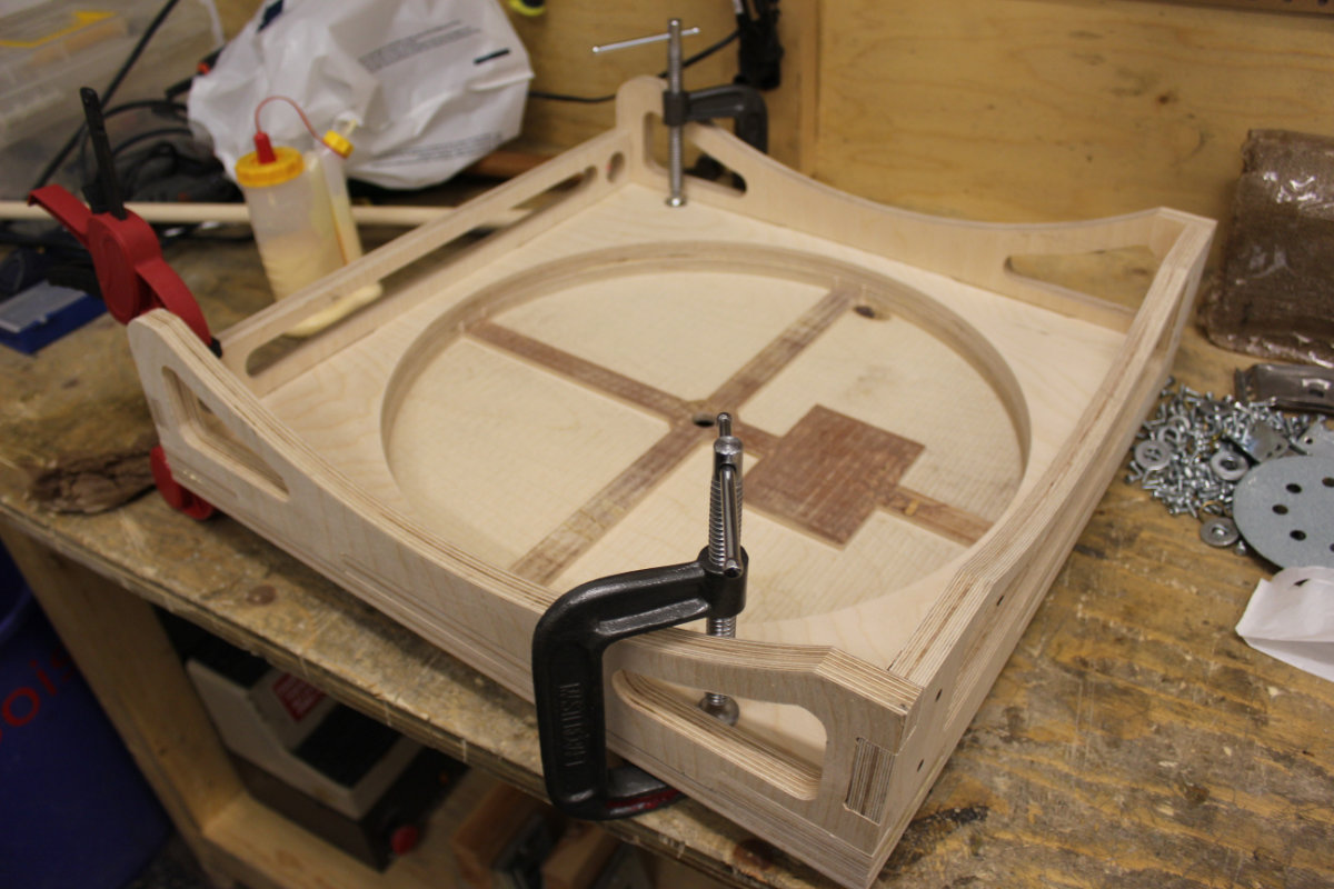
This morning at the lab, it dawn on me that I was actually doing the final assignment. What I made yesterday was the toughest part: the motorising of the motor with my board. Now was the time to make the mechanical gears and make the support for the motor. Initially, I had the idea of making a 3D base for the motor but I settled for a more primitive way of doing things: making shims with the laser cutter and gluing the parts to the appropriate height for the motor and gear.
So, the marching order were to first built a simple base, screw the lasy susan on it, glue the rocker base, put the rocker base on top of the lasy susan and put a dowel for the center pivot. After this first step, verify that everything is functionning, Then add the gear train and electrononics.
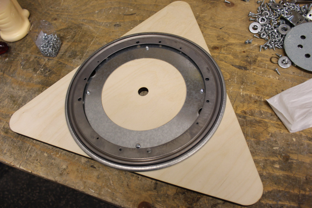
It was now the time to glue the upper part of the rocker baee to the lower base. While the glue settled, I laser cutted the base with two thickness of ¼" plywood. I glued these two parts together. As an aside, I configured the top base with an outline of the same inner diameter of the lazy susan so I will be able to center the two parts together. I then screw the lasy susan to the base then the lower panel of the rocker base. I finished with adding the center dowel with a dab of glue. I then made a rotation test and it went with flying colors.
That test went with flying color. It was now time to put the electronics on the top of the base, put the gear train and finish it off.
I went to the computer and headed to Geargenerator.com to configure a gear train, downloaded it and uploaded the file in Inkscape. It's really fascinating how fast that machine can make a gear. So, I had my gears, my motor, my shims and it was time to assemble it all.
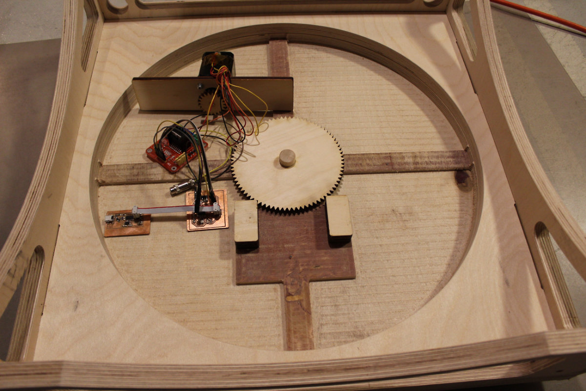
Afterward, I screw together the components to the base and added some plastic tubing to protect the wires. I made a clean setup and redone the connections for a final test.
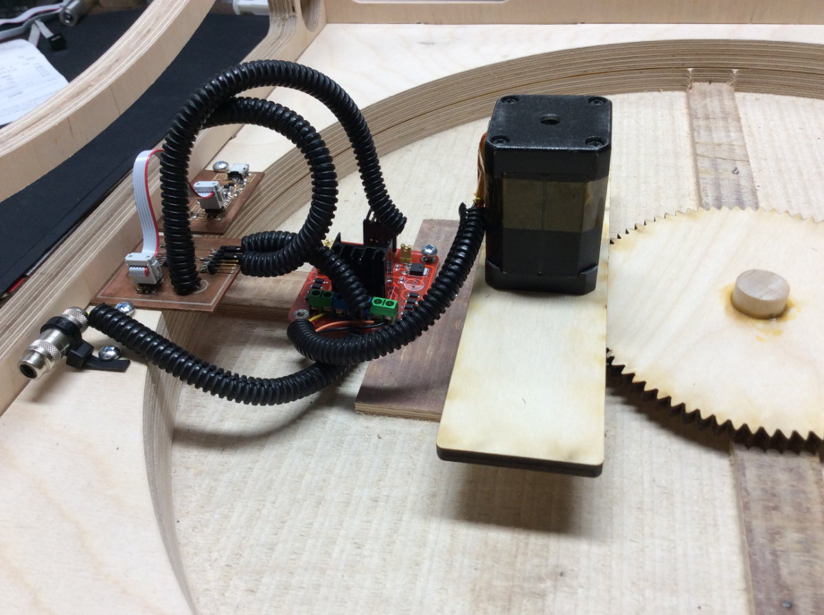
Then I made one last run with the base to see that everything is in working order.
Bill of Material
The Bill of Material (BOM) for this first phase is the following:
| Num. | Qty. | Description | Vendor | Price |
|---|---|---|---|---|
| 1 | 1 | 19mm Baltic Birch Plywood Sheet | Langevin Forest | $68.85 |
| 2 | 1 | NEMA19 Stepper Motor | Unknown maker. Found at échoFab inventory | Free |
| 3 | 1 | MOT-L298-1 DC Dual H-Bridge Motor Controller Driver Board | Abra electronics | $9.94 |
| 4 | 1 | ATtiny44A-SSURCT-ND | Digikey.ca | $1.18 |
| 5 | 1 | 10K Ohms SMD resistor | Digikey.ca | $0.27 |
| 6 | 1 | 220 Ohms SMD resistor | Digikey.ca | $0.15 |
| 7 | 1 | LED SMD | Digikey.ca | $0.25 |
| 8 | 1 | 1µ SMD capacitor | Digikey.ca | $0.11 |
| 9 | 2 | Amphenol FCI 95278-801A08LF | Digikey.ca | $0.76 |
| 10 | 1 | Prototype Board Unperforated | Digikey.ca | $20.94 |
| 11 | 1 | RCA jack for power supply connection | Unknown maker. Found at échoFab inventory | Free |
| 12 | 1 | FabISP | Made by myself during Week5, Electronic Production | Free |
| 13 | 1 | Multi Voltage power supply | Unknown maker. Found at échoFab inventory | Free |
| 14 | 1 | USB to mini usb cable for connecting the base to the computer | Unknown maker. Found at échoFab inventory | Free |
| 15 | 1 | Electrical wires | Unknown maker. Found at échoFab inventory | Free |
| 16 | 1 | ¼" ID x 10' plastic loom | Mastervox electronics | $4.99 |
Final thoughts
I'm really happy that my prototype is working, and the way that my concepts went according to plan, but there's still plenty work to do. The areas that need some attention for the next iteration are the following:git
- I need to understant those chips. AVR Programming: Learning to Write Software for Hardware is a must read.
- I need to find my way on how to properly set the fuse of the ATtiny44.
- I'm not satisfisfied with the gear train that I designed. The motor is in the way with the lower optical assembly. Next time I will use a worm gear train, my initial idea.
- I will need stronger motors to drive the complete assembly.
- I need to change the base. As it is, it's nice but I want the base with two handles for ease of transport. Also, I will change the side bearings with appropriate support directly under the teflon bearings. Ideas to explore on the MKII version
Bibliography
Adding to these initial titles are the following webpages that will guide me through the though process to complete the project.
- A telescope project made during the 2017 FabAcademy
- Tanvir, Nasser, Zenith Scope, http://archive.fabacademy.org/2017/fablabkochi/students/314/project.html
- Designing the gears :
- Otvinta, Tutorial 2: How to Model Globoid Worm Drive in Blender, http://www.otvinta.com/tutorial02.html
-
- A GoTo control using arduino. This project is for an equatorial mount, we have to convert the program to an Altitude-Azimut mount.
- Winter, Otto, GoTo Telescope Control for rDUINOScope, https://hackaday.io/project/21397-goto-telescope-control-for-rduinoscope
- A GoTo control using arduino. This project is for an equatorial mount, we have to convert the program to an Altitude-Azimut mount.
-
- A web page describing how to convert celestial coordinates
- Burnett, Keith, Converting DA and DEC to ALT and AZ, http://www.stargazing.net/kepler/altaz.html
- A web page describing how to convert celestial coordinates
-
- A GitHub project with a RA/DEC to ALT/AZ program
- Hofman, Mats RA Dec to Alt Az converter, https://gist.github.com/matshofman
- A GitHub project with a RA/DEC to ALT/AZ program
-
- Another conversion program:
- Wilcox, Christopher Conversion from Right Ascension/Declination to Altitude/Azimuth in Matlab, https://www.mathworks.com/matlabcentral/fileexchange/27071-conversion-from-right-ascension-declination-to-altitude-azimuth-in-matlab?focused=5150032&tab=function&requestedDomain=true
- Another conversion program:
-
- Another influential project. In two parts
- Hauck, John Michael, Motorizing a Telescope, part one, http://w8isms.blogspot.ca/2013/09/motorizing-telescope-part-1.html
- Hauck, John Michael, Motorizing a Telescope, part two, http://w8isms.blogspot.ca/2014/11/motorizing-telescope-part-2.html
- Another influential project. In two parts
