The Tracking System
Building the electronics
Before tackling the most challenging part, the electronics, I must understand what's really going on with the AVR programmer. I succesfully programmed ATTiny's by sheer determination and hard work but I must confess that I was uneasy about the process. So now's the time to step back and understand the process.
A Case for Building a Trusted Workflow
During Fab Academy, I learned electronics the hard way. I started out from basic knowledge to designing and building boards in a week. I was faced with too many unknowns, and when problems came up, and they came up quite rapidly, it was really difficult to locate the problem: is it the schematic, the board, the electronic or the soldering? Making the jump from schematic to Surface Mount Soldering was quite a big step and I felt uneasy about the workflow. While agreeing that making electronic boards are now quite cheap, following this workflow is costly in time. Still, I totally agree that doing breadboard prototyping has it's own subset of problems: bad quality of said board and components, bad connections with the jumper wires, all this can make your prefect desing generating headaches because one single component is not functionnal.
During my studies, I came about that book, AVR Programming: Learning to Write Software for Hardware by Elliot Williams. Althout the description was very interesting, I didn't had access to this book. Plus I had to learn C! As the workload was already important, I had to let it go, promising myself to come back at a later time. Eventually, I bought the e-book adn started to read. I also bought the USBtinyISP AVR Programmer kit from Adafruit. At the time, I wasn't too sure about the reliance of my own programmer and bought it just in case. I soldered the kit but never used it (true!) because I finally manage to make an ISP programmer. This kit is well made and the instructions are nicely done.
With these tools in hand, I was ready to jump. I started to read from page one and ordered the basic components for the first chapter. The author is guiding the student one step at a time for the first experiment, how to make the first setup to verify that everything goes according to plan.
As I was preparing the USBtinyISP, I checked the output voltage directly with my multimeter. It was too low and I realised that I need to put the jumper that I put "somewhere". I found the jumper in question, put it back at it's place and now had a nice 5 volts reading on my multimeter.
Testing the hardware
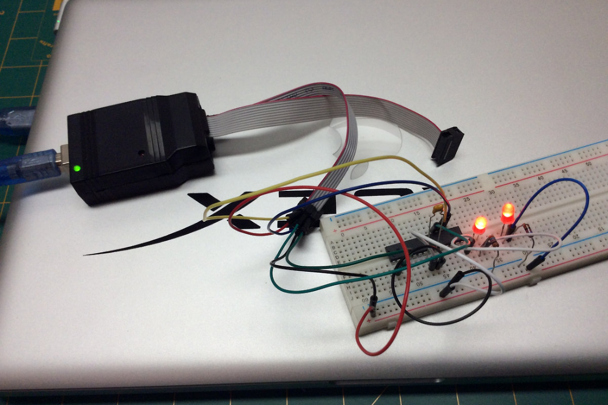
I prepped the board for testing the connection, a simple led to be lighted by the 5V from the ISP. This simple test failed. I was puzzled. I knew my voltage was correct, so it was the hardware. At first I thought that I had a brown out led, but changing the led for another didn't change the results. Then I thought, why not test the setup by manually making the connection? It wasn't easy, but I manage to connect the led and the resistor to the 5 volts pins and voilà, the led finally powered. So it was the board. I then noticed that the symbols for the + and - rails on my board were cut in the middle compared to the one on the book: my board need jumpers if I want to use the full extent of the connectors. Once I made this discovery, I made the setup on the first half of my board and the connection was made. Once this step was done, I completed the setup with an ATMEGA128, a capacitor, a led and resistor. The hardware side was now complete.
Testing the software
For my HTML coding environment, I'm already using Atom, it's full of nice packages and you can configure it to your personnal taste. I added the PlatformIO package for coding the ATMEGA. I uploaded the code from the author's Github repository and stated testing. Under PlatformIO, there was the option of a terminal. I started to testing the connection between avrdude and the chip and got, to my surprise, a positive answer. I loaded the C code and typed "make flash" and to my surprise (again) I got a nice blinking led telling me that everything is actually working. Following on this success, I messed with the code and noticed the error messages as a learning experience.
What did I learn?
A lot actually. Now I'm talking directly to the chip, I'm learning C, I'm working in a new environment made for the IoT. In hindsight, the experience that I learned during Fab Academy was extremely useful: how to read schematics, connecting the isp pins (miso, mosi, sck...) and problem solving (it took me less than an hour to get everything working). I gained a lot in assurance and I'm ready for more.