Input Devices
Week 11

This week's assignement is to design a circuit board with a microcontroller, add a sensor and read the output. As I'm learning how to read and interpret correctly a spec sheet, I will design a simple board with a button, add a LED and a crystal resonator just to be on the safe side. As Neil said, I can add a crystral to my chosen board as he has left it just to keep the board simple.
Eagle
I fired up Eagle and added the parts to my schematic. I first made it without a crystal but I listening the lesson, I noticed that by adding it, I will gain more precision in the reading of the pins at the end.
To gain time, I used was I've done yesterday as a starting point but I change the ATtiny44 to ATtiny45. I added the FTDI input, the 2x3 header, a button, a LED and a 49.9 ohm resistor so that I have a visual cue when I press the button and last a 1µF capacitor. I added all the lines and named them appropriately.
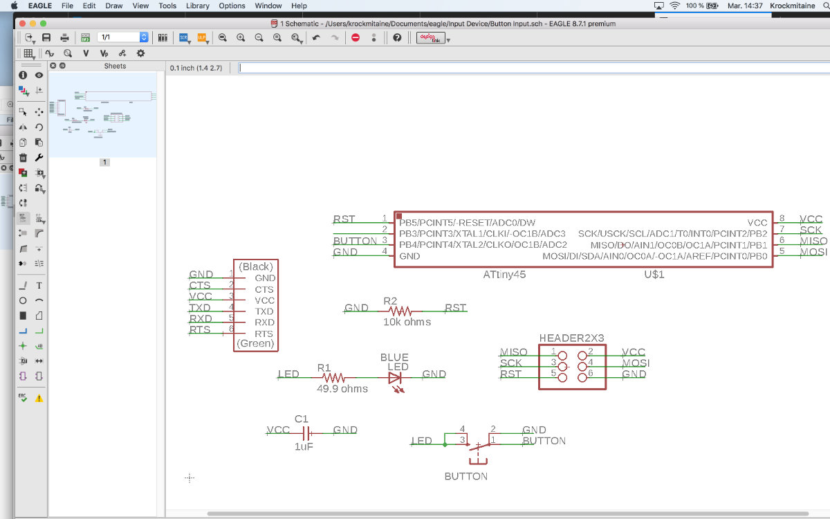
I then started to read the documentation of the ATtiny, looking carefully at the output pins in Chapter 10
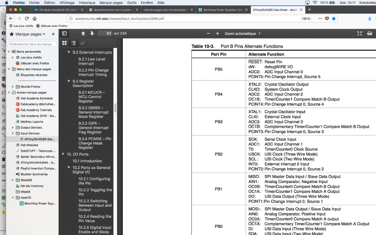
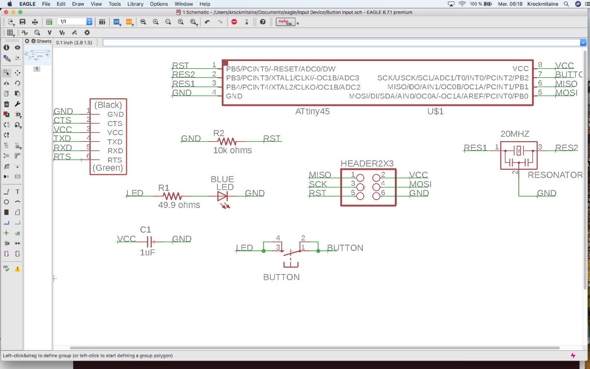
It was then that I realised that adding a resonator don't involve much work and if I'm correct, adding a crystal will add precision to my reading. It would also mean that I'm gaining expertise at reading the doc. So I added a crystal and connected the pin3 (Port B, Bit 4 or PB4) to one pin of the crystal. I then followed by adding pin2 (Port B, Bit 3 or PB3) to the opposite side of the crystal. I finished by adding the ground to the third pin of the crystal.
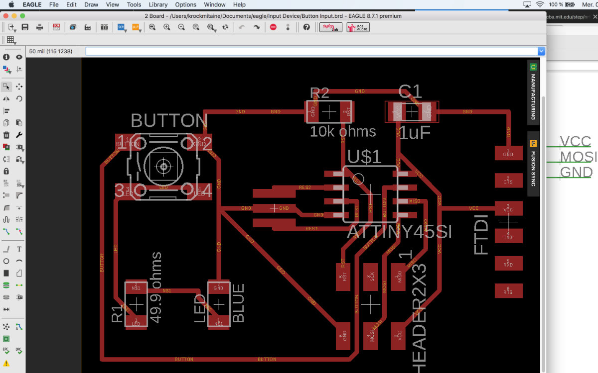
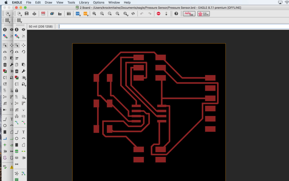
All is set and seemed to be good. I then switch to board view and placed my components on the board, configured DRC with 16 mil traces and size. My first suggestion wasn't to my taste and took another one.
I noticed that there was a problem with adding the button: adding a crystal takes all the pins and I can't no longer use the pin3 so I have to figure out how to complete my schematic. Further reading made me realise that I can use the pin 7 (Port B, Bit 2) instead.
So now the schematic is complete. Let's see if my assumptions are correct.
The Mentor
There's a reason why you have a mentor: he's there to guide and inspire you.
When you realise something...
I showed my project to my mentor and, althought right about the schematic, he made me realise that my project is, well, bland. I must confess that I wasn't too much inspired as I'm really looking for the Output devices assignement. He suggested to me why not make a DIY pressure sensor. It's simple to make and fun to realise. I found an Instructable with the arduino code to test the sensor. So incredibly simple and fun to make so I was sold.
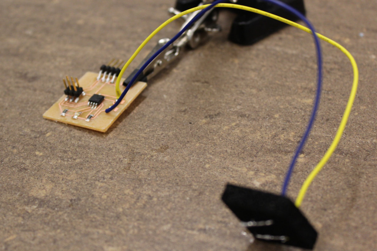
How to make a pressure sensor in three easy steps.
This is what you need to make a pressure sensor.
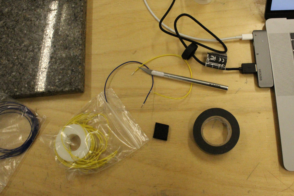
The first step is to solder the tips of the two wires so that you don't have small filaments going haywire. You then slice two slits in the foam and then pass the wires throught the foam. You bend the wire 90° and place them in parallel, flush against the surface of the pad.

You put some electrical tape around the foam and wires and you're done. Sorry, I lied for the third step, it doesn't exist.
Testing the rig
I used a third hand to hold the wires with the tips of an multimeter and locate the appropriate scale for the resistance to show up. In my case, I was reading 10K ohms with no pressure. For those who wonders, tha stickers comes from the Daughter during her sticker phase and wanted to spice up my tool.
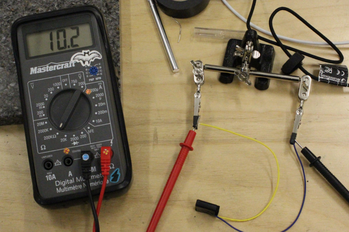
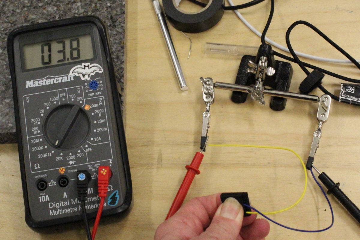
Now the sensor is complete. Let's make the breadboard and connection with an Arduino and see if this sensor can do something.
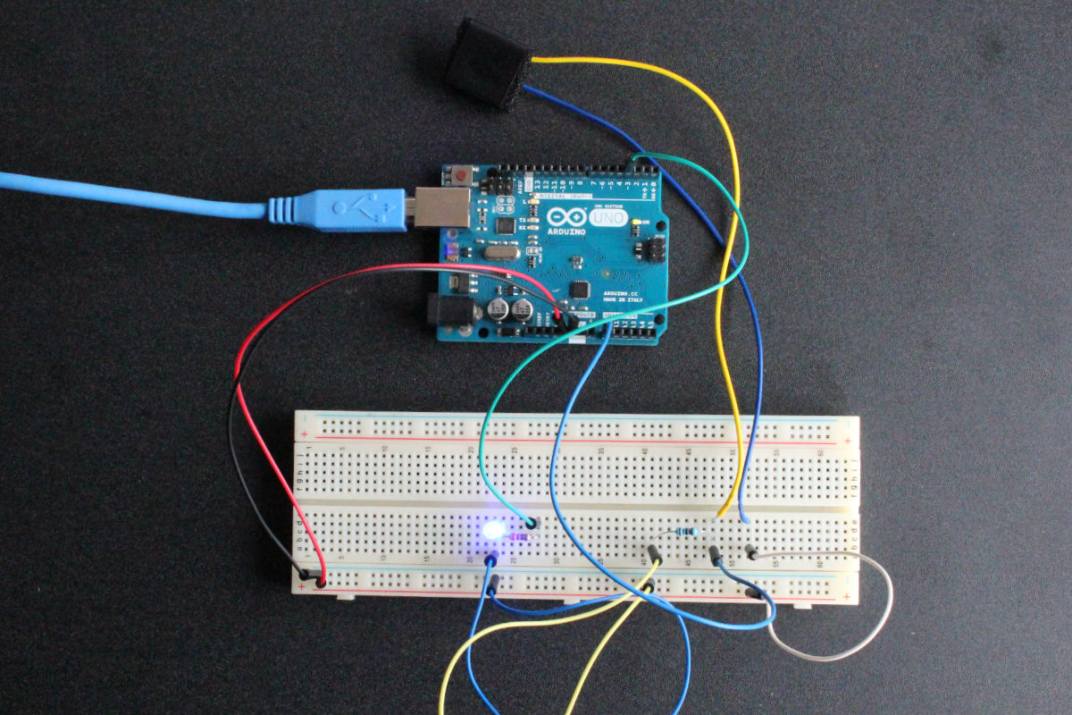
Part Deux: The Breadboard and Arduino setup
Now is the second part of this setup to built. We will built a setup with an Arduino and test it. Once done, we create a schematic of it in Eagle with a ATtiny45 and create the board.
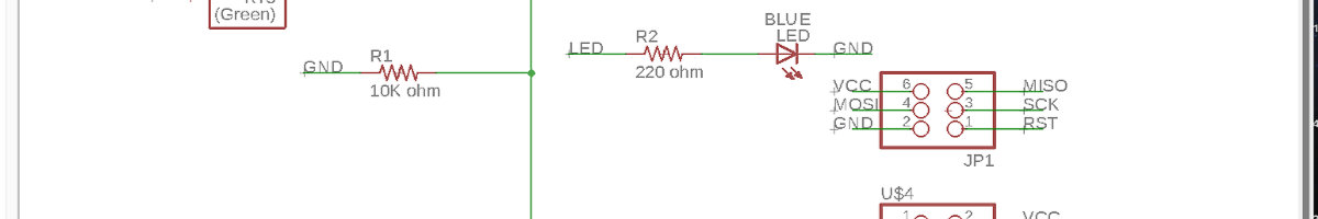
For this step, we will need one resistor of 10K Ohms and another one of 220 Ohms, a LED, a breadboard and an Arduino board. We make the circuit following this schematic:
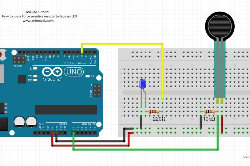
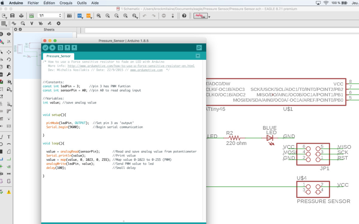
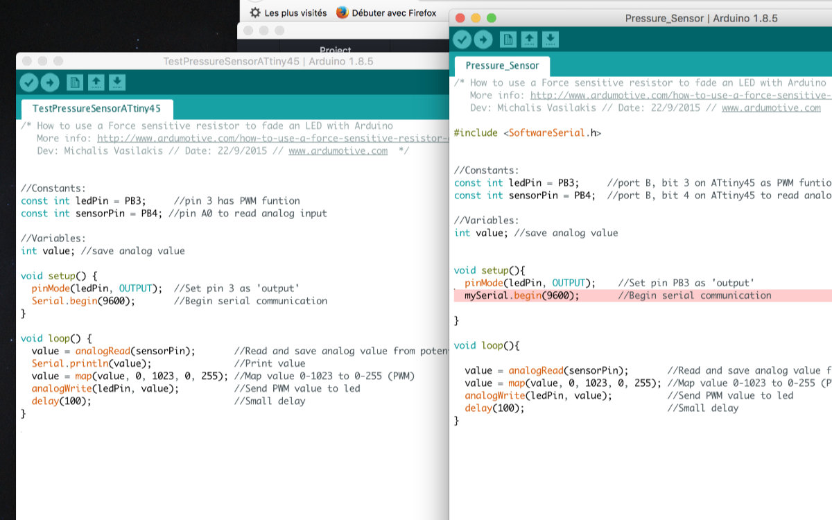
We load the following sketch:
/* How to use a Force sensitive resistor to fade an LED with Arduino
   More info: http://www.ardumotive.com/how-to-use-a-force-sensitive-resistor-en.html
   Dev: Michalis Vasilakis // Date: 22/9/2015 // www.ardumotive.com  */

//Constants:
const int ledPin = 3;     //pin 3 has PWM funtion
const int sensorPin = A0; //pin A0 to read analog input

//Variables:
int value; //save analog value

void setup(){

  pinMode(ledPin, OUTPUT);  //Set pin 3 as 'output'
  Serial.begin(9600);       //Begin serial communication

}

void loop(){

  value = analogRead(sensorPin);       //Read and save analog value from potentiometer
  Serial.println(value);               //Print value
  value = map(value, 0, 1023, 0, 255); //Map value 0-1023 to 0-255 (PWM)
  analogWrite(ledPin, value);          //Send PWM value to led
  delay(100);                          //Small delay

}
If all goes well we have a lighted LED that goes brighter when we press the pressure sensor because there is less resistance to the electrical current.
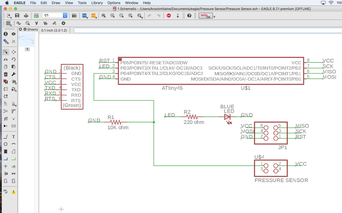
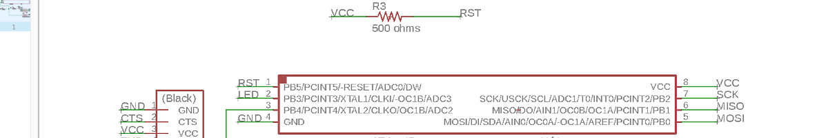
Once we have the confirmation that this schematic for the Arduino board meet our expectations, we must convert this to an Eagle schematic and make a circuit board using an ATtiny45. As I looked upon the ATtiny chip, it's obvious that there's a lot less pins that are available as inputs than the Arduino board: I must adapt the Arduino sketch to this chip. To help me along, I will use the ATtiny Pinout schematic. This schematic defines the pins used in an Arduino and the equivalent on the ATtiny.
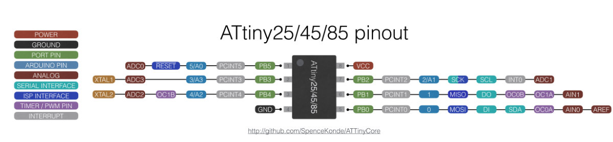
We first start with defining what is used by default on the chip in Eagle. As we have 8 pins, there's 6 pins already in use (VCC, SCK, MOSI, MISO, GND and RST). There's two pins left. Of these, one pin drives the LED (pin2). There's only one input for our pressure sensor: pin 3 (or Port B, bit 4). If we look into our schematic, we see that this pin is the equivalent of pin A2 on the Arduino board. So we must modify our program accordingly.
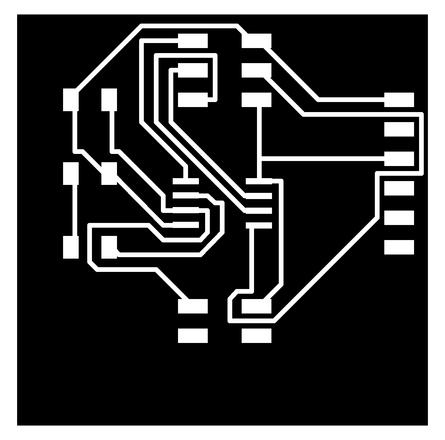
I export the file in monochrome, in black and white at 500 dpi. I crop the png file in an image editor and then upload in Fab Modules. In Fab Module, I increase the dpi to 1000 (because of a bug between Eagle and OS X), choose G-codes (.nc), PCB traces as the process. I then increase the cut speed to 6 mm/s, change the cut depth to 0.08mm and press calculate.
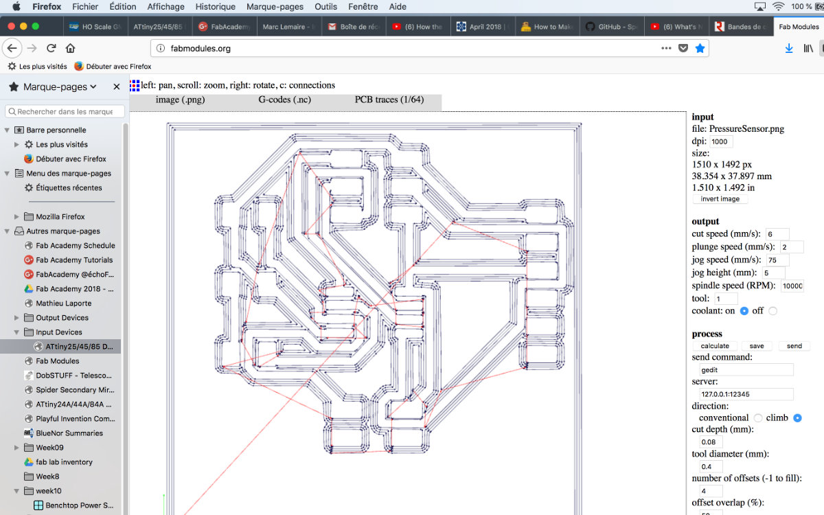
I then save the file in preparation for the milling of the board.
The Milling
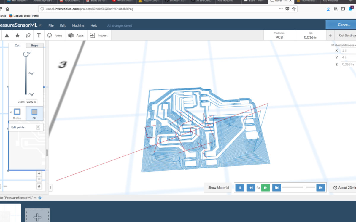
The milling was done with the Carvey available at Alec's lab. Since this is a new environment to me, I took me some time before I got everything right. The Easel interface is easy to master, but it has it's quirks. First I had to transform my png file to svg using Inkscape. I had an issue with the exported svg file as Easel kept telling me that my file contained objects that are not supported by Easel. I tried to fix the issue with Inkscape and Affinity Designer but I kept having this issue. Try as I might, I kept receiving this message even though I saved the file with plain svg. Eventually, Alec converted my png file with Illustratrator and we moved on.
Once uploaded, I had to change the measuring unit for imperial, change the material to PCB and add the dimensions of the mill (1/32").
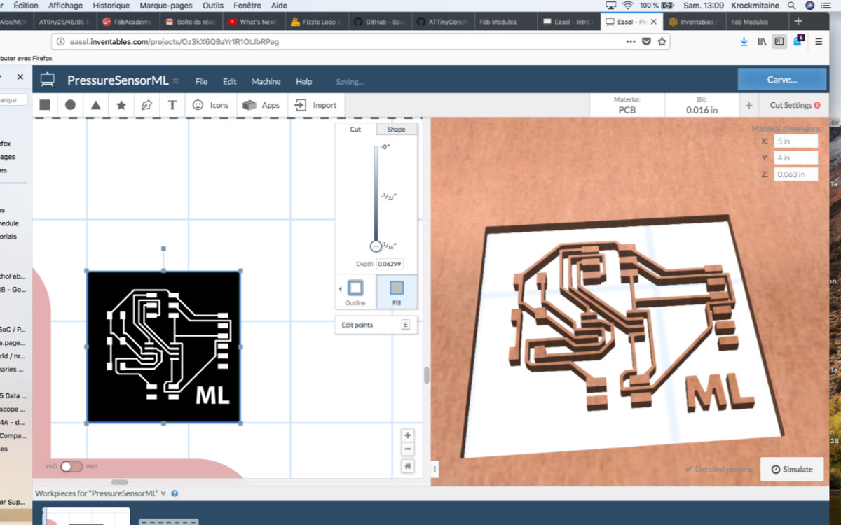
Once done, I had to select the background and define the dept of the cut: I followed Alec's recommendation and choose .002" depth.
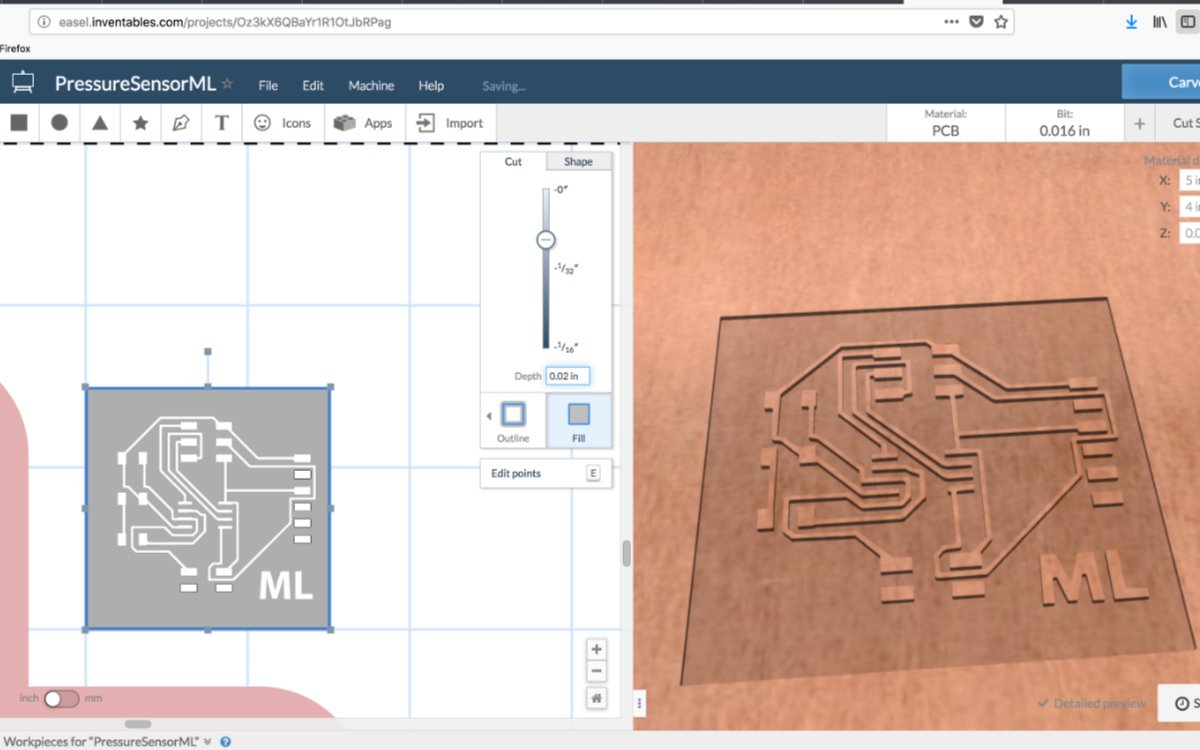
And I started the simulation just to make sure. Then I press Carve, confirms the next steps and the Carvey started to get to work.

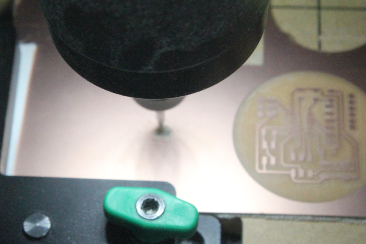
I must add that the end results are beautiful and perfect in every sense.
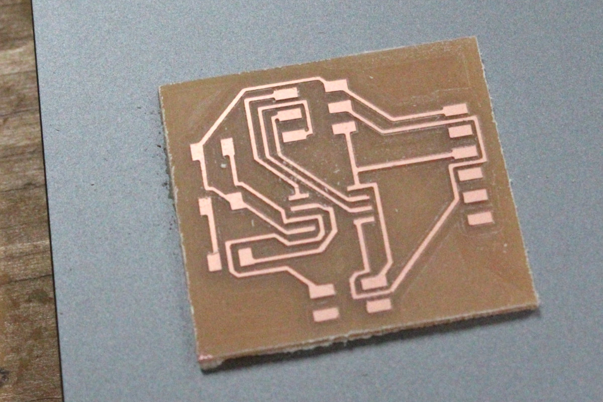
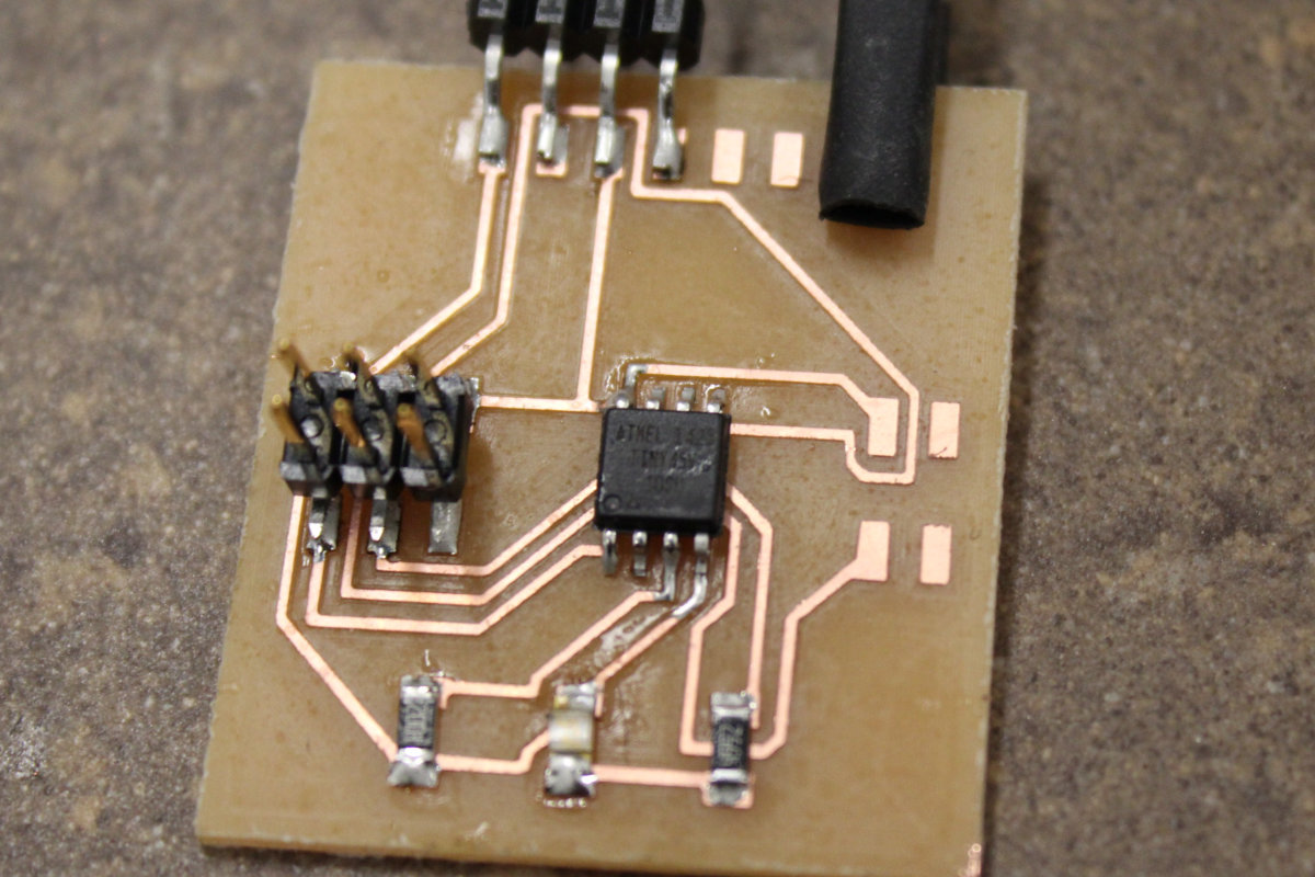
The board is now ready to receive it's components. As I don't have the parts, I must wait until my next visit to the lab to solder the components. At that stage, I am more confindent with my soldering skills and this step went without any problem.
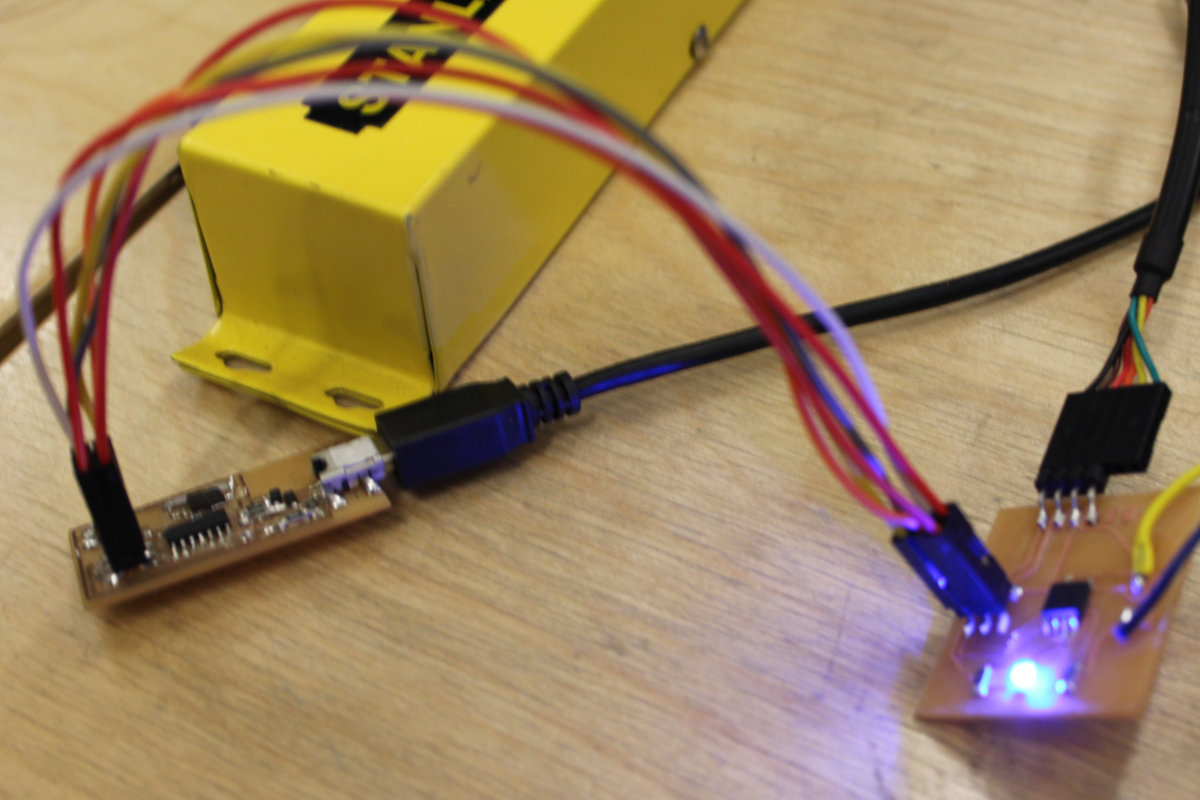
Programming the board
The smoke test went without any problem, the (feeble) lighted led was the telltale indicator that the board was functionning. The led isn't bright because I wanted to proceed and picked up a 499k ohm instead, since there wasn't any 220k ohm resistor in stock.
Some odd behavior
As I was looking for tape to complete the sensor, I picked up some red colored electrical tape. Since I made a completely new sensor from the same components, I assume that the sensor had the same behavior. Not so! As I later tested my unit, it seemed that the red tape made the pressure sensor less sensitive than my first iteration: the reading stays almost the same whether or not I pressed the sensor. I change the tape to regular, and fresh, black electrical tape and the sensor is functionning as I get different readings when I press and release the sensor.
The programming of the sensor
Now we get to the most interesting part: the programming of the ATtiny45 as a pressure sensor. I connected the FabISP to the Pressure Sensor, started the Arduino IDE and load the sketch that I just use. I change the sketch constant for the appropriate pins of the ATtiny45, PB3 and PB4 for the LEDpin and sensorPin and verified if everythiong was ok. To my surprise, I had a problem with the Serial.print(value) with the message that 'Serial' was not declared in this scope. I googled the message and came up with the solution that I need to add a library by adding the line
#include <SoftwareSerial.h>Further investigation led me to read forums threads, and came up with a more understanding of what I was actually doing. My first stop was to search through the Fab Academy archives and found this project. This one uses the TX and RX inputs of the FTDI input, and a ATtiny44 instead of the ATtiny45 that I use. Interesting solution but in my case would leave me with one pin available. Plus the downside of having to redo the sketch, the board and the soldering, which I didn't like at all. Wanting to avoid going back to square one, I opened up my original sketch, powered my board and check everything. Everything was fine. I'm even having a nice output on the serial terminal that varies as I press the sensor. So, on the hardware and software side of things I'm fine: it's the translation of the sketch from the Arduino to the ATtiny that I have a problem.
I found this tutorial on High-Low tech.org, which seems to be the entry point where everyone goes to when doing what I was doing. It's a stepping stone but still not an answer to my problem. I pushed on, and find this interesting thread that somewhat relates to my problem. Whithin the replies there's someone who says that I must add the SoftwareSerial library, which I've done. Also, another one who says that the issue is: This answer is incorrect. The actual issue appears to arise from mixing up the ISP sketch for the ATmega with the blink sketch for the ATtiny. – Chris. Humm, this well may be the case. Also: Throw some dummy code at the very top of your sketch (yes, even before includes). Mine: char foo;
So the solutions seems to be
- 1- Verify the setup for programming the board;
- 2- Add the #include line at the top of the file;
- 3- Add dummy code.
So, my nightmare may have begun when I unknowingly added two letters to the Serial declaration! I removed the guilty parties, from mySerial.begin to Serial.begin, and the sketch compile fine wether or not the SoftwareSerial is included.
Fingers crossed that this is the solution and tomorrow this will be done. Oh! And I need to find a lower value for that resistance, that led is really too faint.
The debugging of said sensor
So I went to the lab with a more or less good feeling that I workded hard and that I was more or less on the good part of fixing my problem. Not so with ATtiny. This small chip is a VERY tough nut to crack. As noted, since there is no hardware serial port we need to create one with the SoftwareSerial library. I worked really hard to debunk the microprocessor by myself but in the end, I had to call the help of Mathieu, who then called in Craig to help not only me but also George, who was also stuck with a very similar problem.
But first, I had to replace that resistor that was too high with one more appropriate for the task at hand. That first job went easy and fast, I replaced the component with one 49.9 ohms resistor. The bright blue light that came out of it once the power was on told me that this one was fixed.
Another unexpected problem came when I tried to connect the two boards with a jumper cable. It came with an connection error. I checked the cable and came rapidly to the conclusion that the cable was not correct; the connections pin holes didn't correspond to their respective number/places at both extremities. I quickly made another one. The visual and physical inspection were good but I learn something new: be careful when you design something on Eagle because the 2x3 header was upside down! I couldn't connect with the cable! Unless I redo the whole shebang, I couldn't use the cable. So I went with good old fashion jumper cables for the connection. Once this was done I had a complete setup ready to be programmed.
After that the next problem to fix was to program the board, and there I hit a wall: trying to program the ATtiny chip. I could compile the code and upload it but couldn't have the serial input showing on the serial terminal.
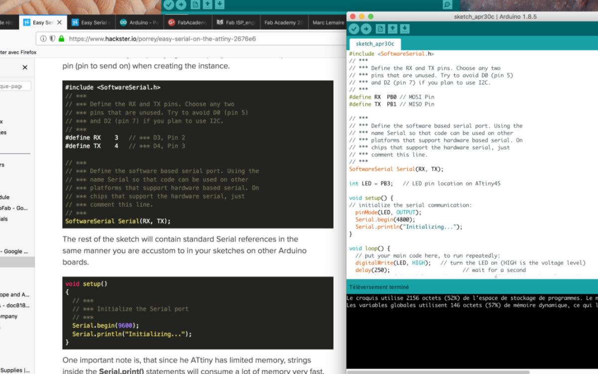
After trying many different options that revealed themselves to be dead ends, Mathieu pointed me to a tutorial on Hackster.io titled Easy Serial on the ATtiny. I thought that I've covered all my bases with documentation by that time but it seems not. The author noted :
The Atmel tinyAVR MCU's are great little chips for projects but can prove difficult to debug. Some ATtiny chips do not have direct support for hardware based serial and therefore the Serial object is unavailable in your code [...]
So true...
' I worked at a feverish pace, trying to get something out of the serial terminal but to no avail. The chip could't understand the command that I was uploading. The main problem was how to define TX and RX so that the SoftwareSerial library would be working correctly.
We finally had a remote meeting with my regional supervisor, who lives on the other side of the world in New Zealand. We share code on codeshare.io and debunk one problem at a time. We connected the two boards but we didn't go anywhere. We then conected an Arduino board to my Pressure Sensor board and started looking for solution in the sketch file.
First, after the definitions of the pins TX and RX for SoftwareSerial, instead of having SoftwareSerial Serial(RX, TX) we change it for something less confusing for the ATtiny: SoftwareSerial tinySerial(RX, TX);. And we added the line tinySerial.println("Lights...") at the end of void loop(); declaration and it compiled and load just fine!
Said code in question. Remember that for your application YMMV. If it doesn't work, change the TX, RX pins.
//Good afternoon Echofab

//pinouts for attiny45 https://camo.githubusercontent.com/081b569122da2244ff7de8bae15eb56947d05cc8/687474703a2f2f6472617a7a792e636f6d2f652f696d672f50696e6f7574543835612e6a7067
//pinouts for attiny44 https://camo.githubusercontent.com/d46f3f004aaf977040d933ae5eaf25d22d33eac1/687474703a2f2f6472617a7a792e636f6d2f652f696d672f50696e6f7574543834612e6a7067

// Uno ----- Your board
// 5v ->     Vcc
//Gnd ->     GND
//TX(1) ->      MISO
//RX(0)  ->     MOSI

#include
// ***
// *** Define the RX and TX pins. Choose any two
// *** pins that are unused. Try to avoid D0 (pin 5)
// *** and D2 (pin 7) if you plan to use I2C.
// ***
#define RX  1 // MISO Pin
#define TX  0 // MOSI Pin

// ***
// *** Define the software based serial port. Using the
// *** name Serial so that code can be used on other
// *** platforms that support hardware based serial. On
// *** chips that support the hardware serial, just
// *** comment this line.
// ***
SoftwareSerial tinySerial(RX, TX);  // RX, TX

int LED = PB3;   // LED pin location on ATtiny45

void setup() {
// initialize the serial communication:
  pinMode(LED, OUTPUT);
  tinySerial.begin(9600);
  tinySerial.println("Initializing...");
}

void loop() {
  // put your main code here, to run repeatedly:
  digitalWrite(LED, HIGH);   // turn the LED on (HIGH is the voltage level)
  delay(250);                       // wait for a second
  digitalWrite(LED, LOW);    // turn the LED off by making the voltage LOW
  delay(100);
  tinySerial.println("Lights...");
}
Small victory, at last!
But it was short-lived
Mishap
While I had a working board, it was the end of the day and I had to leave the lab. The next day, I tried to reproduce the connection but to no avail and had to leave it there.
Later on, while verifying the connection, I force the FTDI plug a little too hard and this completely rip off the FTDI connector from the board and ripped one trace of copper. The board was done and nothing else could save it. By chance, it's not a complex one and it was easy to redo, especially that I'm efficient with the mill. So, it was redone and ready to receive it's program.
No matter was I was doing, I was receiving the message initialization failed, rc=-1. Reasearching the web, I quickly undestood that this meant that the programmer, my FabISP, was fonctionning but the board wasn't receiving the code.
Trying to find a solution, I connected the new board with the FTDI cable (I removed the 5v and GND from the header pins). I then tried to connect via Arduino as ISP but I always came up with the same problem: no contact.
As it happened, I had a meeting the following day with my regional mentor and we tried to find the solution to this connexion problem. I put the board under current like I did yesterday and measured the voltage with the multimeter: the chip was receiving a nice 5V, thank you very much.
Since I'm working on a new Mac Book Pro (USB-c), we first had to find out if the hub that I'm using is compatible with the Arduino (FabISP don't have a /dev/usb.modem number address that the Arduino board received). I changed the board for one that I knew worked well (my Hello Board). It did. So it was a matter of verifying the connections. Eventually we found one that wasn't making the connection at all: the RST pin: bad solder.
The light at the end of the tunnel.
As it happened, the board that I'm trying to connect to has a few problems. First thing, and that will be probably the last time that this is happening to me, is that I made a mistake with the header pin: I reversed the connection! The correct connection should be VCC for pin 2, MOSI for pin 4 and GND for pin 6.
Also, there was a resistance that was missing between the VCC and the RST pin, putting the chip on an unstable state, so it was always resetting itself.
I put soldered this resistance across the appropriate pins and suddenly, the led was bright blue and stable instead of the contrary. The board is now recognised and upload sketches fine. All this problems were solved because there was someone at the lab who was eager to help me and dedicated himself to fix the problem. Merci Charles ! That's the spirit of sharing knowledge that we see in Fab Labs!
Tough to crack... but it did!
Do you still remember the start of this ordeal, when I say that this is a fun project and it will be done quickly? Follow along for more adventures.
Yesterday, when I closed the lab, the led was bright and shiny. This morning, when I powered the chip, the led lighted once, very quickly and then died. By now I was ready and picked up the multimeter and made some measurements. The voltage was feeding ok to the FTDI pins (when I tride with this cable), the board was receiving the 5 volts at the header pins and at the chip. I had no difficulties uploading sketches. Everything was fine except that the led stayed off. With the many mesurements I made, I even had voltage variations while pressing the pressure sensor (which by now had been replaced by a ready made one to eliminate the uncertainty of the component). But the led was still dead. I replaced it and the next one had the same behavior.
Charles, who was still here and still helping me, searched the Internet while I tried to find what's going on. We tried many things with the sketch, still to no avail. Then Charles made me measure the RST pin; it was at about .5 volts. No good. As he was talking about making some hacks, I crossed my mind to try the other board, the first one that I made. I reversed the pins with wire and connected it and now all was fine. The led was a bright blue. The sketches were compiling and the updating the code. To keep it simple, I used the blink sketch.
The next wall I hit was making the chip respond to the pressure sensor. Further research narrowed down our problem to the pins definitions, we were using PB3, and PB4 for the led and the pressure sensor, they were renamed 3 and 4. Next was making the chip interpret analog input. More research led (no pun intended) us to this website where the author had the same problem with the ATtiny. He made a description of the pinouts and how to use them in analog and digital mode. I made a quick change on the sketch and the board came alive! Here's the video of it:
