Week 11
Output Devices
assignment
Group Assignment
1- measure the power consumption of an output device
Individual Assignment
1- add an output device to a microcontroller board you've designed and program it to do something


 <
<
Display Board .SCH Download
LCD readout .INO Download
First I familiarized myself with the components I would be working with.
(1) potentiometer
(1) lcd display
I found tutorials online that showed potential pin connections and if I encountered any pins I wasn't sure of I looked for other examples.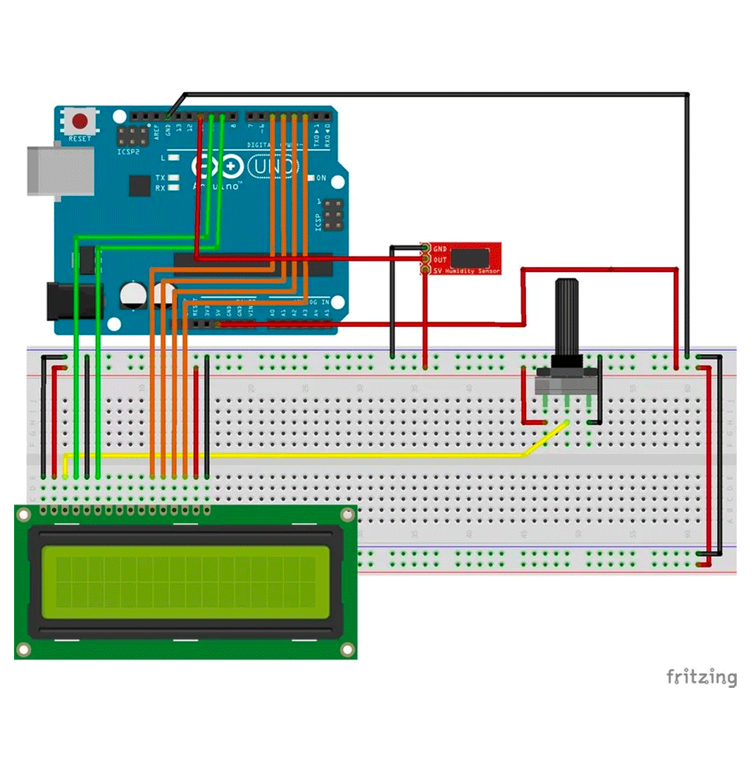 I searched for a model that had all of the components I was using, a DHT11 sensor, a LCD and a potentiometer.
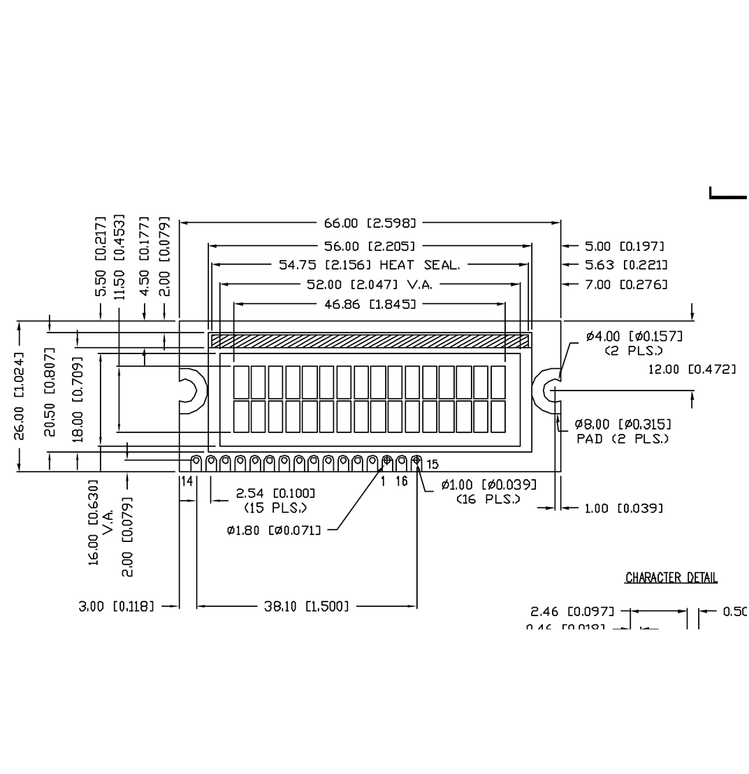
Using the datasheet as a guide I began setting up the pins for the LCD screen. It has 16 pins including several Ground and VCC pins that alternate depending on the model of the LCD screen.
It also has Vo (display contrast), RS (register select), R/W (read/write), E (enable), D0-D7 (data pins), A (anode) and K (cathode).
The Vo pin on which we can attach a potentiometer for controlling the contrast of the display.
The RS pin or register select pin is used for selecting whether we will send commands or data to the LCD.
The R/W pin will be used for writing or sending commands and data to the LCD.
The E pin is for activating the capability to write to the registers (8 data pins).
The A and K pins are to work the LED back light.
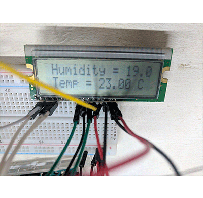
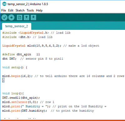
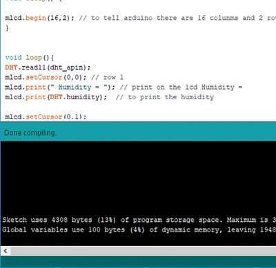
I inserted the Liquid Crystal Library and downloaded the code that would allow me to begin printing information on the LCD. I programmed the input information from the DHT sensor to be displayed on the LCD. Once I uploaded the information to my board, I saw flickering on the LCD.
I reconnected some pins to the potentiometer and I was able to get the screen to display the sensor information from my input.
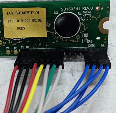
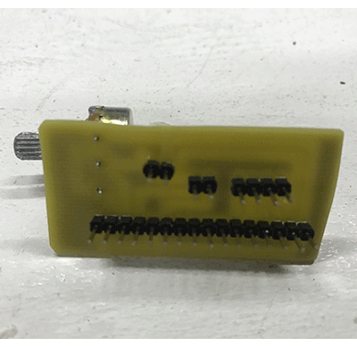
At first, I had some trouble with the board and pin labeling and had to write out conversion sheets. Mainly because the pin configuration for my board was 15 16 1 2 3 4 5 6 7 8 9 10 11 12 13 14, instead of 1 - 16. I realized that with what I had learned in the previous weeks, I could make a translation board for students to connect their board to. I could also attach the potentiometer to it to make it easier to place/connect for the user of my final project.
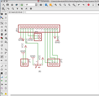
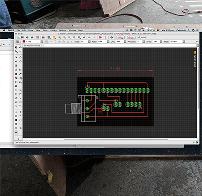
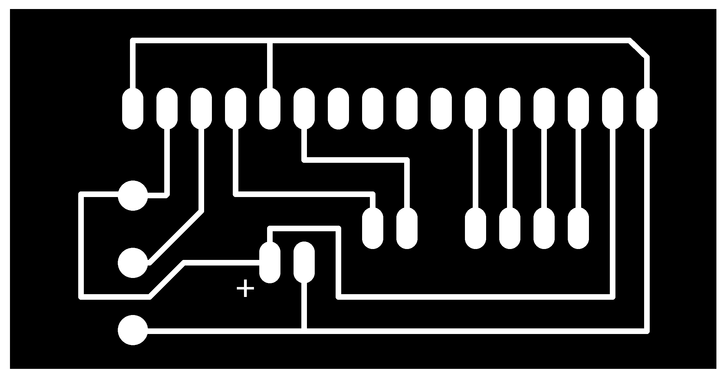
I imported the components into Eagle and designed the board. The Fab Lab inventory comes with an LCD screen that has pins 15 and 16 as #1 and #2.
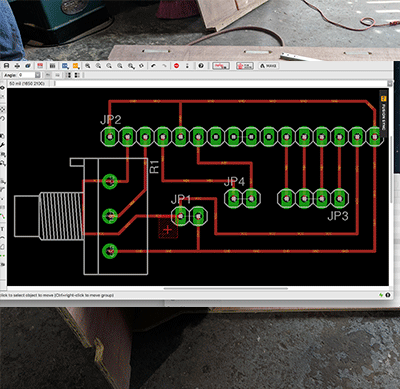
I placed the components in the schematic workspace and line up the ground and voltage circuits, with pins connecting to the corresponding ports and a pin connecting to the board I would have to build.
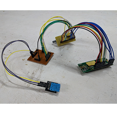
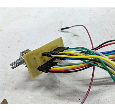
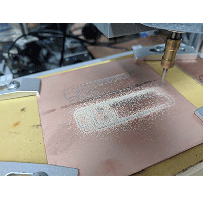
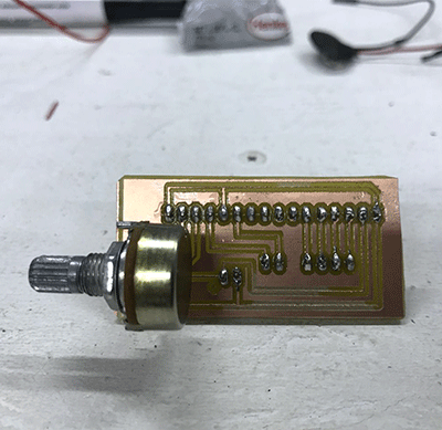
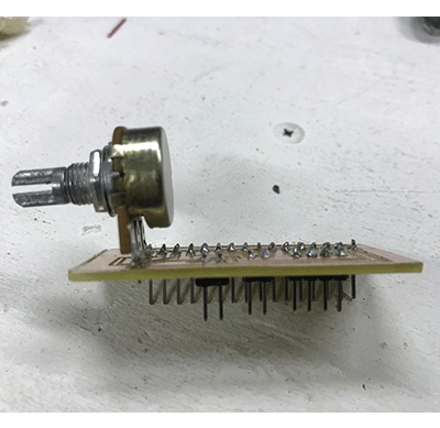
I cut the board and assembled the components taking into consideration that the LCD screen would be side mounted on a box so it would be better to not be fixed directly to the board.
After optimizing and getting my board connected, I set the port and board and uploaded the code and was able to read the data on the lcd.
1- measure the power consumption of an output device
Individual Assignment
1- add an output device to a microcontroller board you've designed and program it to do something
Software Used
<Tutorial Used
Fab Academy Week 11 - Output Devices Instructables InstructablesFiles used:
Display Board .BRD DownloadDisplay Board .SCH Download
LCD readout .INO Download
Walkthrough
First I familiarized myself with the components I would be working with.
(1) potentiometer
(1) lcd display
I found tutorials online that showed potential pin connections and if I encountered any pins I wasn't sure of I looked for other examples.
I searched for a model that had all of the components I was using, a DHT11 sensor, a LCD and a potentiometer.
Using the datasheet as a guide I began setting up the pins for the LCD screen. It has 16 pins including several Ground and VCC pins that alternate depending on the model of the LCD screen.
It also has Vo (display contrast), RS (register select), R/W (read/write), E (enable), D0-D7 (data pins), A (anode) and K (cathode).
The Vo pin on which we can attach a potentiometer for controlling the contrast of the display.
The RS pin or register select pin is used for selecting whether we will send commands or data to the LCD.
The R/W pin will be used for writing or sending commands and data to the LCD.
The E pin is for activating the capability to write to the registers (8 data pins).
The A and K pins are to work the LED back light.
I inserted the Liquid Crystal Library and downloaded the code that would allow me to begin printing information on the LCD. I programmed the input information from the DHT sensor to be displayed on the LCD. Once I uploaded the information to my board, I saw flickering on the LCD.
I reconnected some pins to the potentiometer and I was able to get the screen to display the sensor information from my input.
At first, I had some trouble with the board and pin labeling and had to write out conversion sheets. Mainly because the pin configuration for my board was 15 16 1 2 3 4 5 6 7 8 9 10 11 12 13 14, instead of 1 - 16. I realized that with what I had learned in the previous weeks, I could make a translation board for students to connect their board to. I could also attach the potentiometer to it to make it easier to place/connect for the user of my final project.
I imported the components into Eagle and designed the board. The Fab Lab inventory comes with an LCD screen that has pins 15 and 16 as #1 and #2.
|
|
|
I placed the components in the schematic workspace and line up the ground and voltage circuits, with pins connecting to the corresponding ports and a pin connecting to the board I would have to build.

|
|
I cut the board and assembled the components taking into consideration that the LCD screen would be side mounted on a box so it would be better to not be fixed directly to the board.
|
|
|
|
After optimizing and getting my board connected, I set the port and board and uploaded the code and was able to read the data on the lcd.