Week 4
Electronics production
assignment
Group Assignment
- characterize the specifications of your PCB production process
Individual Assignment
- make an in-circuit programmer (ATtiny45) by milling the PCB, then optionally trying other processes
How to Assemble & Program the FabISP


2- Shapeoko Router Kit. This machine was assembled as a kit and is run using grbl controller.
3- A desktop milling kit that one of our colleagues Michael saved the day with. He ordered it and assembled it and we were able to produce usable boards with it.
Hello ISP 44 Traces Download
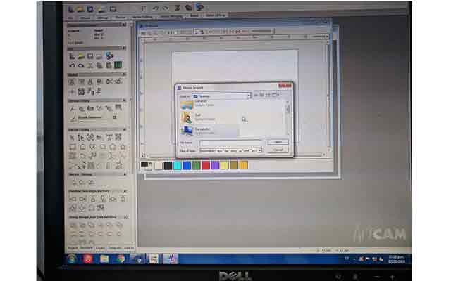
I opened ArtCAM for the very first time and was a bit overwhelmed by all the options. For now I would stick to the assignment.
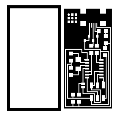
I imported the vector information of the board into the drawing space. I selected the profiling menu to set parameters of what I needed to cut.
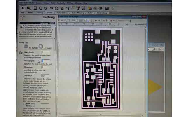
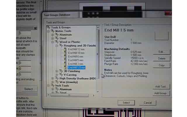
For the bit selection, I needed something that was small enough to cut the fine details between paths on the board. I chose the 1.5mm End Mill option.
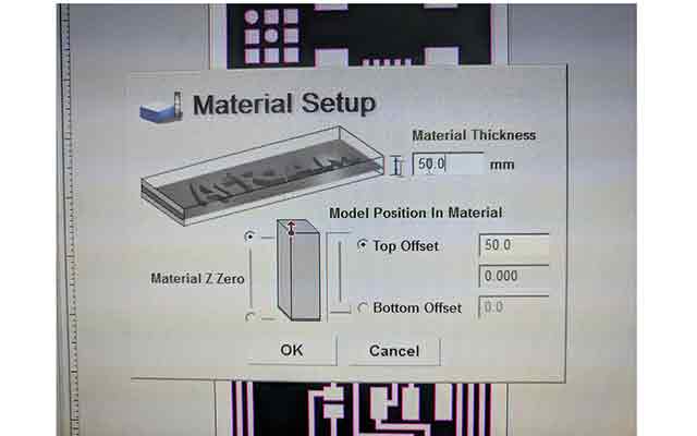
Another parameter that must be set is the material thickness. I can see how important it is to set this each time someone cuts something. In this case the values were stored from a previous project so they had to be adjusted to 3cm. After this I exported the GCode and was ready to mill.
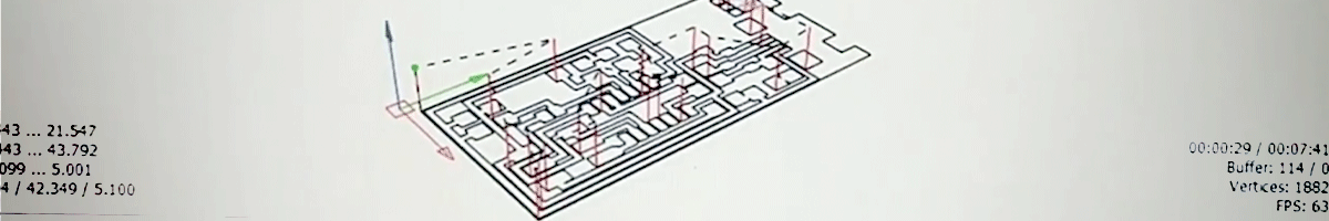
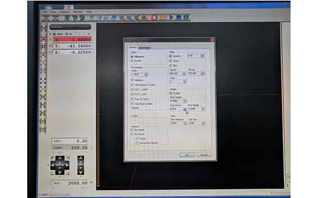
In CNC USB Controller, I imported the GCode.
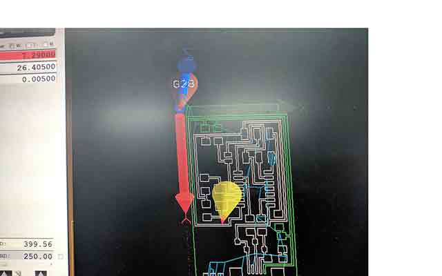
This showed the path that the mini-mill would take to cut out the board.
After trying to cut on two different machines and 1/64 bits from Costa Rica, we got the DIY kit milling machine to cut out the ISP.
I was able to ask a friend at a local technological university to have them cut out the boards on a machine that a professor has.
STUFF IT
Components
1 ATTiny 44 microcontroller
1 Capacitor 1uF
2 Capacitor 10 pF
2 Resistor 100 ohm
1 Resistor 499 ohm
1 Resistor 1K ohm/ 1 Resistor 10K
one 6 pin header
1 USB connector
2 jumpers - 0 ohm resistors
1 Crystal 20MHz
2 Zener Diode 3.3 V
1 usb mini cable
1 ribbon cable
two 6 pin connectors
I sorted through our component cabinet and picked out the components necessary for the board.
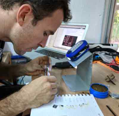
One by one, I began soldering the components onto the board, being careful to:
- orient and align components the right way
- place flux and minute amounts of solder on connection points before attempting to solder
I encountered many issues that had to be dealt with to comfortably work, including:
- uneven cuts in the board // re-mill the board
- tip cleanliness // file, scrape or sponge
- adequate work lighting // tie or build LED tower
- work station clamps // use makeshift safety pins
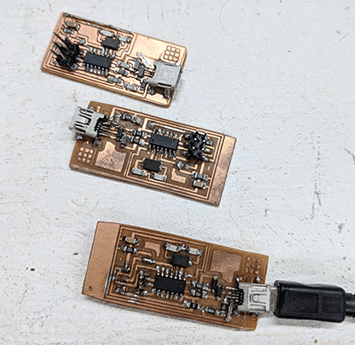
Soldering components onto the board.
My working board!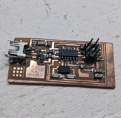
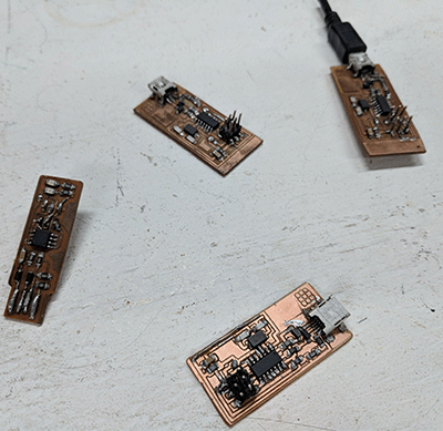
The board failure graveyard. This was before we had the AVRISP and I assumed that I had ruined a piece or a path so I made more.
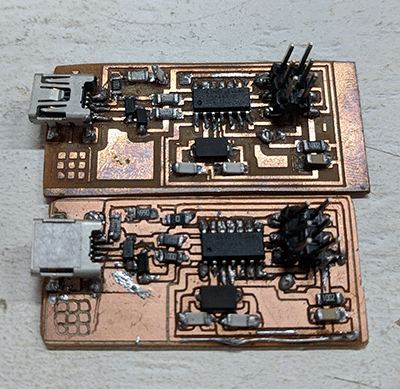
First attempts.
DEBUG IT
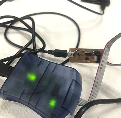
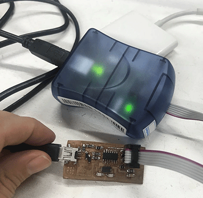
My first attempt to connect the board resulted in error messages. I re-checked my solder points and touched up on one that may not have been receiving a solid connection. At this point we were using a programmer that had 10 pins and so we ordered this one that was sure to work.
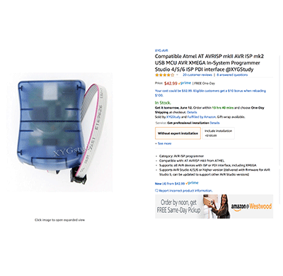
After connecting this programmer I was happy to find out that the light turned green, so I could proceed to the next step.
PROGRAM IT
After successfuly connecting the board to the computer, we tried to program it on my Macbook Pro.
I downloaded and installed Crosspack AVR. I also downloaded the firmware from the FabAcademy website and unzipped it to my website.
In the firmware folder, I opened the file called "Makefile" and edited the lines of code with the # and commented it out:
#AVRDUDE = avrdude -c usbtiny -p $(DEVICE) #
AVRDUDE = avrdude -c avrisp2 -P usb -p $(DEVICE)
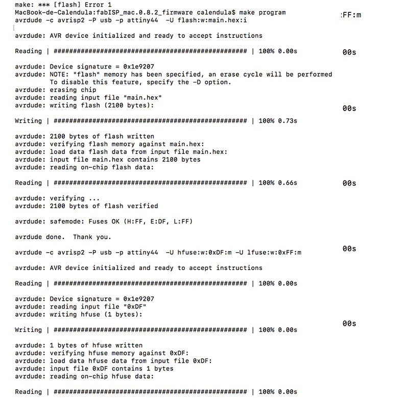
I was able to input the first and second commands:
make hex
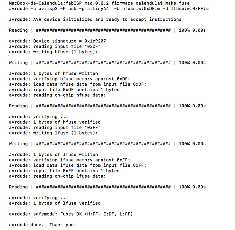
make fuse
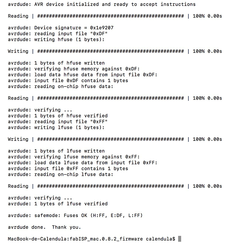
I was very pleased to be able to burn my first board even though I didn't know what it meant!
PCB production is fun and challenging and I am interested in exploring kits to build different types of arrays. With an upgrade to our milling machine and some improvements in our soldering stations we could produce kits for students or local schools to practice with.
I have seen other labs laser cut pcbs and I have heard of different processes using irons, black permanent markers and etching solutions. Maybe I will try it out for one of my assignments.
- characterize the specifications of your PCB production process
Individual Assignment
- make an in-circuit programmer (ATtiny45) by milling the PCB, then optionally trying other processes
Tutorial Used
Fab Academy Week 4 - Electronics ProductionHow to Assemble & Program the FabISP
Software Used
Art Cam, Grbl Controller, Adobe Illustrator, Google Chrome, Sublime Text, Photoshop, Git, Arduino
Tools Used
1- Xenotech CNC (donated by a jeweller who used it for coin engraving, it was run on a 19pin board and used Win 95 based program to operate. We couldn't install the port on a working computer with Win 95 so we replaced the controllers with USB controllers from Planet CNC.) This machine is a work in progress and was unable to cut the files we produced.2- Shapeoko Router Kit. This machine was assembled as a kit and is run using grbl controller.
3- A desktop milling kit that one of our colleagues Michael saved the day with. He ordered it and assembled it and we were able to produce usable boards with it.
Files used:
Hellos ISP 44 interior Download
Hello ISP 44 Traces Download
Walkthrough
MILL ITI opened ArtCAM for the very first time and was a bit overwhelmed by all the options. For now I would stick to the assignment.
I imported the vector information of the board into the drawing space. I selected the profiling menu to set parameters of what I needed to cut.
For the bit selection, I needed something that was small enough to cut the fine details between paths on the board. I chose the 1.5mm End Mill option.
Another parameter that must be set is the material thickness. I can see how important it is to set this each time someone cuts something. In this case the values were stored from a previous project so they had to be adjusted to 3cm. After this I exported the GCode and was ready to mill.
In CNC USB Controller, I imported the GCode.
This showed the path that the mini-mill would take to cut out the board.
After trying to cut on two different machines and 1/64 bits from Costa Rica, we got the DIY kit milling machine to cut out the ISP.
I was able to ask a friend at a local technological university to have them cut out the boards on a machine that a professor has.
STUFF IT
Components
1 ATTiny 44 microcontroller
1 Capacitor 1uF
2 Capacitor 10 pF
2 Resistor 100 ohm
1 Resistor 499 ohm
1 Resistor 1K ohm/ 1 Resistor 10K
one 6 pin header
1 USB connector
2 jumpers - 0 ohm resistors
1 Crystal 20MHz
2 Zener Diode 3.3 V
1 usb mini cable
1 ribbon cable
two 6 pin connectors
I sorted through our component cabinet and picked out the components necessary for the board.
One by one, I began soldering the components onto the board, being careful to:
- orient and align components the right way
- place flux and minute amounts of solder on connection points before attempting to solder
I encountered many issues that had to be dealt with to comfortably work, including:
- uneven cuts in the board // re-mill the board
- tip cleanliness // file, scrape or sponge
- adequate work lighting // tie or build LED tower
- work station clamps // use makeshift safety pins
Soldering components onto the board.
My working board!
The board failure graveyard. This was before we had the AVRISP and I assumed that I had ruined a piece or a path so I made more.
First attempts.
DEBUG IT
My first attempt to connect the board resulted in error messages. I re-checked my solder points and touched up on one that may not have been receiving a solid connection. At this point we were using a programmer that had 10 pins and so we ordered this one that was sure to work.
After connecting this programmer I was happy to find out that the light turned green, so I could proceed to the next step.
|
|
PROGRAM IT
After successfuly connecting the board to the computer, we tried to program it on my Macbook Pro.
I downloaded and installed Crosspack AVR. I also downloaded the firmware from the FabAcademy website and unzipped it to my website.
In the firmware folder, I opened the file called "Makefile" and edited the lines of code with the # and commented it out:
#AVRDUDE = avrdude -c usbtiny -p $(DEVICE) #
AVRDUDE = avrdude -c avrisp2 -P usb -p $(DEVICE)
I was able to input the first and second commands:
make hex
make fuse
I was very pleased to be able to burn my first board even though I didn't know what it meant!
Conclusion
With the help of tools like Fab Modules I was able to export a GCODE script for our milling machine to accurately cut out the ISP. There are other softwares like ArtCAM that allow you to generate GCODE for different machines and there are thousands of filetypes that are associated with different softwares. We found three that we will be using with our machines because they are easy to work with.PCB production is fun and challenging and I am interested in exploring kits to build different types of arrays. With an upgrade to our milling machine and some improvements in our soldering stations we could produce kits for students or local schools to practice with.
I have seen other labs laser cut pcbs and I have heard of different processes using irons, black permanent markers and etching solutions. Maybe I will try it out for one of my assignments.