MACHINE DESIGN
INTRODUCTION:
For the coming 2 weeks the assignment is to collaborate and work as a team to design a machine mechanically in the FIRST WEEK then to automate it in the SECOND WEEK.
HOW DID WE START?
To start the assignment we needed first to agree as a team on what we want to create, we sit together after the lecture where we did a quick brainstorming and listed all the ideas.
Several ideas were suggested.. like:
- Solar cell seeker.
- DIY candy machine
- Coffee art machine.
- Sand Art Machine.
- Plotter
- Foam Cutter
PROBLEM DEFINITION AND DECIESION:
We discussed the difficulties of each project and how can we achieve each one as a group project.
- Solar cell seeker: Although a lot of us were interested in this project but at the end we agreed that we will not learn much in this project and we favored going to another project where we can learn something new and be more challenged.
- DIY candy machine: We found that a lot of the parts needed can not be fabricated using 3d printing as it will be subject to temperature and it is also hard to do them via molding as we needed a material that is healthy and can be safely used with food.
- Sand Art Machine: It would be hard to maintain solid flow of sand particles and can be somehow problematic.
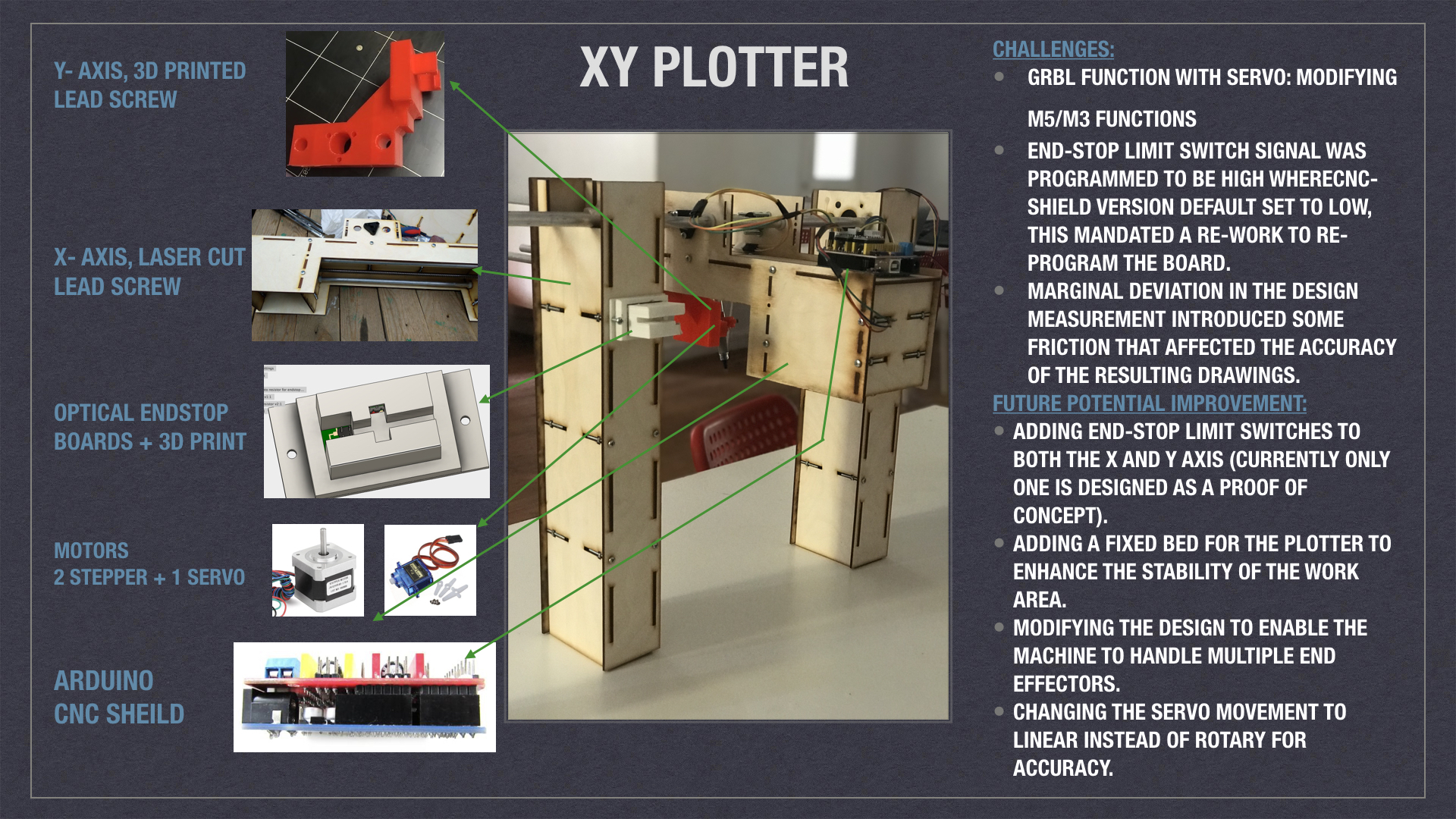
- Plotter: We decided to go with this option and add to it a feature where the end effector can be exchangable!.
So, we decided to look at different approaches to create the PLOTTER and we created an issue where we posted all the suggestions and we voted for each approach / mechanism.
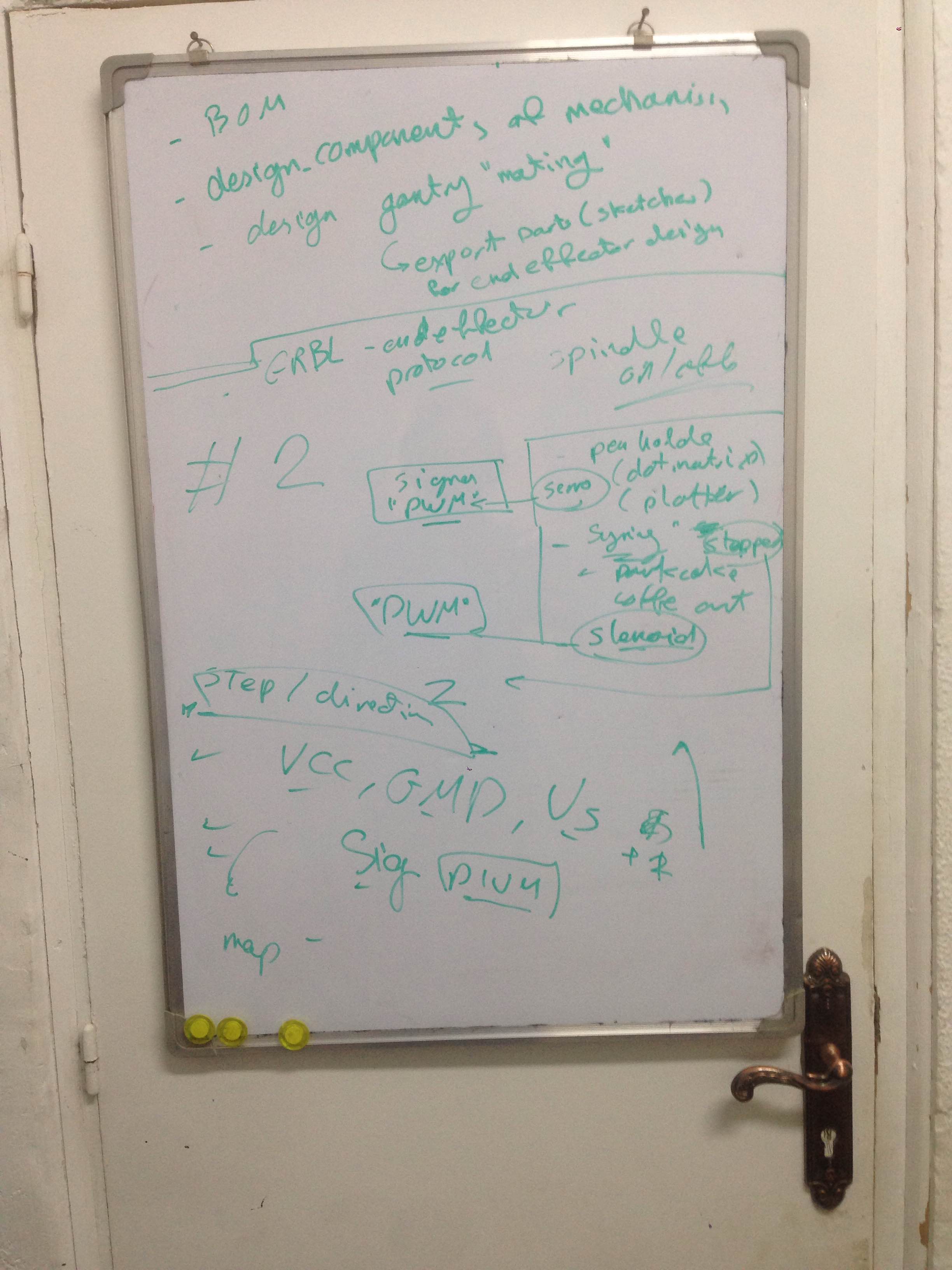
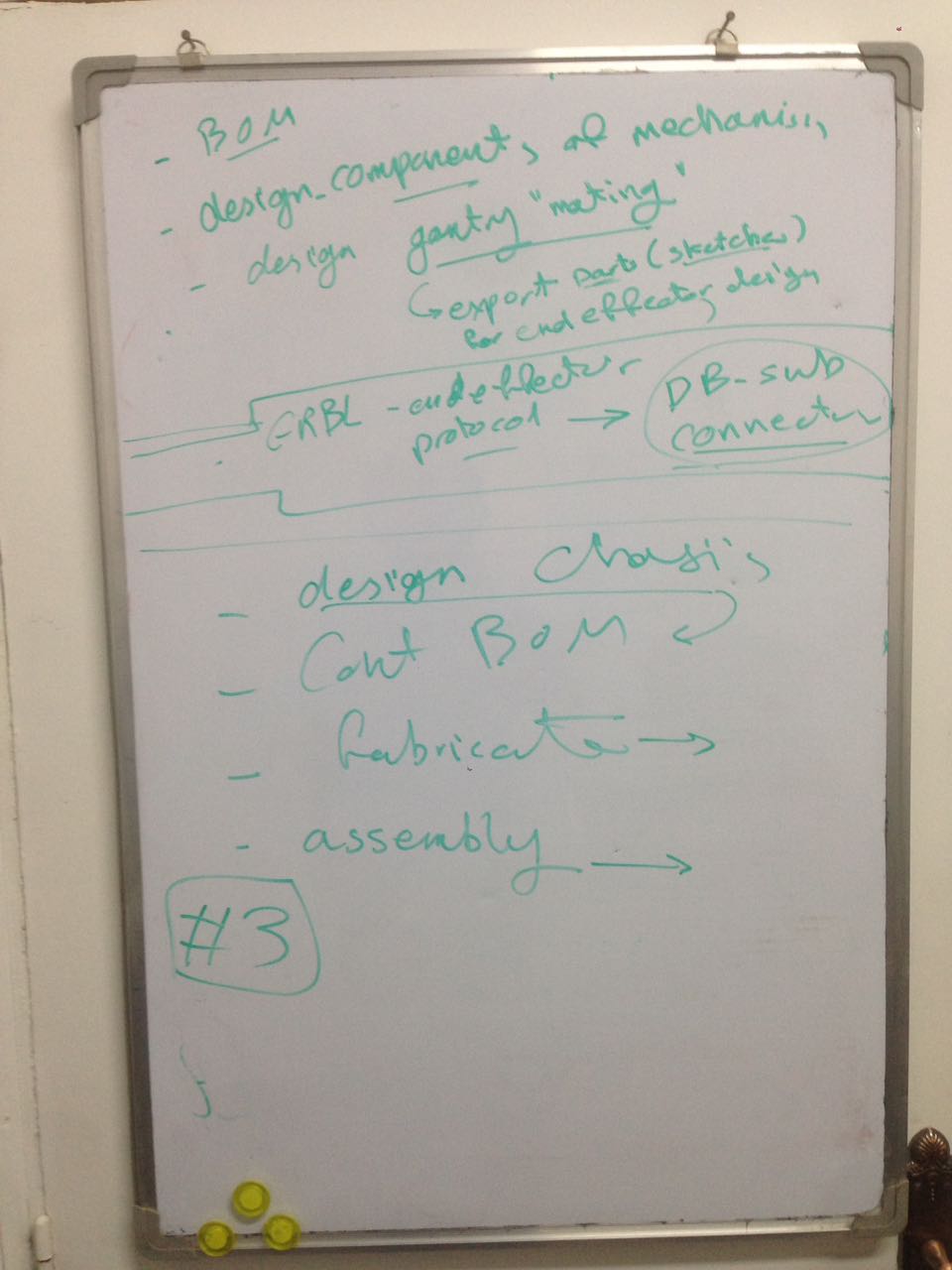
MEETING:
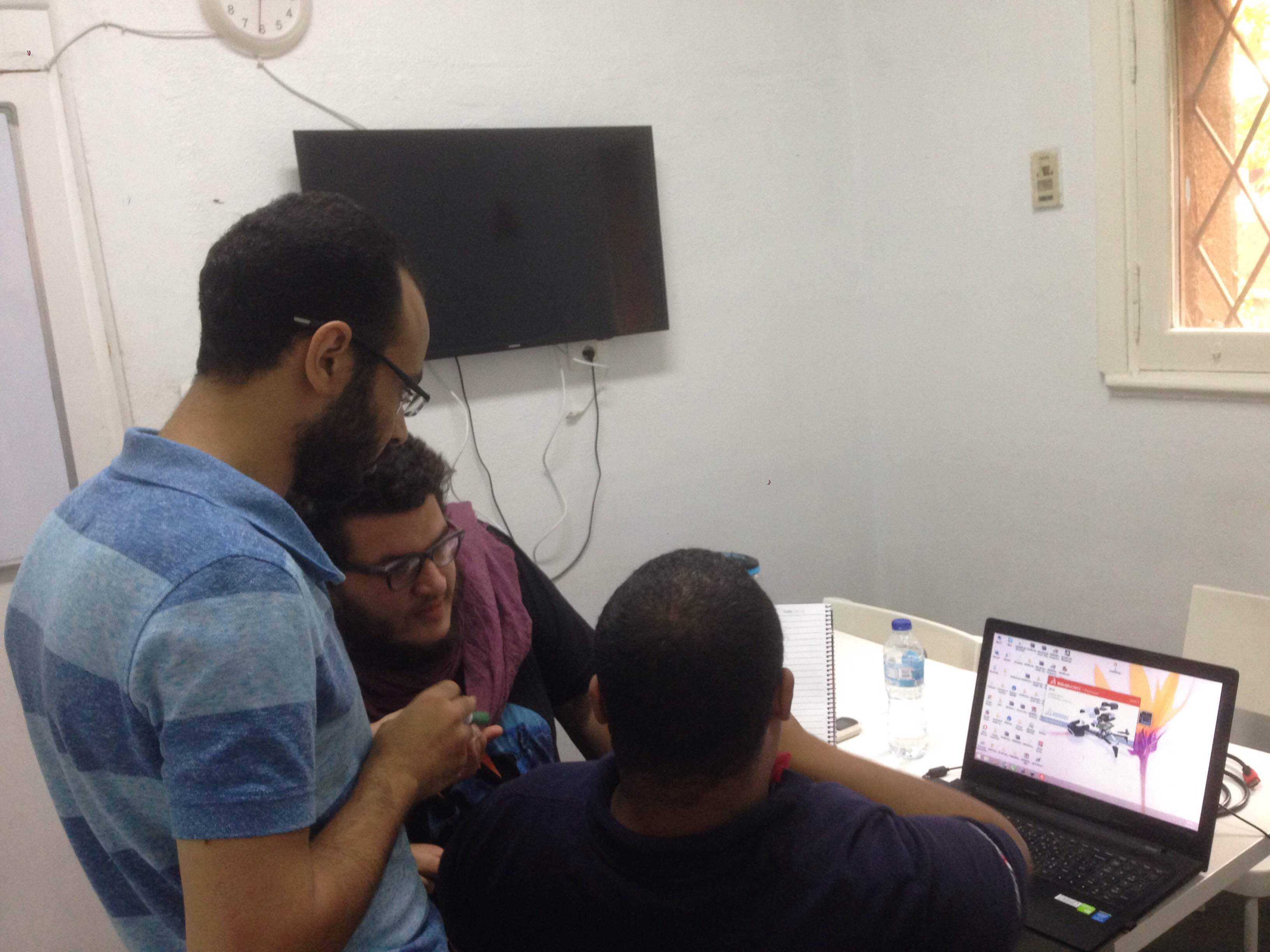
We arranged a hangout web meeting to discuss the approach and create a plan to work.
In this meeting we achieved the following:
- We finalized the overall view of the machine.
- We agreed on the mechanism and the body structure features as below:
- The chaisses should be something like THIS.
- Adjustable Height.
- End Effector should be exchangeable.
- We chose the Motor we will use (2 Nima17 Stepper motors for X-axis and Y-axis and one SERVO motor for the Z-axis.
- We favored the arduino, GRBL and CNC-SHIELD over Geshtalt because:
- Easier to find documentatuion for.
- Easier to process.
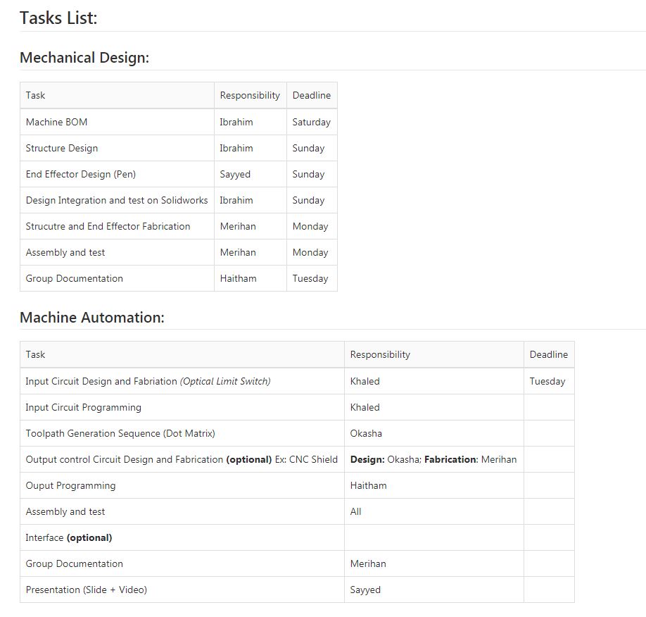
- We also set task-list to identify clear task ownership and target dead-lines as issues and markdown documents in a gitlab project shown in the screenshot below:
We also had a meeting where we did dicuss the details and tasks dependancy as well as going deeply into the details of the design.
Input Circuit Design and Fabrication (Optical Limit Switch):
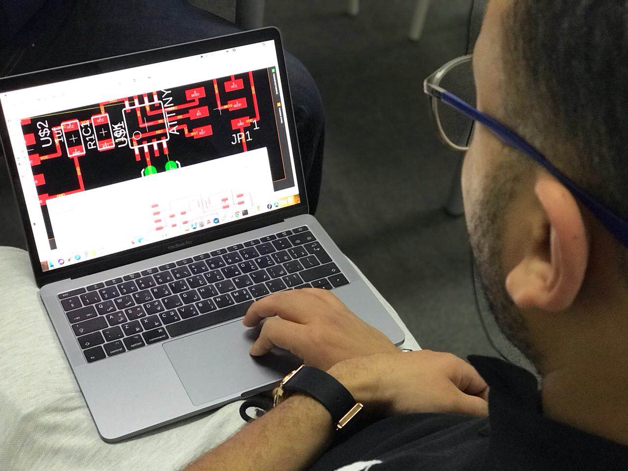
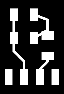
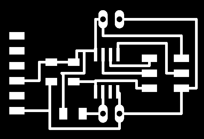
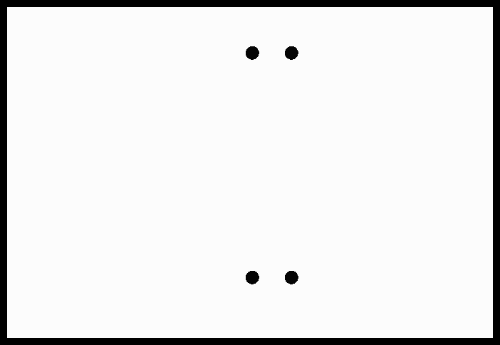
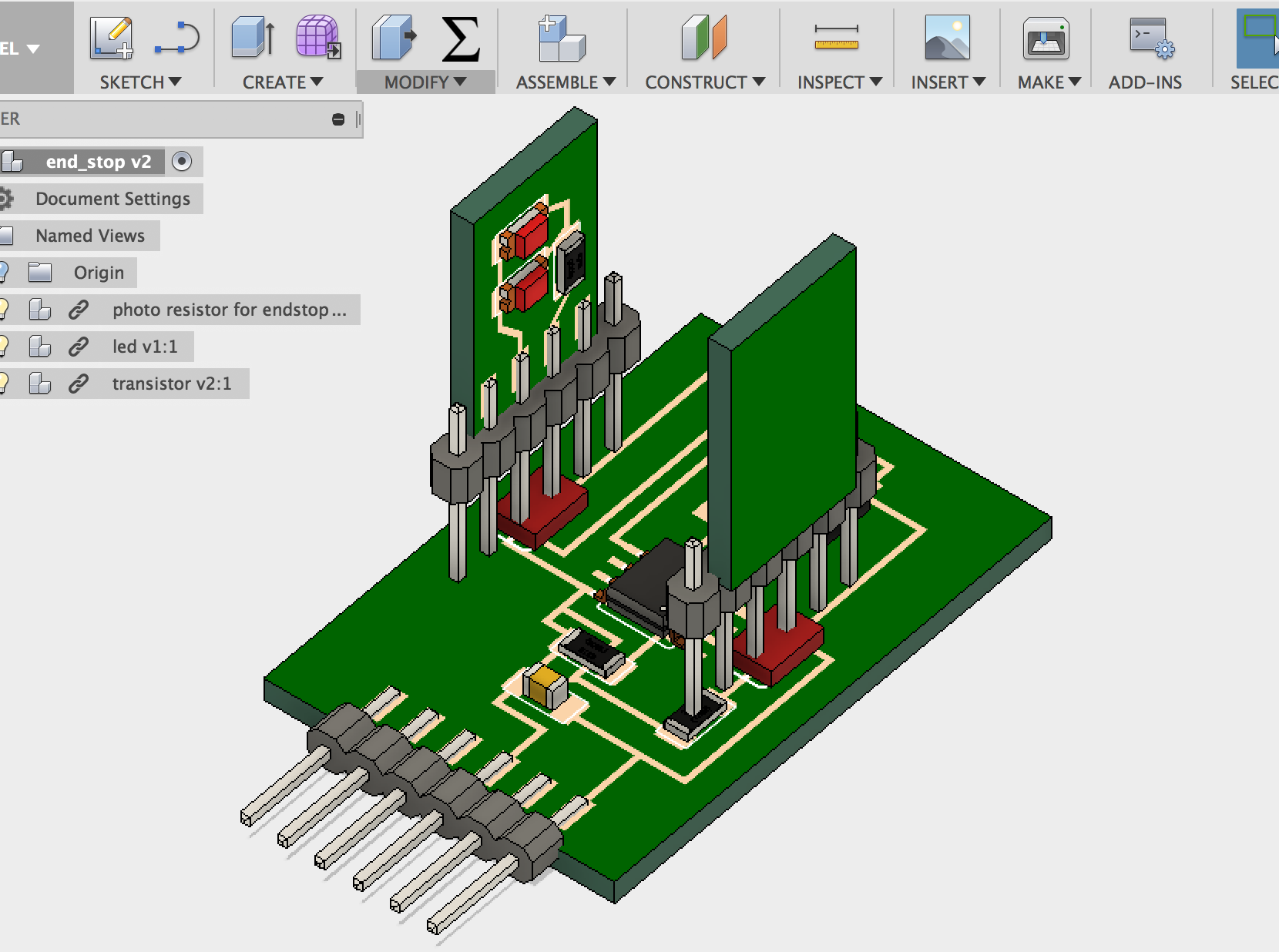
We Decided to design and fabricate two optical end stop switches, one for each axis for homing of the machine. The Idea is to make a 3 boards one with the MCU and the Pin heads for connections and one holding two leds and one holding the Phototransistor sensor, then connecting the 3 boards where the led board is facing the phototransistor board, then making a case with a space between the two boards so any object passing between the led and the phototransistor will change the value of the sensor. we will use the change in the value of the sensor to send digital signal to the main board of the machine to act as the end stop signal.
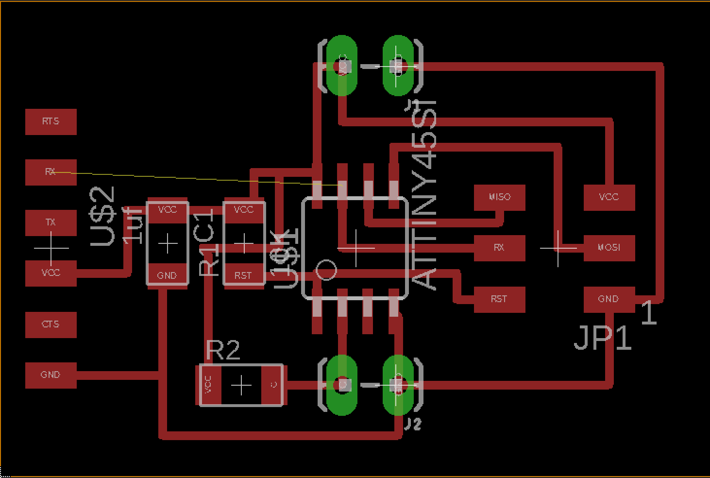
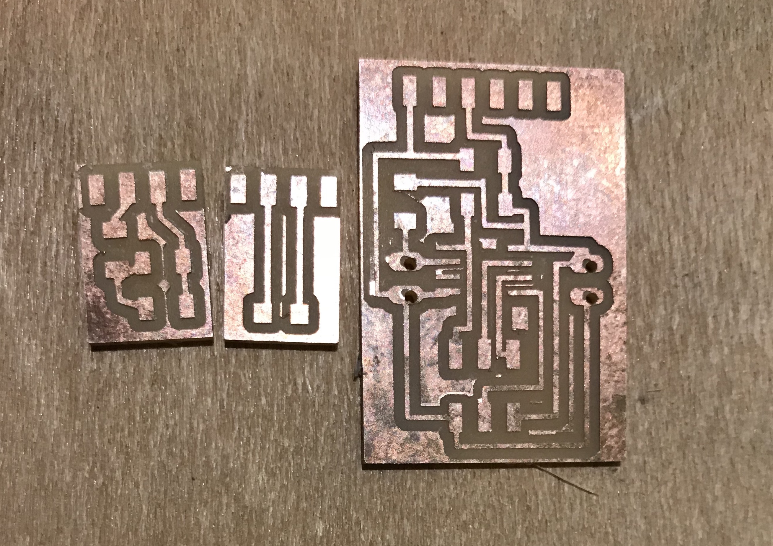
Khaled designed the boards on eagle and fabricated them on the modela MDX20 and the list of Component as follows:
- 1 X ATtiny 45
- 1 X AVRISP
- 2 X 10Kohm Resistors
- 1 X 1uf capacitor
- 1 FTDI pin header
- 2 X female through hole pinheads
- 2 X LED
- 1 X Phototransistor
As shown below the screen shots of the boards, Eagle files, Modella Files:

Finally the boards after being soldered are as below:
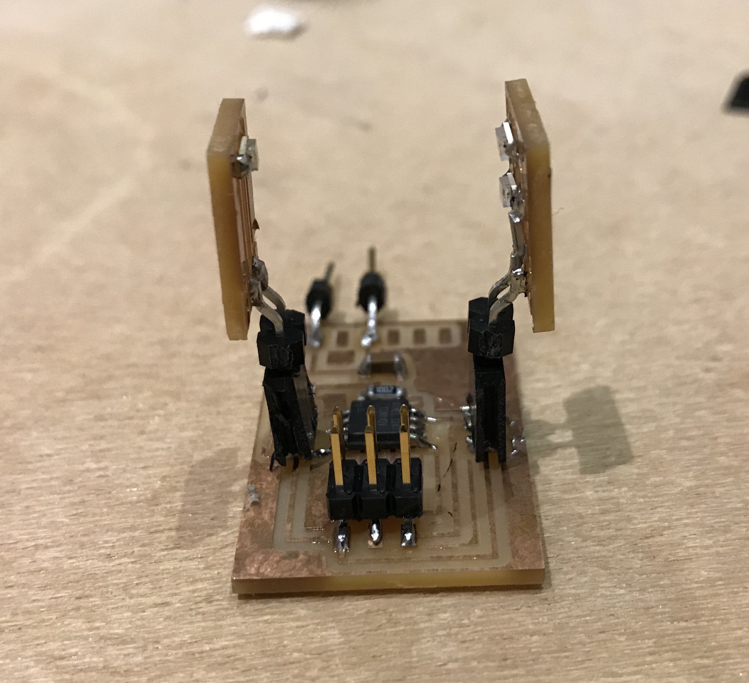
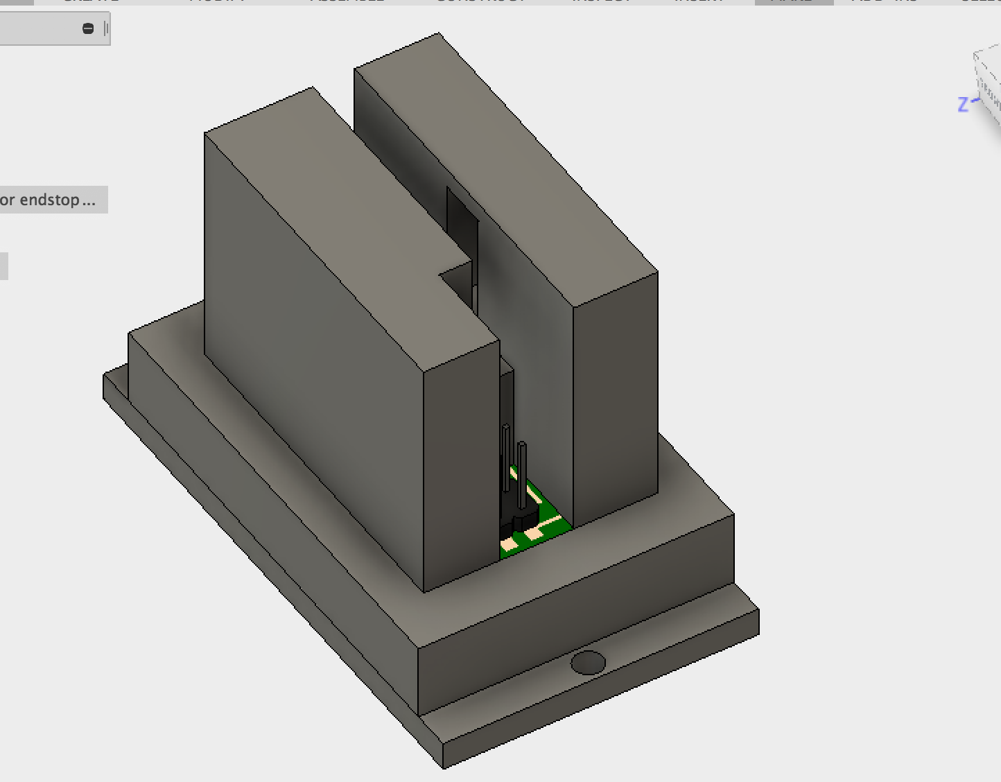
Khaled linked the boards from eagle to a fusion project and assembled the three of them to design a case for them.
he designed a casing for the assembled boards trying to minimize the effect to the ambient light on the sensors by making lEDs and the sensor facing each others, with total enclosure for both of them with only one opening on each facing each other.
exported the design as STEP file and sent it to Ibrahim to integrate it with the machine design.
He printed the the 2 parts together in the same print.
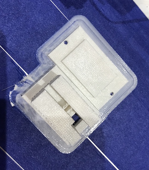
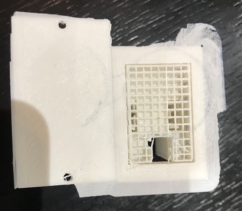
Then Assembled them
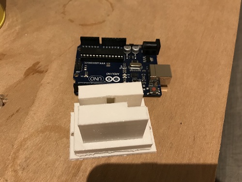
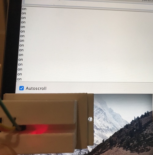
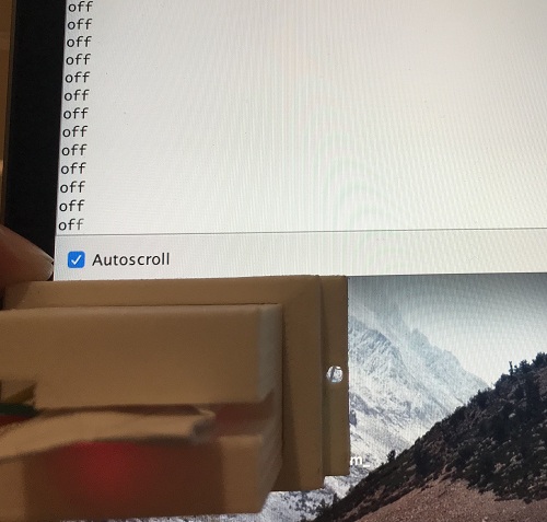
Finally, he tested it on Arduino, when the value exceed the threshold preset to 1000 the boards puts the digital pin high and serial print "OFF", otherwise digital pin low and serial print "ON" as you can see in the pictures below.
Input Circuit Design and Fabrication (Optical Limit Switch):
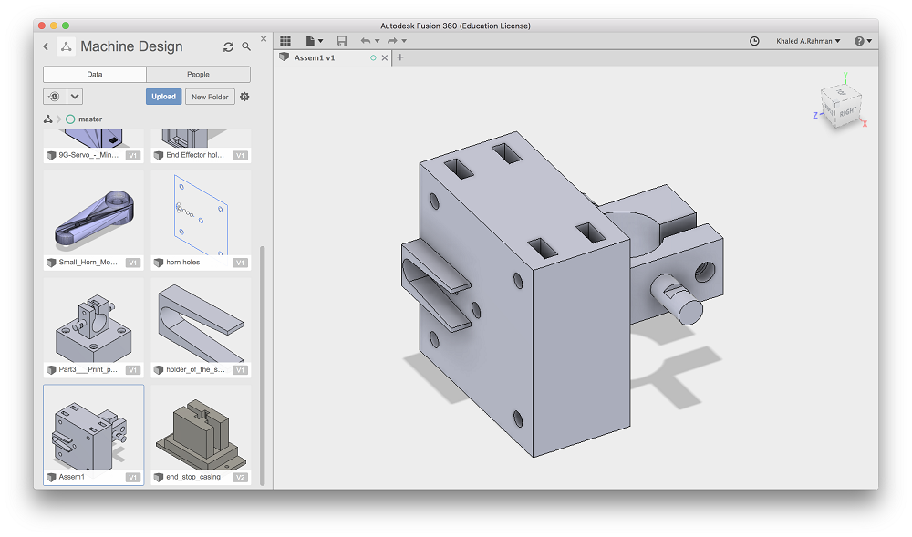
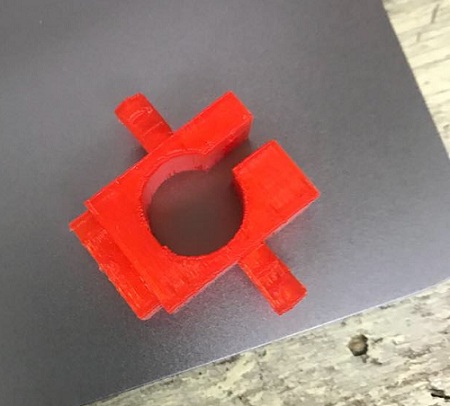
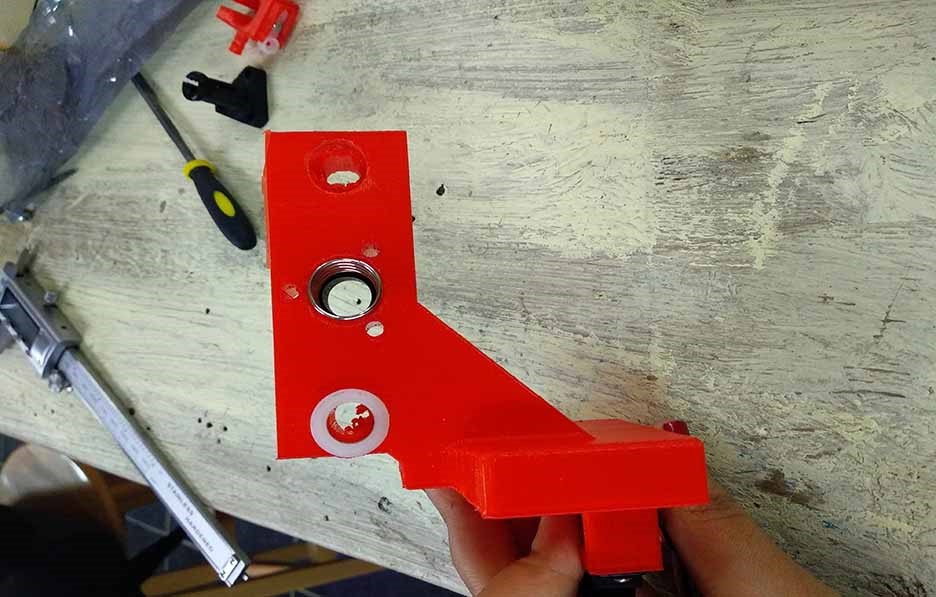
I (M.Sayyed) designed the end effector part which will hold the pen.
I started with looking around the internet for CNC plotters and look close how their end effector part works.
and idea of the end effector came to my mind through watching different designs.
So the idea of this sketch came to my mind which's a tightable holder for the pen.

and the idea esclated to make the part more robust and to connect to the chassis as Ibrahim and I talked.
I printed the basic part without the big block to test the concept itself.
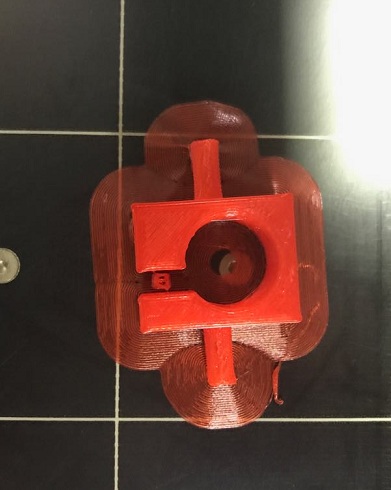
and the part needed modification to the nut slot, so I printed it again and it worked.
after that we modified the part again because of Ibrahim's hardware modification, and my colleague Khaled edited it.
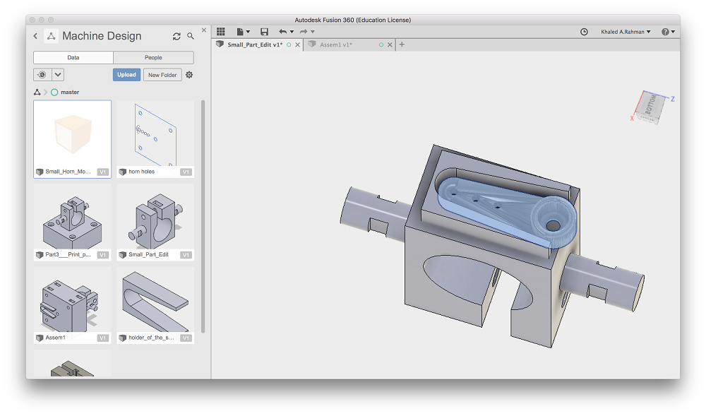
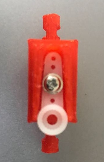
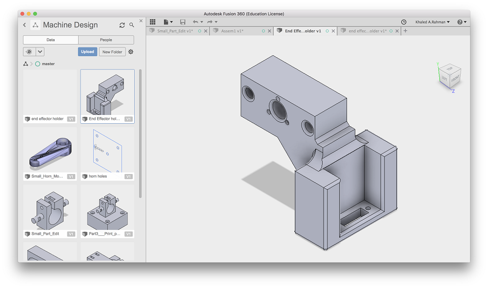
For the End effector "Pen holder": he have modified the design to make it lighter in order for the servo to be able to hold it, I removed the block in the middle and attached the holder for the servo motor horn directly to the pen holder.
Before Edit:
After Edit:
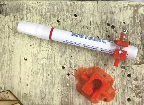
After printing:

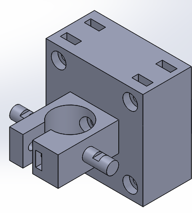
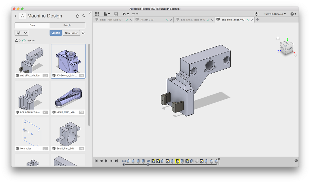
For the End effector holder: He changed the hooking mechanism, so made the back flat and added to elevated steps in order for the servo to fit between them and added to holes on top for the servo screws.
when I sent the STL to Cura slicer for 3d printing, the file required 6 hours for printing so he remodified the design removing all unnecessary spaces from the flat side and reduced the thickness of the holder, and succeeded to reduce the print time to 2.5 hours.
Before:
After:
After printing:
BOM:
| Count | Item | Store (URL) | Manufacturer URL | Price (EGP) | Price (USD) | Comments |
|---|---|---|---|---|---|---|
| 1 | GRBL (CNC Shield) | http://ram-e-shop.com/oscmax/catalog/product_info.php?products_id=2963 | https://blog.protoneer.co.nz/arduino-cnc-shield/ | - | ||
| 1 | Arduino Uno | - | - | - | - | - |
| 3 | DRV8825 STEPPER DRIVER | https://uge-one.com/3d-printer-stepstick-drv8825-stepper-driver.html | https://www.pololu.com/product/2133 | 70.00 | - | - |
| 1 | Micro Servo MSG90 | - | - | - | - | - |
| 2 | AQS Nema 17 stepper motor with in-built lead screw (4 starts-2mm pitch 8mm dia) | https://www.aliexpress.com/item/New-3D-Printer-NEMA-17-Lead-Screw-300mm-Stepper-Motor-Z-Axis-3D-Printer-KIT-Step/32579962696.html | http://mtm.cba.mit.edu/machines/science/doc/scienceBOM.pdf | - | 24.99 | Alternative link for the ones from MTM kit |
| N/A | Light Duty Dry-Running Sleeve Bearing, 1/16" Flange Thickness, Nylon, for 3/8" Diameter, 1/2" OD, 3/8" Length | https://www.mcmaster.com/#6389K625 | - | - | 0.83 | - |
| N/A | Anodized Architectural 6063 Aluminum Round Tube (Corrosion-Resistant, 0.07" Wall Thickness, 3/8" OD, 6 Feet Long) | https://www.mcmaster.com/#4568t22/=1cq6i5p | - | - | 10.07 | - |
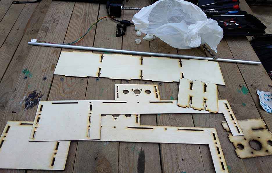
The mechanical designed was done by Ibrahim Elwy who dropped out and didn't document his part .. He designed the part in solidworks, exported the dxf files for laser cutting on 3mm plywood
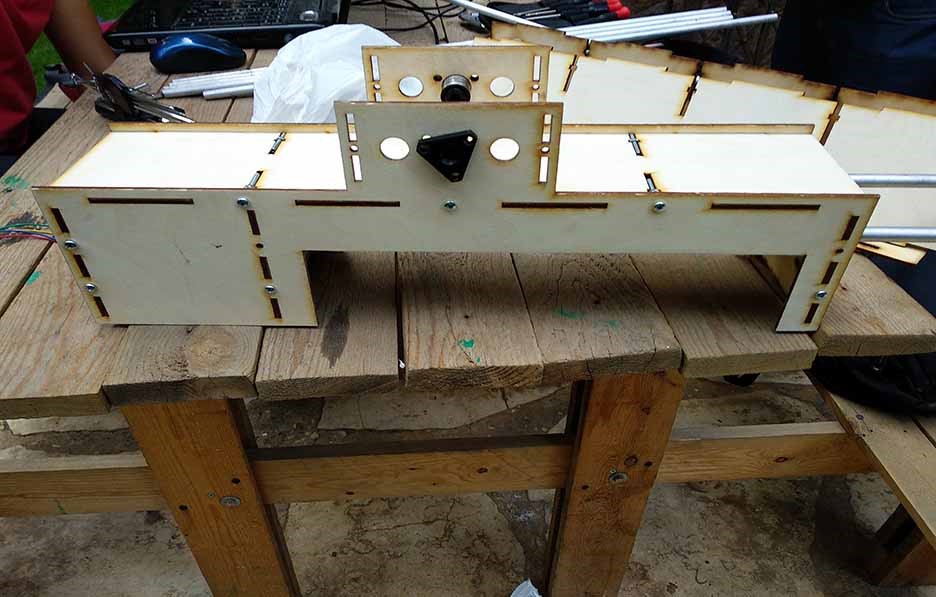
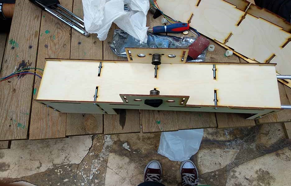
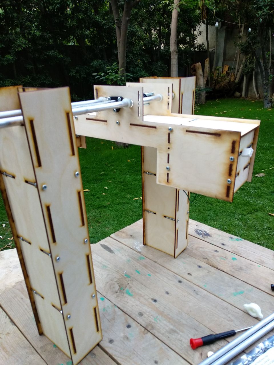
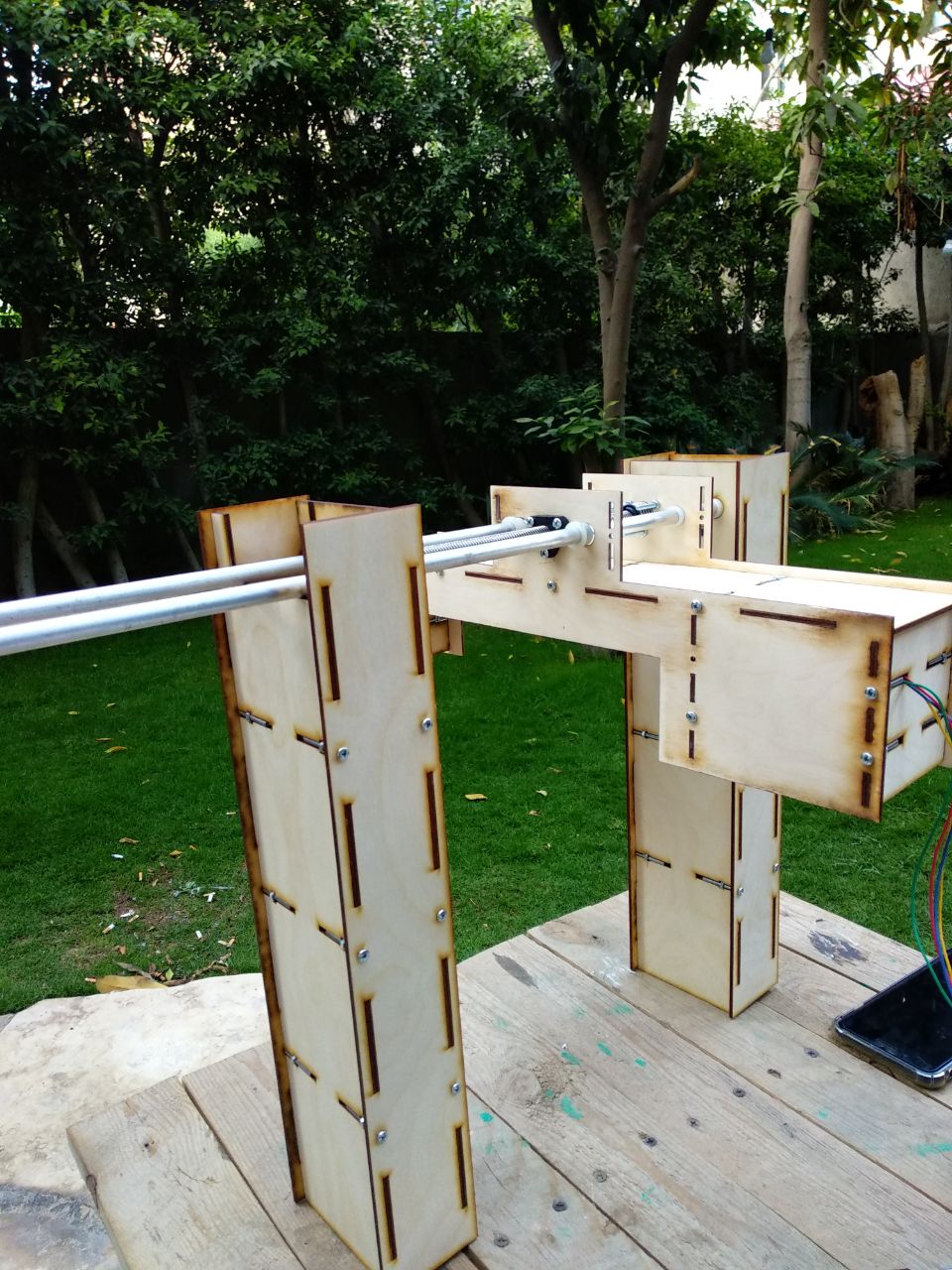
We managed to get the machine assembled and we got photos for the machine as below. It was great to see something thatyou built :-)
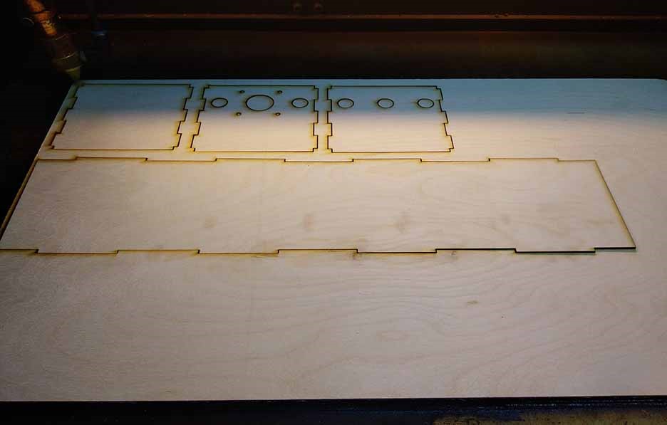
Step1: Laser cutting the chassis
I got the design from Ibrahimand cut it using 3mm plywood sheets and laser cutting machine
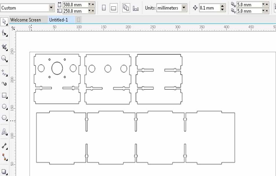
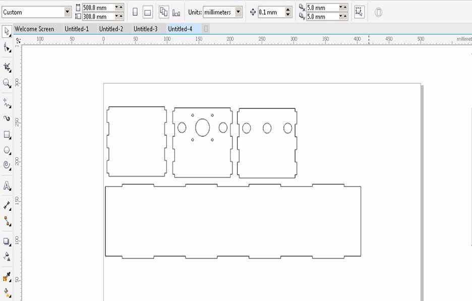
I opened the DXF files provided with coral draw program.
Arranged the parts on 30 x 50 cm area which it the maximum working area of our laser cutting machine.
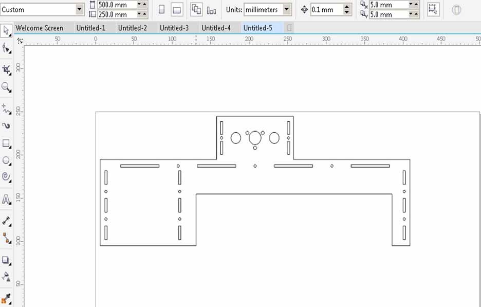
Arranged the rest of the parts
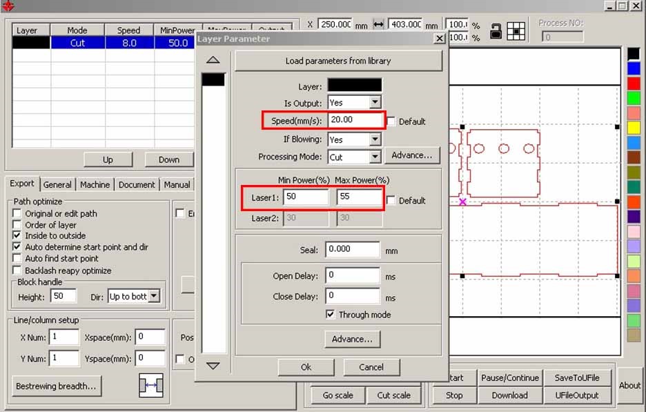
I then run the files to the lasercut software to adjust the suitable speed and power for the wood which is 20 mm/sec speed and 50% min power and 55% max power.
More details about our laser cutting machine and its softwares on Computer Controlled Cutting week.
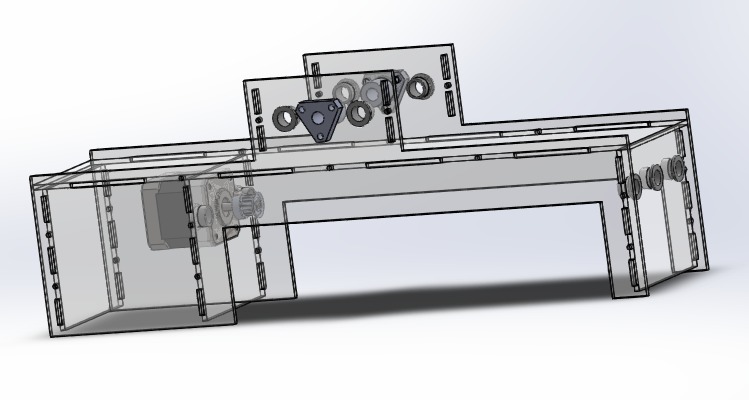
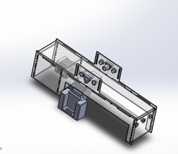
Step2: Assembling the chassis
The mechanisim constructs of X axis and Y axis to allow the x, Y movement.
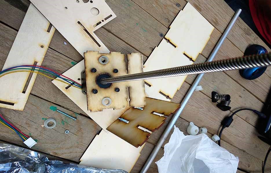
We used the MTM motors, Screws and nuts
We started the assembly process using screws and nuts to fit the chassis together and we used the MTM motors, lead screws and nuts for the x,y Movement.
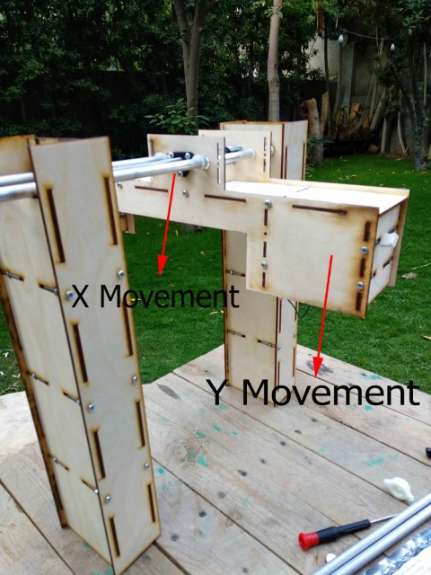
The Mechanisim showing the x,y Movement
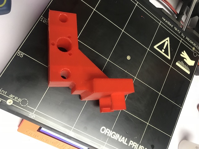
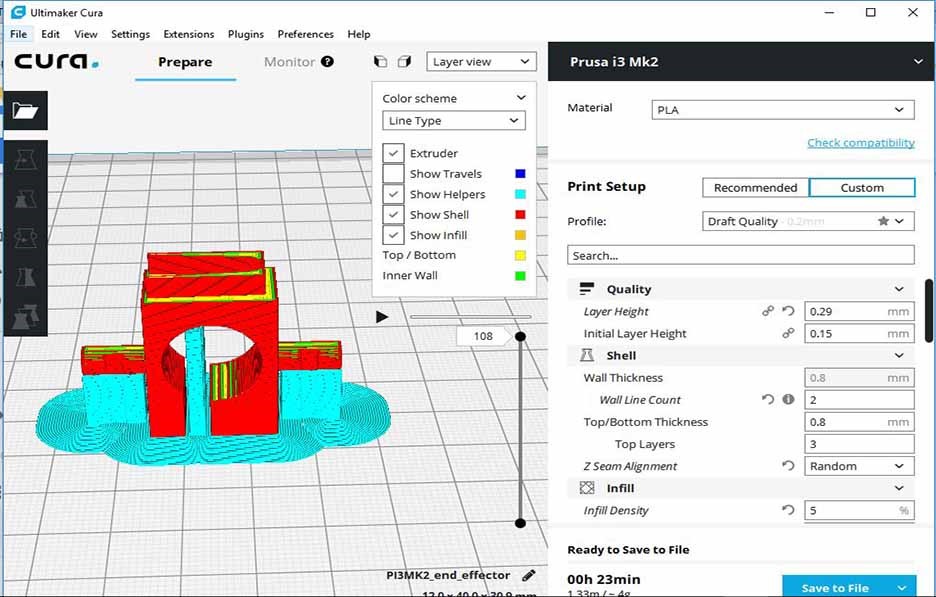
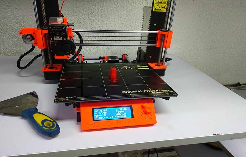
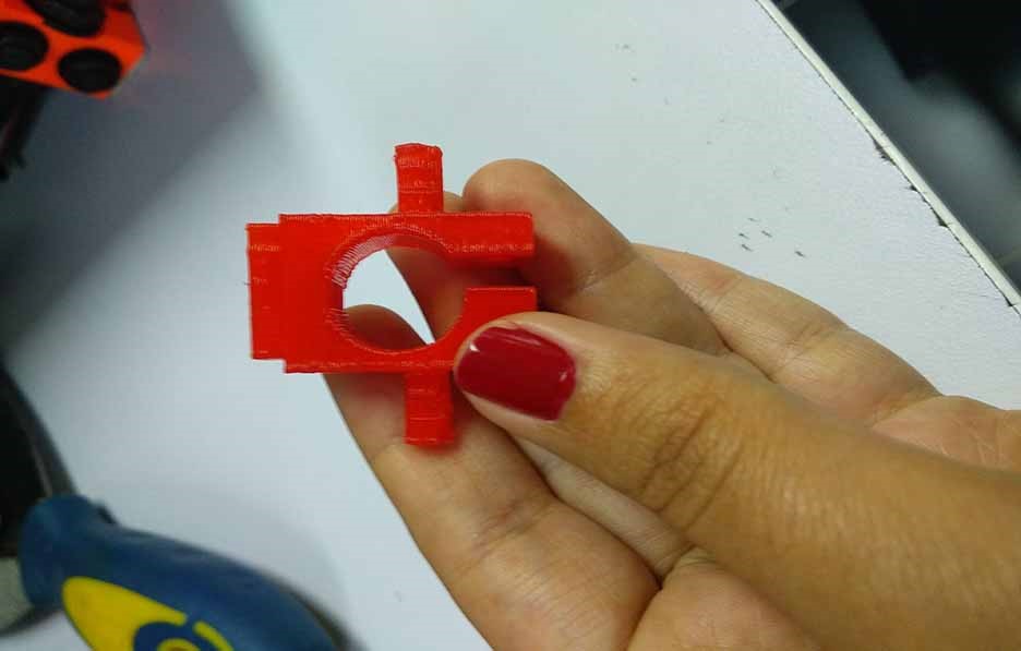
Step3: 3D print the end effector
I got the designs from my colleague Mohamed Elsayyed who designed the end effector and from Ibrahim who designed the end effector holder. I sliced it using ultimaker cura and the new prusa 3D printer we got. Didn't find any problems with the end effector it self but we faced some problems with the end effector holder. The holes were not right in size to be able to fix the nuts on it so we had to do a lot of sanding to make it fit at the end.
Below is a video that captures the machine mechanical movement tested.
MACHINE DESIGN:
After the machine and mechanical design was completeed we started to think how to automate it, Haithem responsible for OUTPUT programming part where he did the following sub-tasks:
- He Installed and connected the Arduino, CNC-Shield, Motor Drivers, Stepper Motors and Servo Motor.
- He Installed a modified GRBL firmware that supports the Servo motor named GRBL_MI
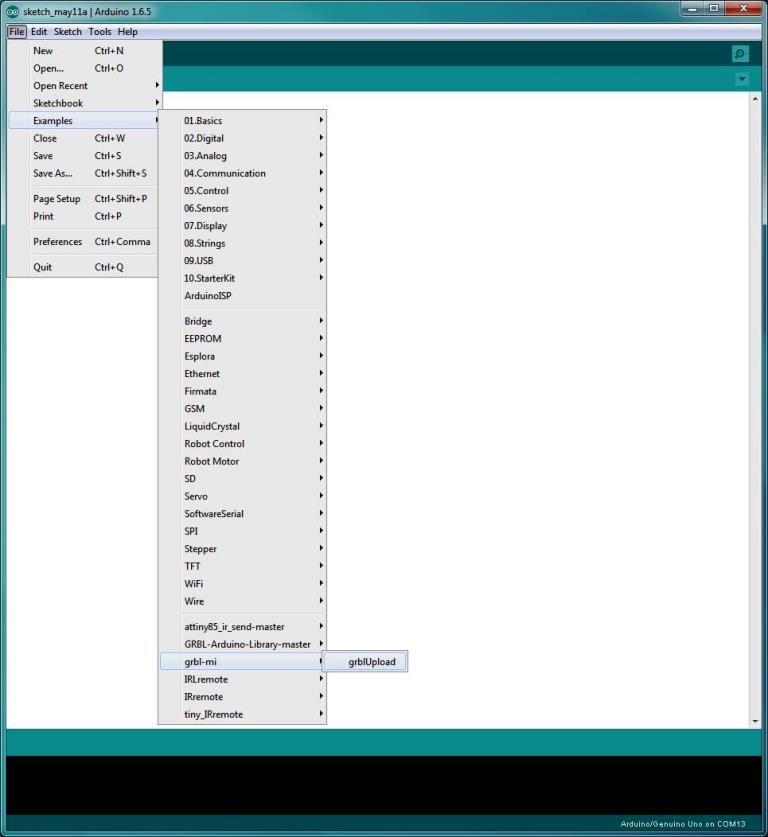
- Haithem Then installed an extension in Inkscape that enables us to draw a drawing and then export the drawing to G-Code that is supported by the MI-GRBL.
- He finally installed Universal G-Code Sender and he tested the G-Code by sending it to the CNC-Shiled and ensure that the steppers and the Servo motors are working fine.
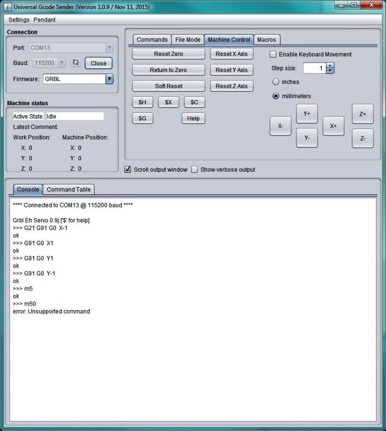
- Last step was to do and record the tests that he did as per the video below. More details about Haithem's work can be found in THIS URL
Interfacing with the machine:
For The interfacing with the machine, Okasha thought about the whole interface and how he can make is own interface. We thought about making a plotter that can draw pictures.
So he started thinking about Make 2 ways to convert a picture to G-code to the machine:
- Through the Camera of the laptop
- Through Importing a camera
Then he started generating from it a Gcode, and he went in this 2 ways to generate algorithm:
- Start Thinking Draw Pixels.
- Start Thinking about Draw Lines for the continues Pixels which is was better for making a small Gcode.
Then He started Testing the Machine ..He found that ..
There are a problem with the Y Problem “ The End Effector Connected to “ It cant handle a Very Small Steps after Configuring it with $101 = 10 For example …
So He didnt get the Values that going to Help him To make it Draw Pixels “ Resolution of the Machines Mfotors is Low and The Fricition of the machine Parts is High “
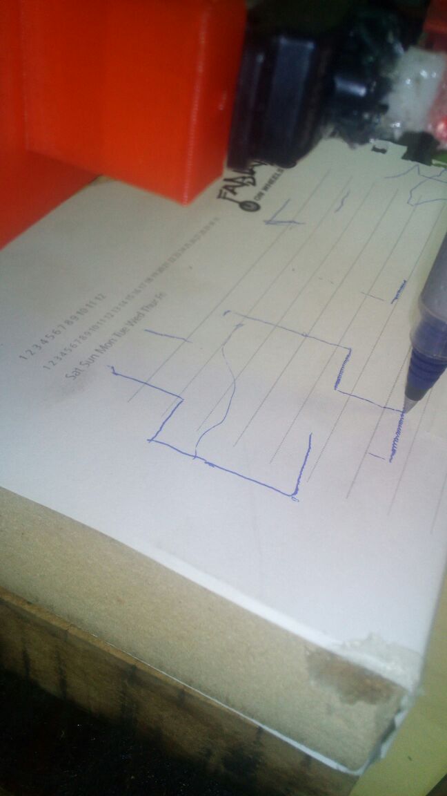
So he thought about Moving the machine From Serial so he Tried to draw a rectangle .. And the output was not bad .. So he thinked about using the equations that he used before in Openscad to draw a Shape on GRBL ..

So He make a New Code that can generate the GCODE from the Equations he Used Before ..
So Then he implemented it And Worked nicely .. and to understand more please refer to Okasha's website
End Effector rotation:
Before optimization:
After optimization:
Advanges that we did :
1) We make multiple ways to control the machine from writing Gcode manually to use Inkscape using Extenstion to use Python Generator Code to use Openscad Code to Use Impage processing and start generating Gcode for Pictures
2) We used a Different GRBL that Called MI GRBL that control Servo Motor instead of Stepper Motor in Z
3) We Make a Automatic Stop Sensor with a good mount in the machine and Working Great
4) The Pen Mount Was great But because It was damaged so we had to fix it manually to can works in Integration and Programming
challenges with the machine :
1) there were a problem with the mechanical Design that it was very high and without a fixed bed to work with ..
2) the design of the pen holder was cracked and we Fixed it Manually to get it work
3) there was a huge frictions between screws that can't help the motors do a small moves so we cant draw pictures on .. because the smallest step was 1 cm and all the bed the machine can cover is A4 paper
4) we didnt have a lot of details about the mechanical Design and Edit it as the one who was responsible for the assignment dropped out
5) the machine need to have a base to can stand at .. with any strong move the machine can fall dowm
Details About The File Attatched ..
Code 1 : Get Threshoulded Picture took alive from Built in Camera and Export from it a GCODE and Pixels color .. Is it a black or white ? ..
Code 2 : Sending alive Gcode to the GRBL and Machine start working ..
Code 3 : Generate a Gcode from Openscad’s Code “ Generating Points Of polygon For Example “ And start Drawing it easily ..
Code 4 and 5 : Took 2 Photos that can be 640 * 480 for the first code and Second Code is to be a Icon 24 * 24 And Generate the Gcode
Code 6 : There are 2 Algorithms First One draw pixel by Pixel .. Codeand the other one is getting the black lines and Drawing it ..
Issues You may Face :
1) Is the $100 and $101 Values To make the Machine Precise ? More Small Value is better to get a great value ..
2) Is their a Servo in the Design As here in Egypt we used the M5 and M3 S90 To control The servo ..
if the Pen is fixed There will be no Need to use M5 and M3 Codes ..
Recommendations :
Try to Use the Code of the Icon as It generate a Small Gcode and Make a quick Pilot for it
There is a Code Called the Perfect Code I recommend to use it ..
That is all
The link For Python Codes