WEEK 14 - EMBEDDED NETWORKING AND COMMUNICATIONS
INTRODUCTION
This week we are required to connect at least 2 boards using a communication medium and protocol. Last week I got more and more familiar wit hthe bluetooth protocol so I decided to choose bluetooth protocol to use this week.
Assignment Description
- GROUP ASSIGNMENT: To send a message between two projects.
- INDIVIDUAL ASSIGNMENT: To design and build a wired and/or wireless network connecting at least two processors.
Learning Outcomes
- Demonstrate workflows used in network design and construction.
- Implement and interpret networking protocols.
Have you (Checklist)
- ✔ Described your process using words/images/screenshots.
- ✔ Explained the programming process/es you used.
- ✔ Outlined problems and how you fixed them.
- ✔ Included original code.
STEPS PERFORMED:
TOOLS AND HARDWARE USED (COMPONENTS):
- 1 x FR1 (Copper PCB Board).
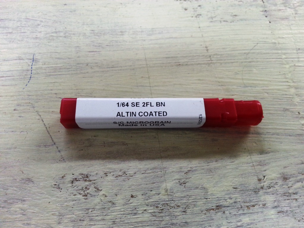
- 1 x 1/64 inch end mill bit.
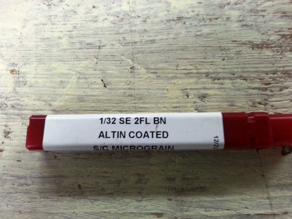
- 1 x 1/32 inch end mill bit.
- 1 x double tape.
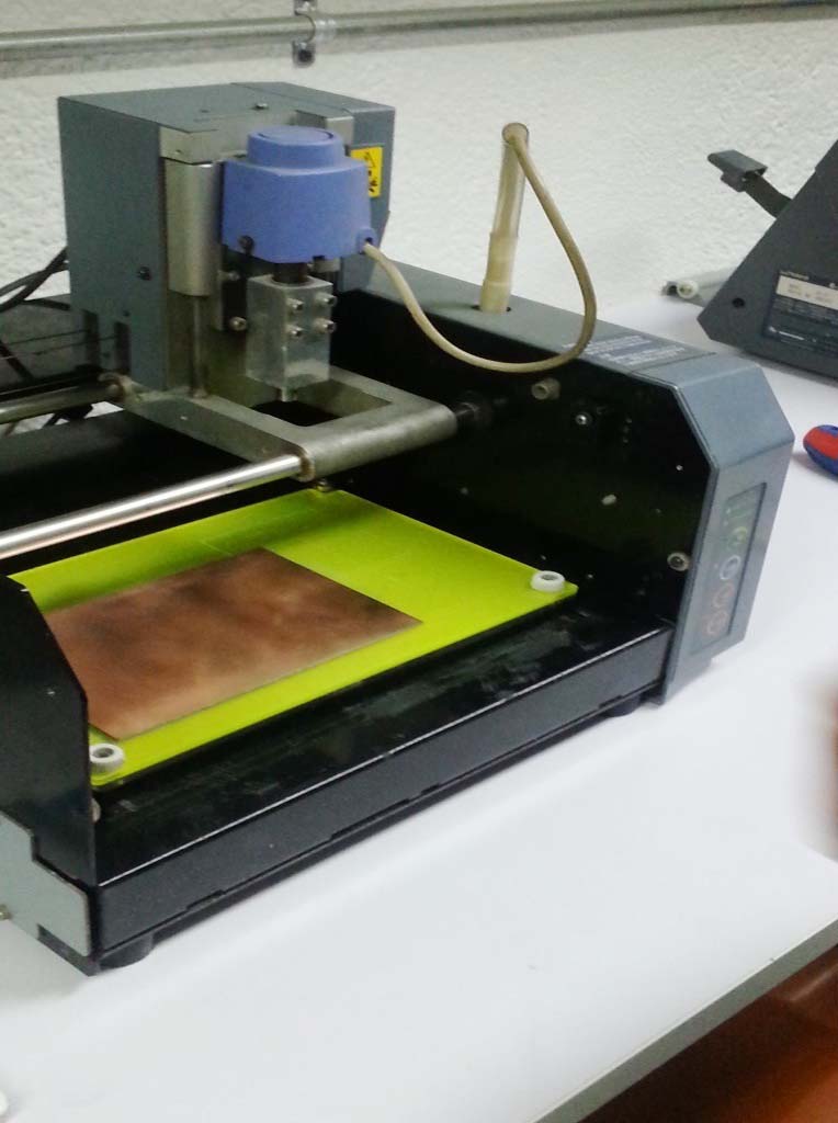
- 1 x Modela MDX-20 (More about the Machine can be found in THIS LINK
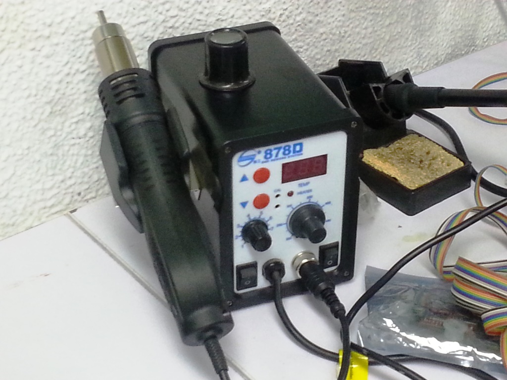
- 1 x Soldering Station.
- soldering wire
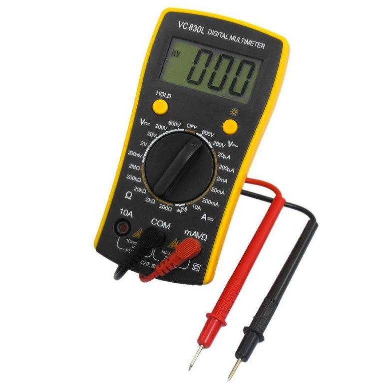
- AVO multimeter
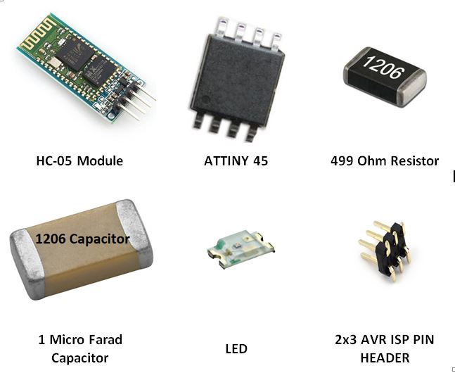
- Electronic Components (for each board, notice that we will need 2 boards. One to send and one to receive) Including:
- 1 x ATTiny45-SSU.
- 1 x (2x3) pin header for AVRISP
- 2 x Female (1x6)pinheader for Rx,Tx,VCC,GND and for the HC-05
- 1 x 1 uF Capacitor.
- 1 x LED.
- 1 x 499 Resistor.
- 1 x HC-05.

CIRCUIT DESIGN:
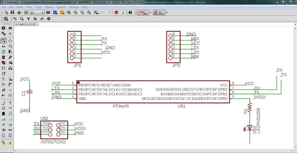
- I decided to use Autodesk Eagle as a CAD tool to design the circuit, I followed the same steps that I performed in WEEK 7 electronic design assignment.
- I opened EAGLE: I created a new project then I created a new a new schematic and I [erformed the following] :
- I added the ATTINY45, LED, 1 Micro Farad Capacitor, headers and 499 Ohm Resistor.
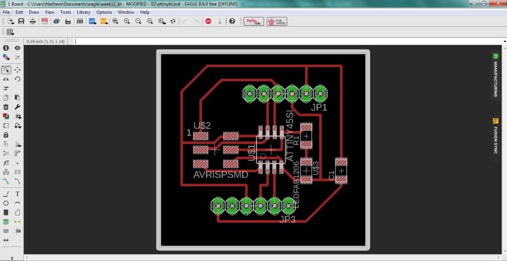
- I connected the components as shown below.
- I then switched to the board view by going to the top menu > File > switch to board. The board view will open up and components we just added will appear
- Use "move" to move each component around and "route" to route each trace. The wire will turn red as you route it into place.
- Keep moving and adjusting the wires and components till you reach the final desired layout as shown below.
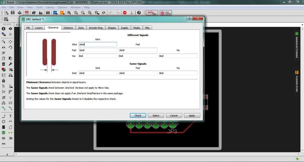
- After I finished the orientation and wiring the components in the board view I started to do the design check also known as DRC. the main purpose of te DRC is to ensure that the used 1/64 inch mill-bit tool will have enough clearance to mill around the traces and in-between them.
- a mill-bit with the diameter of 1/46 inch (~16 mil) is used; So I opened the DRC from The "Tools" menu. Then in the "Clearance" tab, I wrote "16mil" to all the fields there.
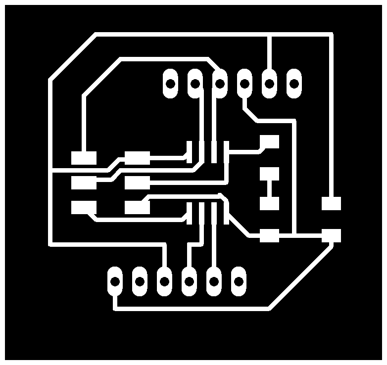
- Finally I started to export the circuit to PNG image and I edited them using GIMP to create the TRACES PNG FILE and BORDERS PNG FILE and I performed the following steps:
- I opened GIMP, I opened the file I exported from Eagle and then I used the "Rectangle Select" tool, I selected the inner border of the dimension rectangle and then right-click->Image->Crop To Selection.
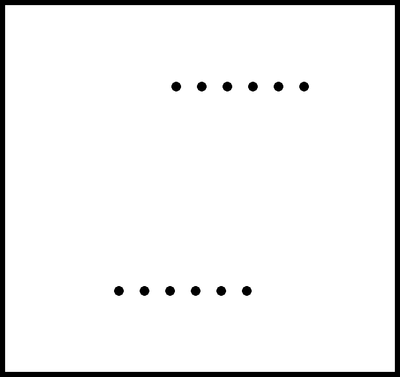
- To add a border, I clicked Image->Canvas Size and added 20px to width and height and the clicked on the "Center" button. Then to make the border white, I clicked Image->Flatten Image. Then saved the image.
- I created a new layer and I copied to it all the through-hole circles.
- In the main layer I used the "Bucket Fill Tool", I blackened all the traces so that I'm left with only a white border and I inverted the color to get white borders.
- I went back to the layer where I created through-hole circle and I colored them whith black color.
- I exported the created files as PNG, Now we are ready for milling.
CIRCUIT PRODUCTION (MILLING AND SOLDERING):
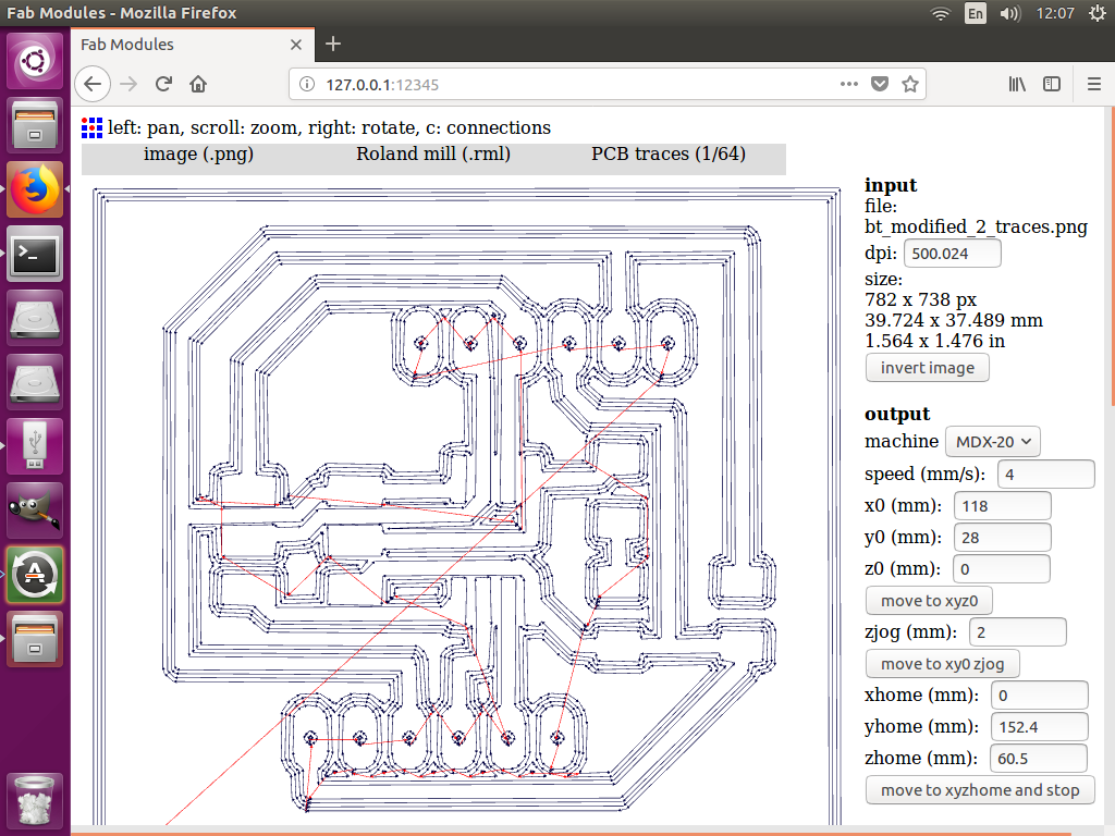
- I started milling the circuit PCB board on the Modela MDX-20 using Fabmodules and soldering the components follwoing the same principles we learned in WEEK 5
- For milling the traces:
- I used the 1/64 inch diameter end mill
- cutting depth = 0.25 mm
- number of offsets = 4
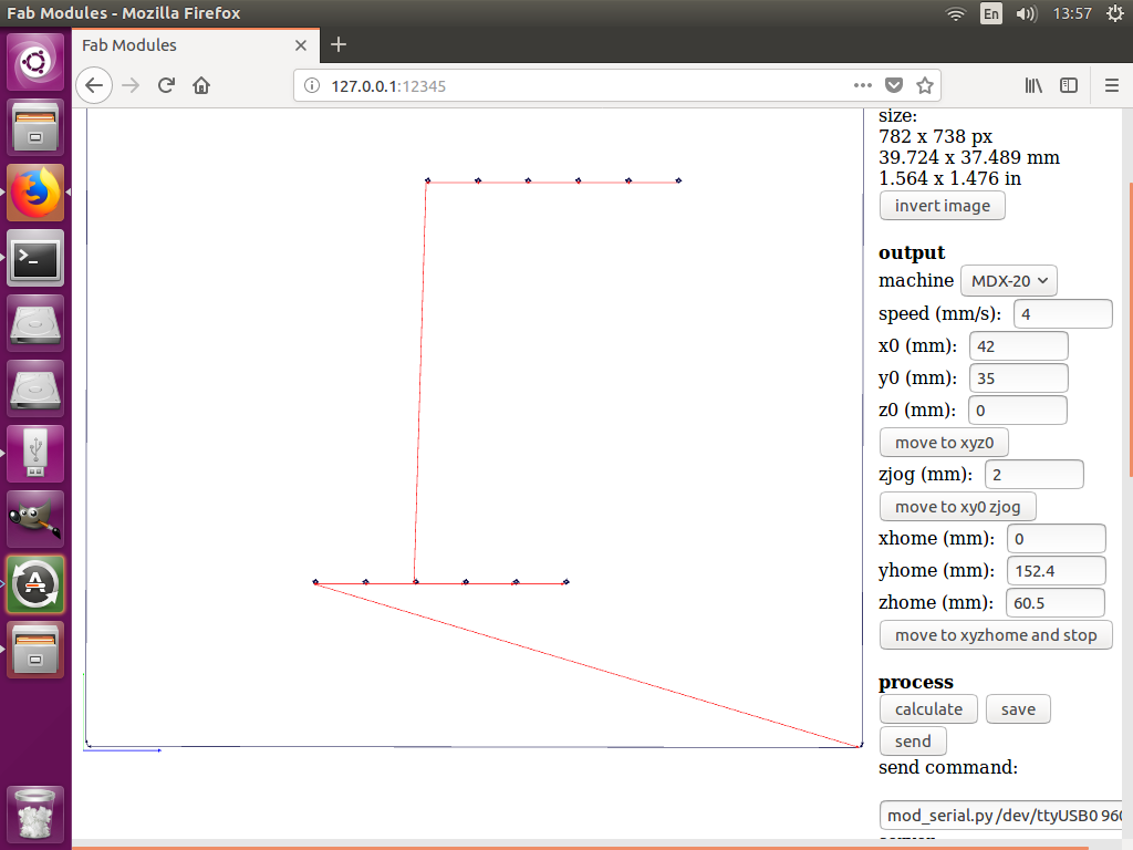
- For milling the borders:
- I used the 1/32 inch diameter end mill
- cutting depth = 0.25 mm
- cutting depth = 0.6 mm
- I then started the milling as shown in hte video below
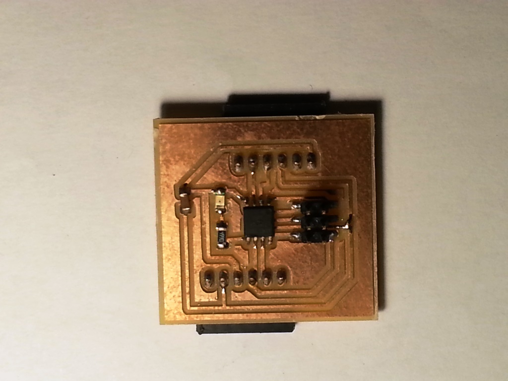
- When I created my board, I soldered the electronic components in the PCB circuit as shown below
CONFIGURING THE MASTER AND SLAVE HC-05 MODULES:
- To add the MASTER and SLAVE configuration to the HC-05 modules, you need to enter in AT command
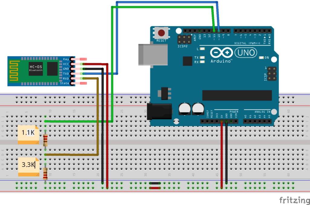
- I connected the HC-05 module to the ARDUINO UNO board as shown below.
- I performed the following steps to Enter the "AT MODE":
- Disconnect the +5v line from the modules end.
- Press and hold the small button on the bottom right of the HC-05 board (DO NOT RELEASE IT!)
- Reconnect the +5v connection
- Now Release the switch. Notice that the led on the module starts blinking once every two seconds, slower than normal disconnected mode.
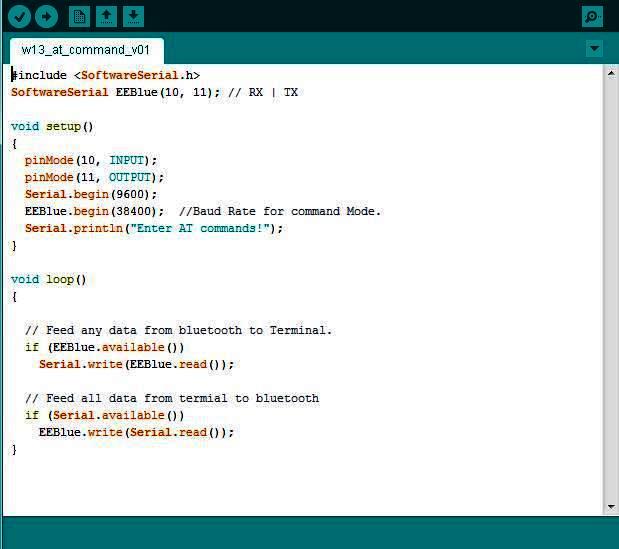
- Upload the code below to the Arduino.
TO CONFIGURE SLAVE:
- Open up the terminal hit AT and check if the module echos back OK!.
- I executed the following AT commands to change the HC-05 default configuration:
- AT+RMAAD : Clears any previously paired devices
- AT+ROLE=0 : Sets the device to slave mode.
- AT+RESET : Resets the module, required after changing the previous settings.
- After this reset, your module may revert from AT command mode, so you will need to go through the process to set it in command mode again.
- AT+CMODE=1 : Sets the CMODE to allow connection to any device.
- AT+PSWD=1234 : Sets the password to 1234 which should be set the same on the slave device
- AT+INIT: Start Serial Port Profile, it may return error(17) which just means it’s already loaded
- AT+ADDR?:we will get back the address of the Bluetooth module and it should looks something like this: 98d3:34:905d3f.
TO CONFIGURE MASTER:
- similarly, connect the master hc-05 and Open up the terminal hit AT and check if the module echos back OK!.
- I executed the following AT commands to change the HC-05 default configuration:
- AT+RMAAD : Clears any previously paired devices
- AT+ROLE=1 : Sets the device to master mode.
- AT+RESET : Resets the module, required after changing the previous settings.
- After this reset, your module may revert from AT command mode, so you will need to go through the process to set it in command mode again.
- AT+CMODE=0 : (To connect the module to the specified Bluetooth address and this Bluetooth address can be specified by the binding command).
- AT+BIND=xxxx,xx,xxxxxx : (Now, relace the XXXXXXXXX with your respective address to the slave. Note the commas instead of colons given by the slave module).
- AT+PSWD=1234 : Sets the password to 1234 which should be set the same on the slave device
- AT+INIT: Start Serial Port Profile, it may return error(17) which just means it’s already loaded

PROGRAMING AND TESTING THE MASTER AND SLAVE BOARDS:
PROGRAMMING AND TESTING USING ARDUINO
- For each of the MASTER and SLAVE: I connected the HC-05 to the Arduino as shown in the fiagram below and I uploaded the code below (same Code I used for the AT mode configuration)
- I connected each Arduino to a different laptop and I opened serial monitor in the ardiono IDE in each of them.
- Both the MASTER and SLAVE HC-05 boards LEDs started to blink rapidly then once they got paired the blinking started to be slower (almost 2 blinks 1 sec apart).
- I typed a digit in Serial monitor input in the laptop connected to the MASTER board -> The digit appears in the Serial monitor in the laptop connected to the SLAVE board.
- I typed a digit in Serial monitor input in the laptop connected to the SLAVE board -> The digit appears in the Serial monitor in the laptop connected to the MASTER board.
- This can be shown in the video below.
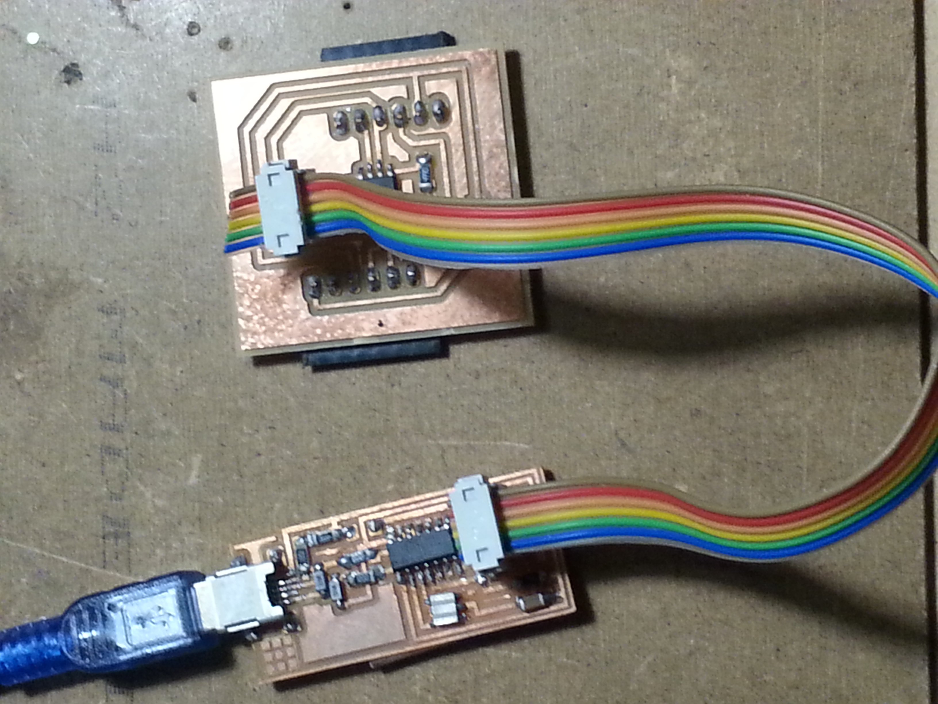
PROGRAMMING AND TESTING USING MY BLUETOOTH BOARDS WITH ARDUINO IDE AND FABISP AS A PROGRAMMER
- Connect the FAB ISP pins to my board pins with each pin connected to its corresponding similar pin as follows:
- MISO (in FAB ISP) -> MISO (in Bluetooth Board)
- MOSI (in FAB ISP) -> MOSI (in Bluetooth Board)
- SCK (in FAB ISP) -> SCK (in Bluetooth Board)
- Vcc (in FAB ISP) -> Vcc (in Bluetooth Board)
- GND (in FAB ISP) -> GND (in Bluetooth Board)
- RST (in FAB ISP) -> RST (in Bluetooth Board)
- Connect the FAB ISP to the usb Port and ensure it is detected by the PC.
- Connect the FTDI Cable to the FTDI header in the FTDI pins in the Bluetooth Board.
- open arduino IDE then burn the BOOTLOADER.
- To burn the BOOTLOADER I followed the following steps:
- Select "USBTinyISP" under Tools > Programmer.
- Select ATtiny from Tools > Board.
- Select the specific ATtiny you are using (44/45/84/85) from Tools > Processor.
- Next select "16 MHz (INTERNAL)" from Tools > Clock.
- select "Burn Bootloader" under tools and wait till it complete.
- I looked at the ATTINY45 Datasheet and the PINOUT map in the diagram below to identify the ARDUINO mapping of the Attiny45 pins
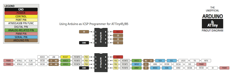
- I assigned in each of the 2 boards the PINS as follows:
- Bluetooth RX -> PIN 1 (Physical ATTINY45 PIN 6) and Bluetooth TX -> PIN 2 (Physical ATTINY45 PIN 7)
- ATTINY45 LOCAL RX -> PIN 3 (Physical ATTINY45 PIN 2) and Bluetooth TX -> PIN 4 (Physical ATTINY45 PIN 3)
- LED PIN -> PIN 0 (PHysical ATTINY45 PIN 5)
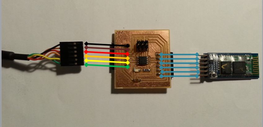
- I connected each of the 2 boards to FTDI cable and HC-05 module as shown in the connection diagram below.
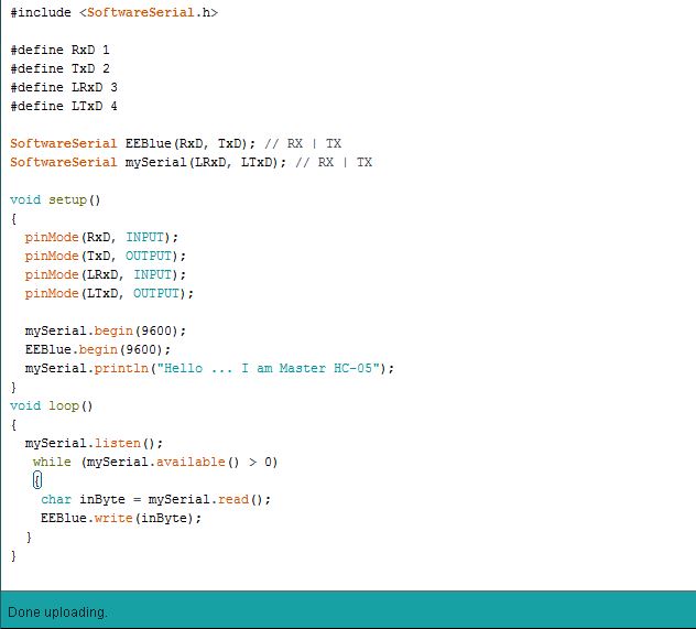
- I wrote the following code for the MASTER and below are few notes about the code:
- I initiated the code and I made the board write to the ATTINY Software Serial a sentenc to declare that this is the MASTER module.
- I programmed the board to listen to any input coming from the ATTINY Serial and Once a character is received to direct it / Write to the Bluetooth Software Serial (AKA in this code as EEBlue).
- I initiated the code and I made the board write to the ATTINY Software Serial a sentenc to declare that this is the SLAVE module.
- I programmed the board to listen to any input coming from the HC-05 Serial and Once a character is received, it checks the character value:
- If Value = 1 -> It print "1 Received" to acknowledge it received 1 and it Turn ON the LED
- If Value = 0 -> It print "0 Received" to acknowledge it received 0 and it Turn OFF the LED
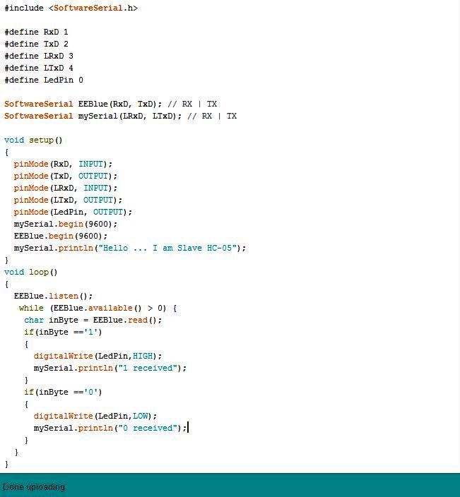
- I compiled the code then I uploaded it.
Files: