WEEK 3 - COMPUTER-AIDED DESIGN
INTRODUCTION
This week I decided to use Autodesk Fusion 360 as the main tool to accomplish the assignment deliverables for the following reasons: It can perform all the needed functionalities (i.e: 2D, 3D, animation,etc), I did not work with it before so it provides opportunity to learn new tool and finally because its convenience as it works over the cloud. To experience and evaluate more than one software I used 2 approaches:
- Approach A: Creating 2D design using inkscape and then built the 3d using Fusion (but this was not parametric and painful).
- Approach B: Creating 2D and 3D design using Autodesk fusion 360 (parametric design and it is preferred approach)
Assignment Description
- Model (draw, render, animate, simulate, ...) a possible final project.
- Post it on your class page with original 2D and 3D files.
Learning Outcomes
- Evaluate and select 2D and 3D software.
- Demonstrate and describe processes used in modeling with 2D and 3D software.
Have you (Checklist)
- ✔ Modeled experimental objects/part of a possible project in 2D and 3D software?
- ✔ Shown how you did it with words/images/screenshots?
- ✔ Included your original design files?
STEPS PERFORMED:
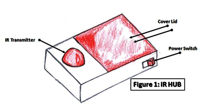
- I wanted to create an enclosure for my IR transmitter, so I used the earlier created 3D drawing for my proposed project as a reference.
- Now it was important to choose the material before starting to draw as it will affect the joints I will use. I decided to use mainly plywood with 3 mm thickness as it is cheap, easy to use and assemble.
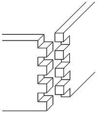
- I also read a little about wood joints and after going through this useful tutorial https://en.wikipedia.org/wiki/Woodworking_joints I decided to use finger joints. Now it is time to draw.
Approach A: (Inkscape for 2D – Fusion 360 for 3D, Rendering and Animation)
- Download inscape from This Link and Install it.
- I went through This Tutorial to learn how to create finger joints 2D drawing using inkscape.
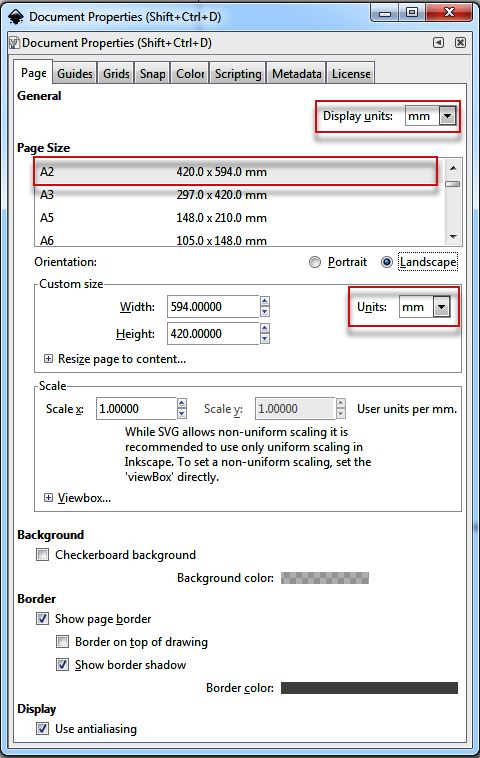
- Open Inkscape, go to “document properties” under the file menu and set your dimensions to millimeter and chose the page size (I chose A2, Landscape)
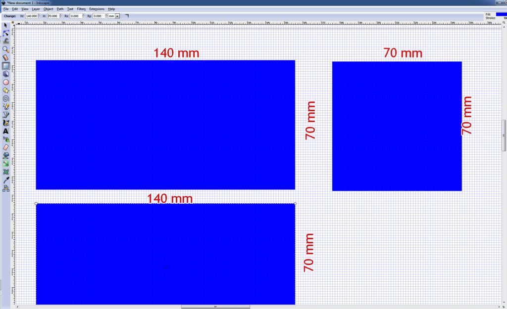
- Assuming the enclosure dimensions are: width 70 mm x Length 140 mm x Height 70 mm (The enclosure size is not firmly set yet as it will depend on the later size of the electronic PCB to be put inside it).
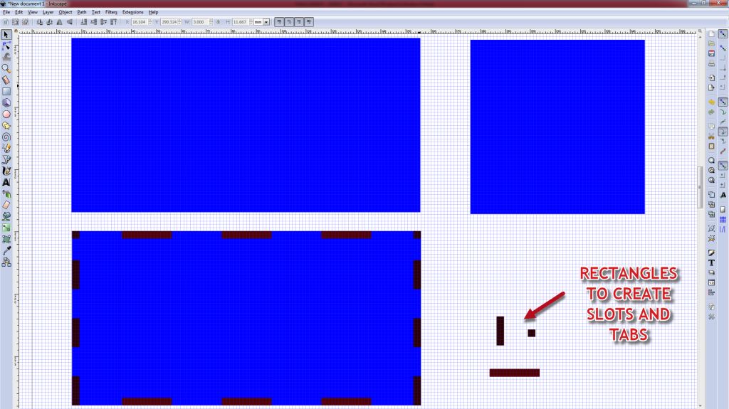
- Create 3 rectangles with the following dimensions (70 mm x 70mm), (140 mm x 70mm) and (140mm x 70mm).
- Create 3 small rectangles to create the slots (tabs) with the following dimensions: (Length / 7 slots x Thickness = 20mm x 3mm), (width / 5 slots x Thickness = 14mm x 3mm), (Thickness x Thickness = 3mm x 3mm) and finally (height / 6 x thickness = 11.667 mm x 3mm).
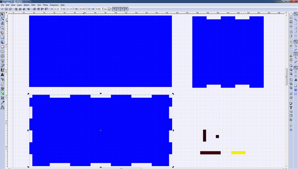
- Clone (Remember clone not copy!) the rectangles we created for the slots and place them as shown below on the enclosure faces.
- Select the slot rectangle and the enclosure face rectangle go to the path menu and select difference to cut out the slots from the face rectangle.
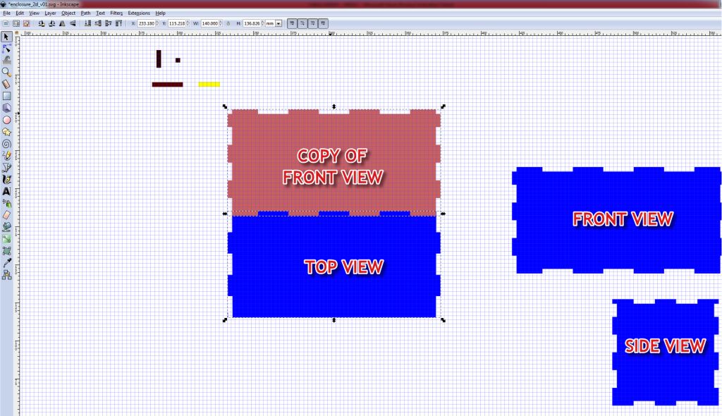
- Similarly copy the side view face and the front view face and place them on the top view face then select “PATH MENU” and “DIFFERENCE”.
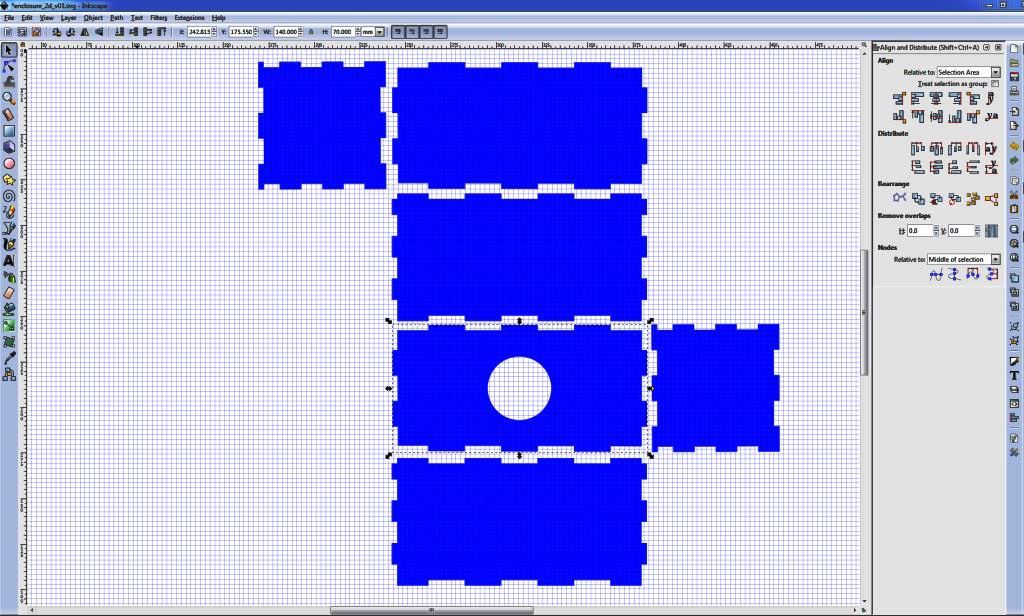
- Now duplicate the needed enclosure faces to ensure that all the faces are represented in the 2D drawing
- Save the drawing as DXF file. (Notice that I tried to save it as SVG but the edges and the circles were not showing up correctly when I imported them to Fusion 360)
- If you are like me and have no experience using Autodesk Fusion 360, then go through This Tutorial
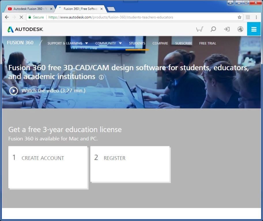
- Go to This Link , create account, register then download and Install it.
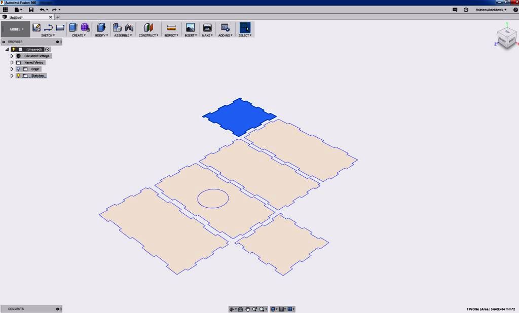
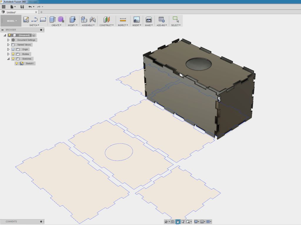
- Open Autodesk fusion 360 and create a new project, then go to insert menu on the top bar and insert the DXF file we exported from Inkscape, then select each face in the imported DXF and extrude it as a separate body.

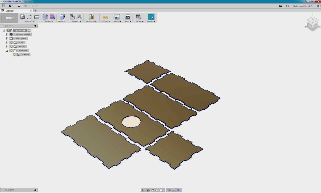
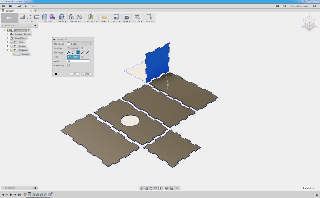
- Start folding the sides to form the enclosure shape by using the MOVE tool in a free form mode.
- Although this will work but still I did not go with this approach as it had the following disadvantages:
- It does not introduce parametric design.
- Each time I needed to do modifications I had to go back to Inkscape and then modify the 2D and export to do the whole process again!!!
Approach B: (Fusion 360 for 2D, 3D, Rendering and Animation):
- If you jumped directly to this step then please Go to This Link , create account, register then download and Install it.
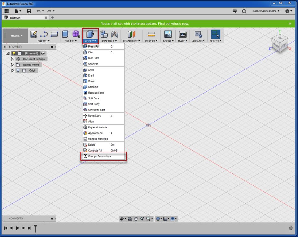
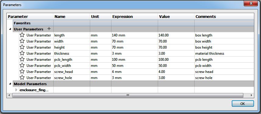
- Start a new project, set your parameters to ensure that your design is parametric, Under the MODIFY section in the top ribbon, click on Sigma and set your parameters. I did set length, width, height, thickness, PCB length, PCB width, screw hole diameter and screw head diameter as below.
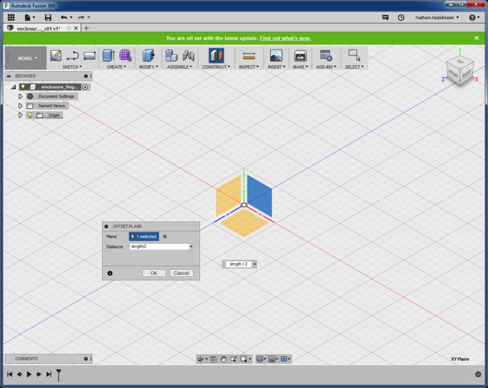
- Under construct Menu, set offset plane and then make the offset length /2. Now sketch a square on that plan with dimensions (Width x Height = 70mm x 70mm).

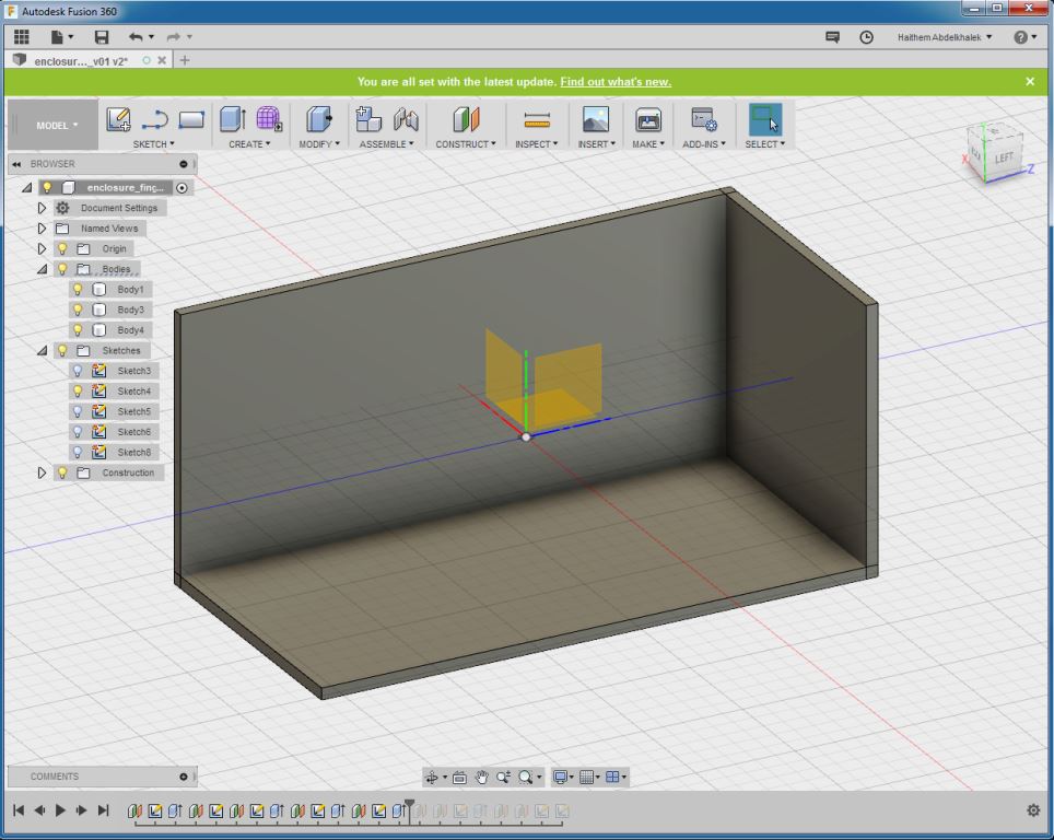
- Similarly, create offset planes and then make the offset width /2 and –Height / 2. Now sketch rectangles on the planes with dimensions (Width x length = 70mm x 140mm) and (height x length = 70mm x 140mm)
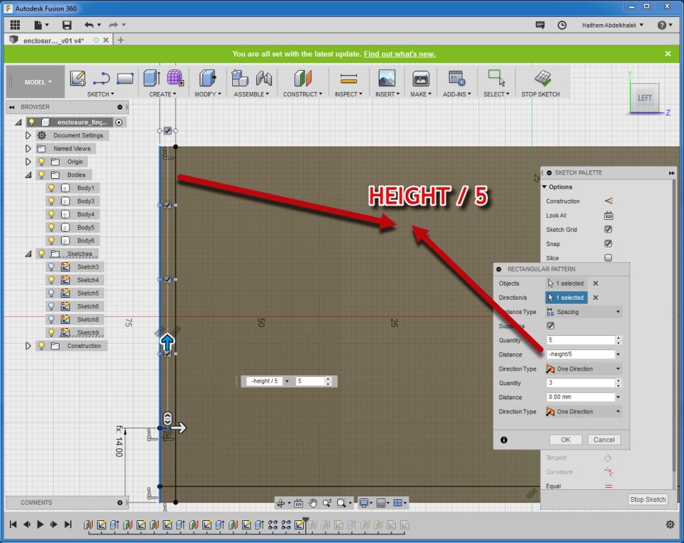
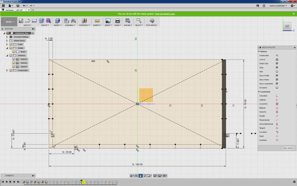
- Select the front view face and start sketching, draw lines to represent the thickness.
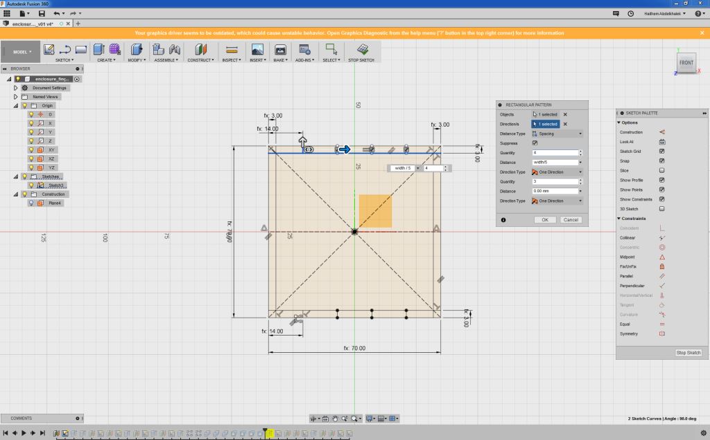
- Draw horizontal line and create a rectangular pattern for the lines so they look as below.
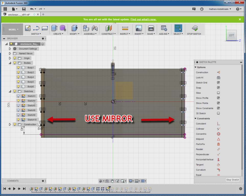
- Mirror the created lines so they appear on the other side.
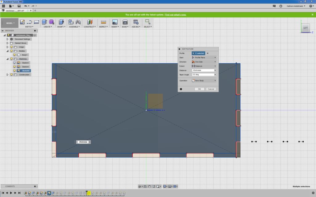
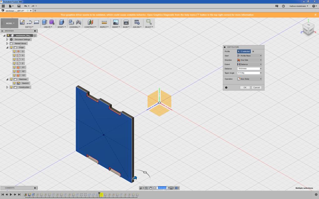
- Extrude with (-Thickness) to create all the needed slots.
- Repeat the same previous steps to create the slots for all the enclosure faces / bodies
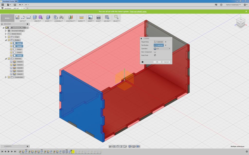
- Then from the top bar, select MODIFY then select combine so the extruded tabs cut through the slots
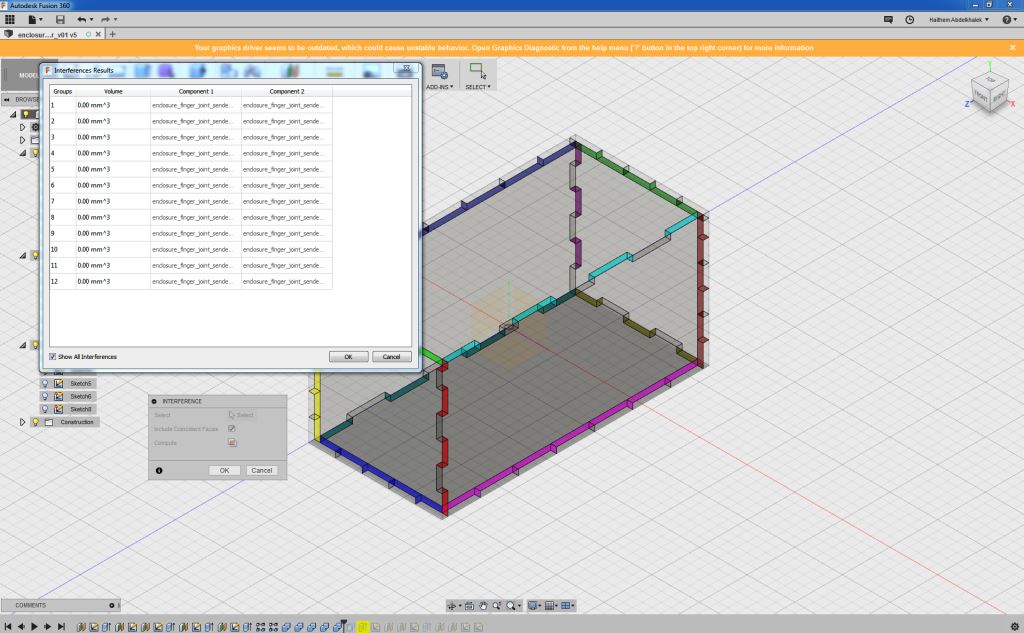
- Now check for interference by going to INSPECT menu and selecting Interference then select the bodies to inspect.
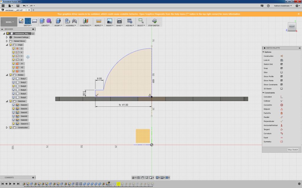
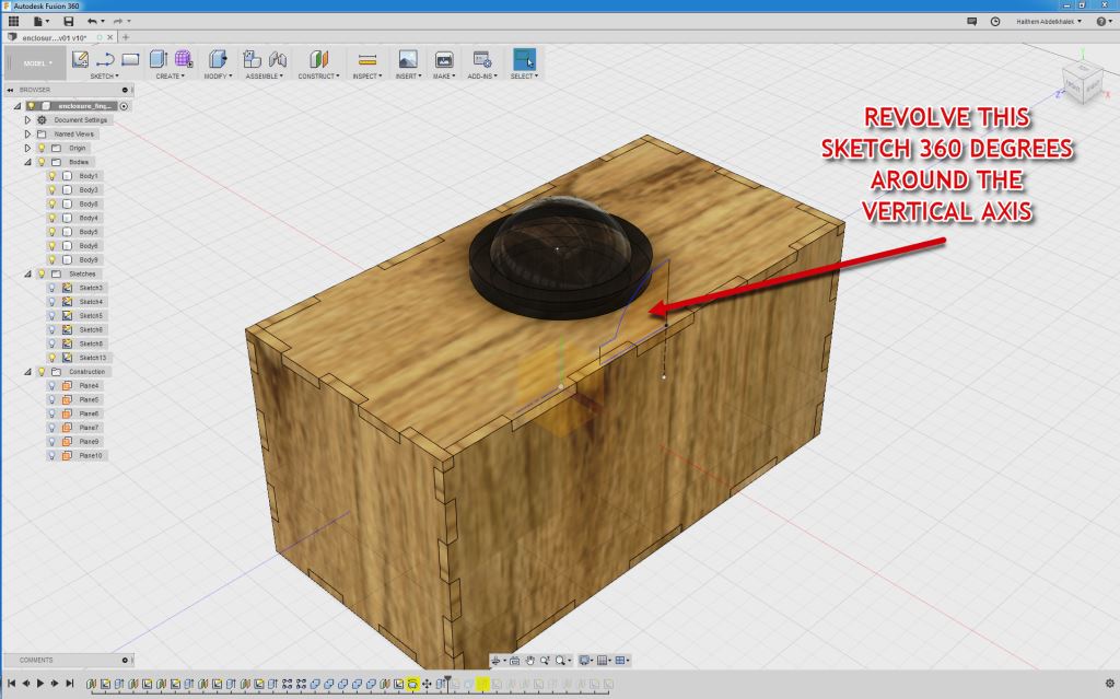
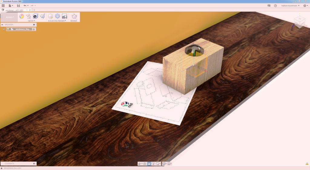
- Now to create the dome, draw a sketch as shown below and then revolve it.
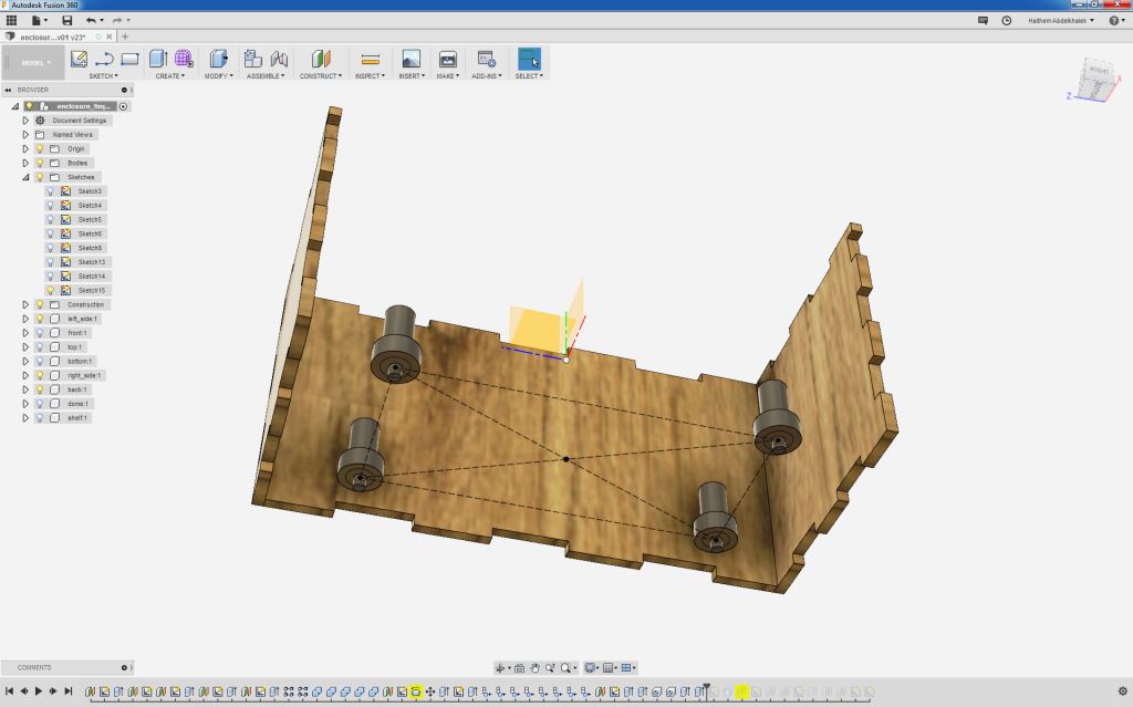
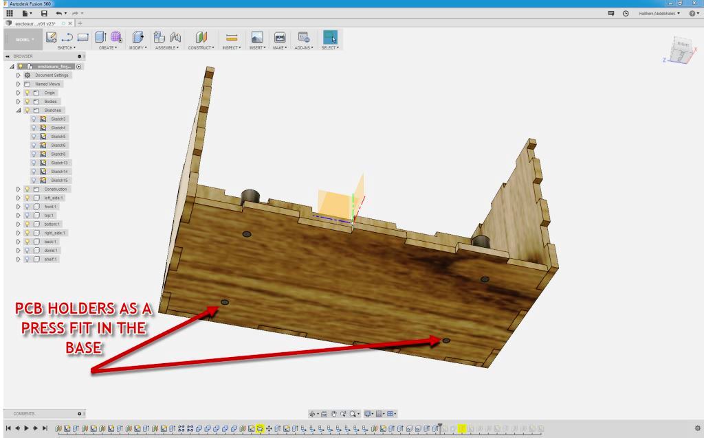
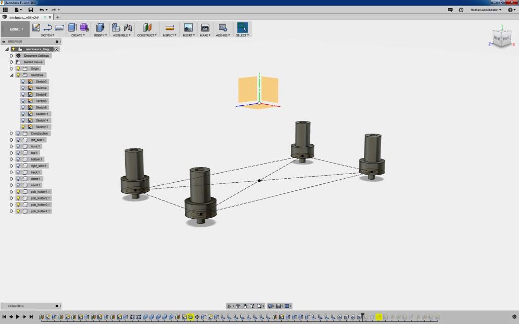
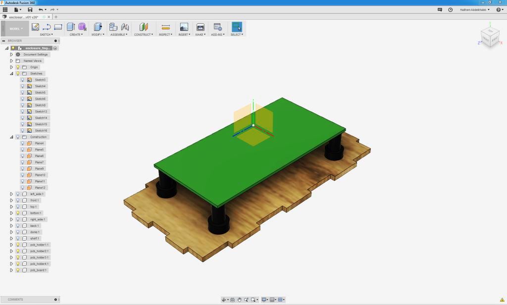
- I created a PCB body and PCB holders that are fixed on the base surface by press fit as below.
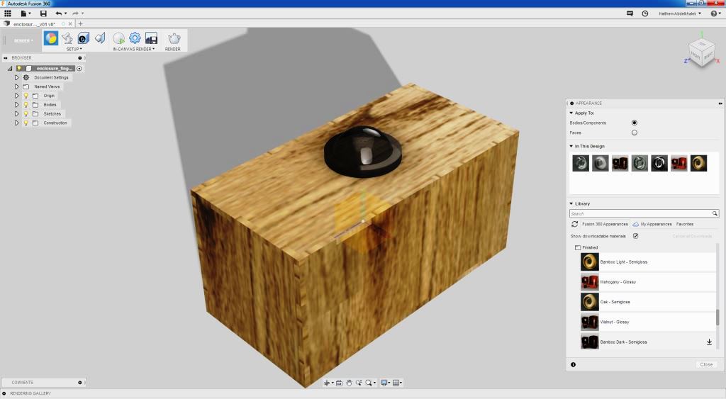
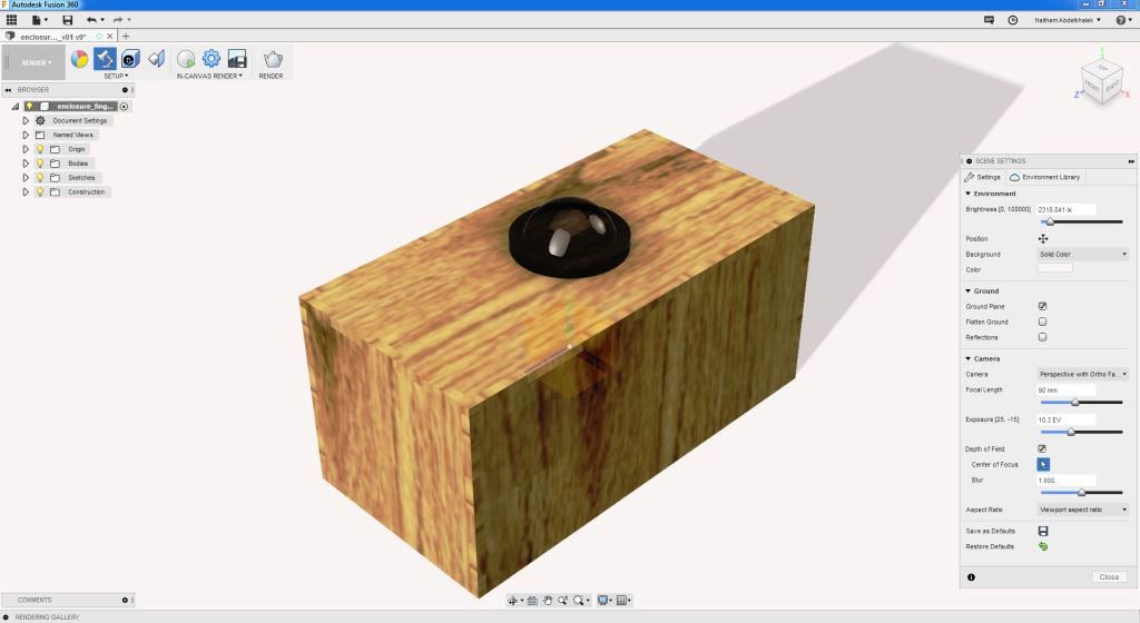
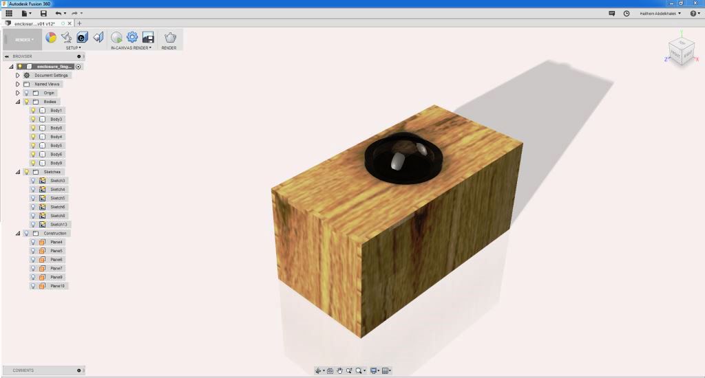
Rendering:
- Now go to rendering menu and select appearance to change the appearance for the bodies (I chose wood) for the enclosures and glass for the dome. Then I adjusted the scene settings..
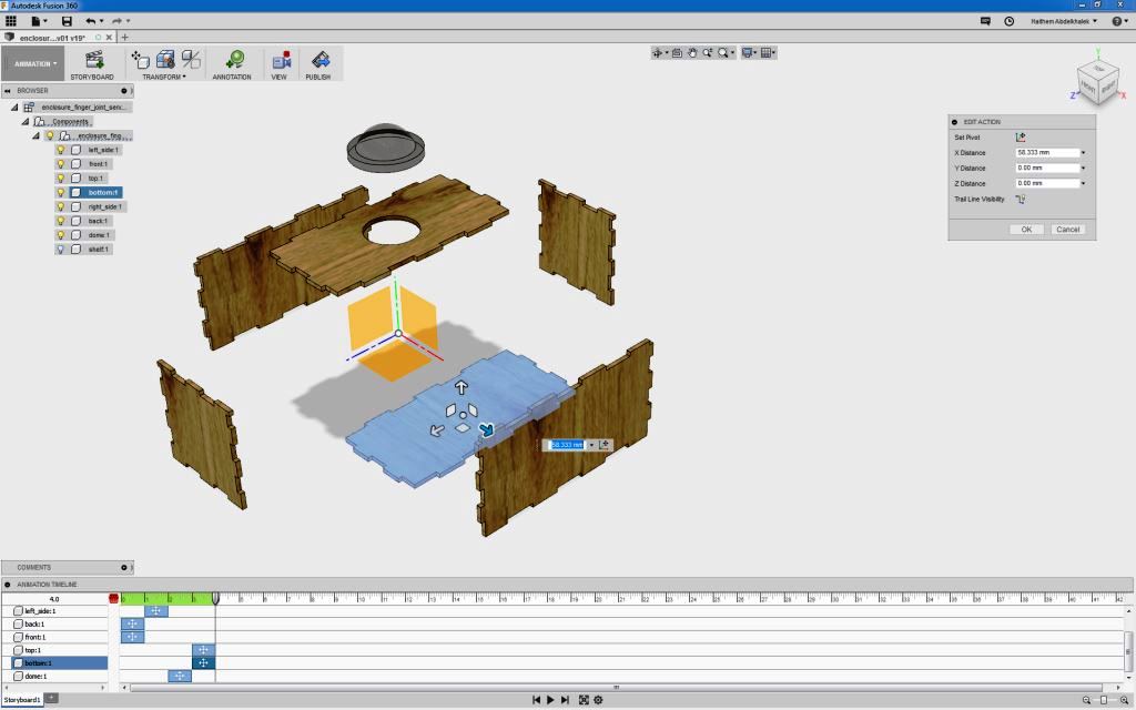
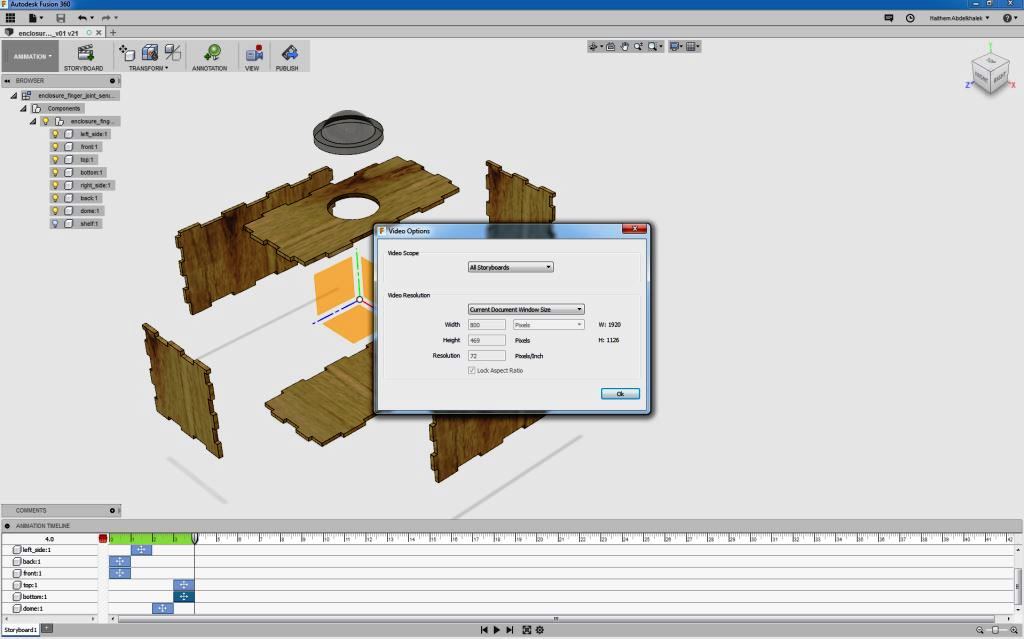
Animation:
- Finally I am creating the animation by going to the animation menu and make a manual explode to show all parts then export the animation as video file.
Files: