WEEK 5 - ELECTRONICS PRODUCTION
INTRODUCTION
This week was all about the electronics production, although It was not my first time to create a PCB but it was the first time to do a surface mount soldering rather than through-hole. I was also really nervous becasue I heard that dealing with the modela is quite hard.
Assignment Description
- Characterize the specifications of your PCB production process?
- Make an in-circuit programmer by milling the PCB?
- Optionally, trying other processes?
Learning Outcomes
- Describe the process of milling, stuffing.
- Demonstrate correct workflows and identify areas for improvement if required.
Have you (Checklist)
- ✔ Shown how you made the board.
- ✔ Explained any problems and how you fixed them.
- ✔ Included a ‘hero shot’ of your board.
TOOLS AND HARDWARE USED (BOM):
- 1 x FR1 (Copper PCB Board).
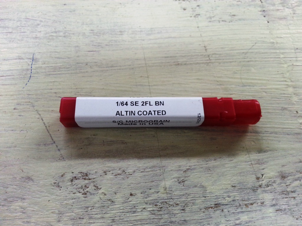
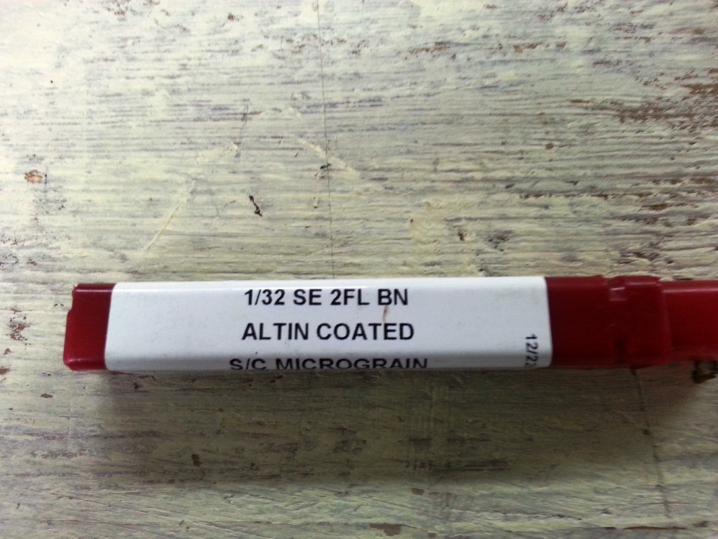
- 1 x 1/64 inch end mill bit.
- 1 x 1/32 inch end mill bit.
- 1 x double tape.
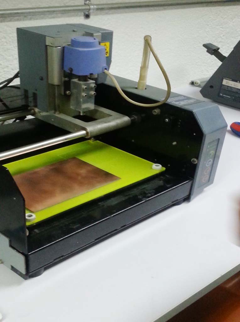
- 1 x Modela MDX-20 (More about the Machine can be found in THIS LINK
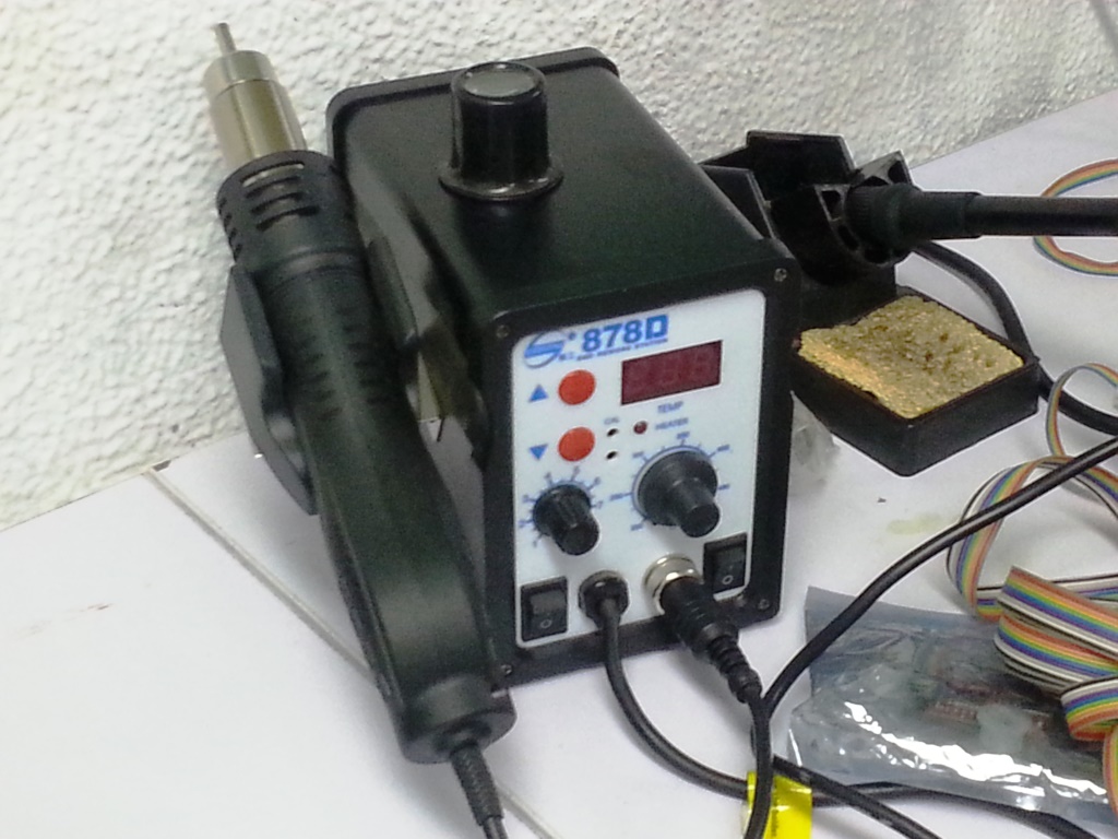
- 1 x Soldering Station.
- soldering wire
- AVO multimeter
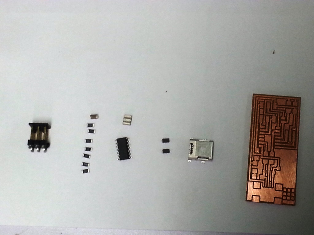
- Electronic Components Including: Resistors (1 x 10K Ohm, 2 x 1K Ohm, 2 x 100 Ohm. 1 x 0 Ohm, 1 x 499 Ohm, Capacitor, Resonator, USB Connector, ATiny44 microcontroller and male 2x3 pin header.

STEPS PERFORMED:
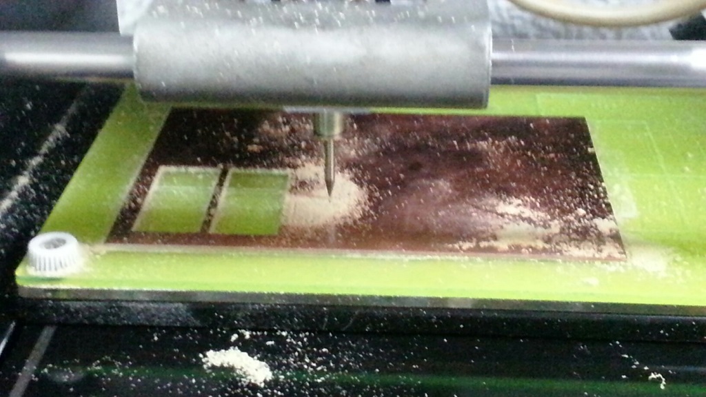
- Use the double sided tape to fix the piece of copper on the machine bed as shown below:
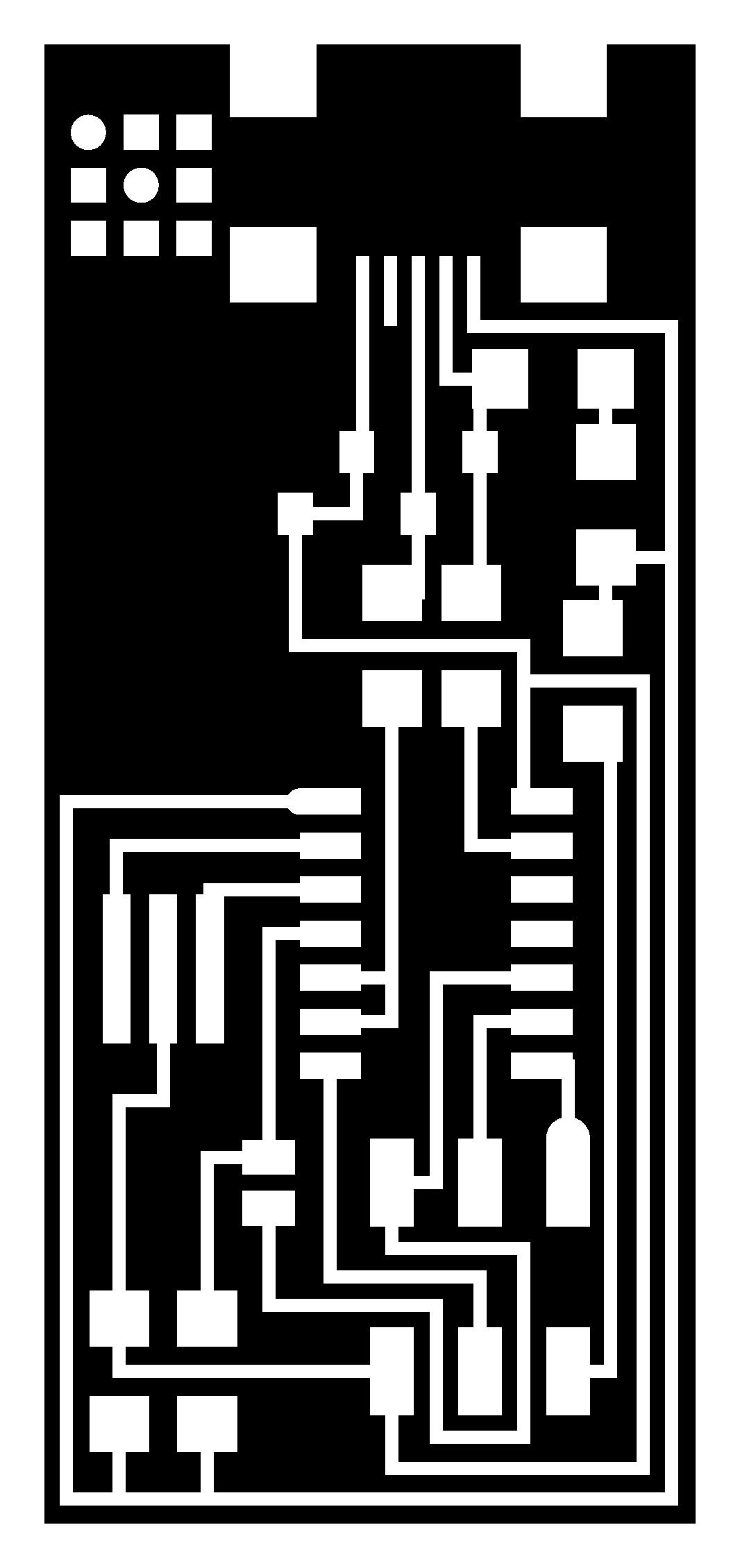
- I downloaded the circuit traces and frame PNG files for this assignment located in THIS LINK and THIS LINK as PNG files. We chose the one with the resonator as it eliminates the need for 2 capacitors and because the components used are the components we have in FAB LAB Egypt.
- The chosen board traces and frames PNG files are as shown below:


- Now we need to convert the PNG files to RML files (The RML files are the machine file format that is used by the Modela). To do that we will need to use the Fab Modules.
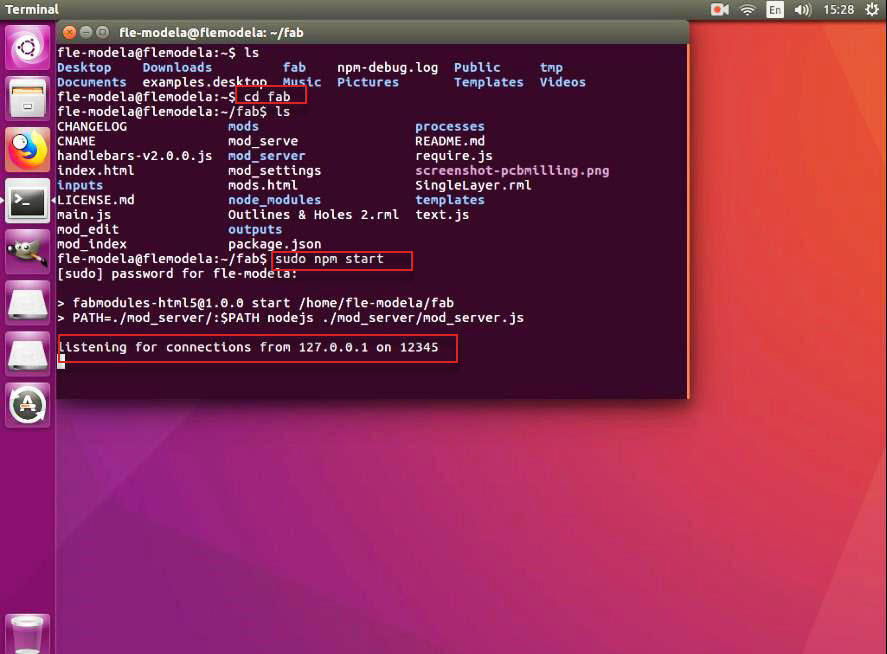
- We have the Fab Modules installed on a PC with Linux OS in Fab Lab Egypt with. To open the Fab Modules follow the following steps:
- Open a terminal, then go to the directory named “fab”.
- Type sudo npm start and then press ENTER
- I copied the PNG files downloaded for the traces and frame to the PC.
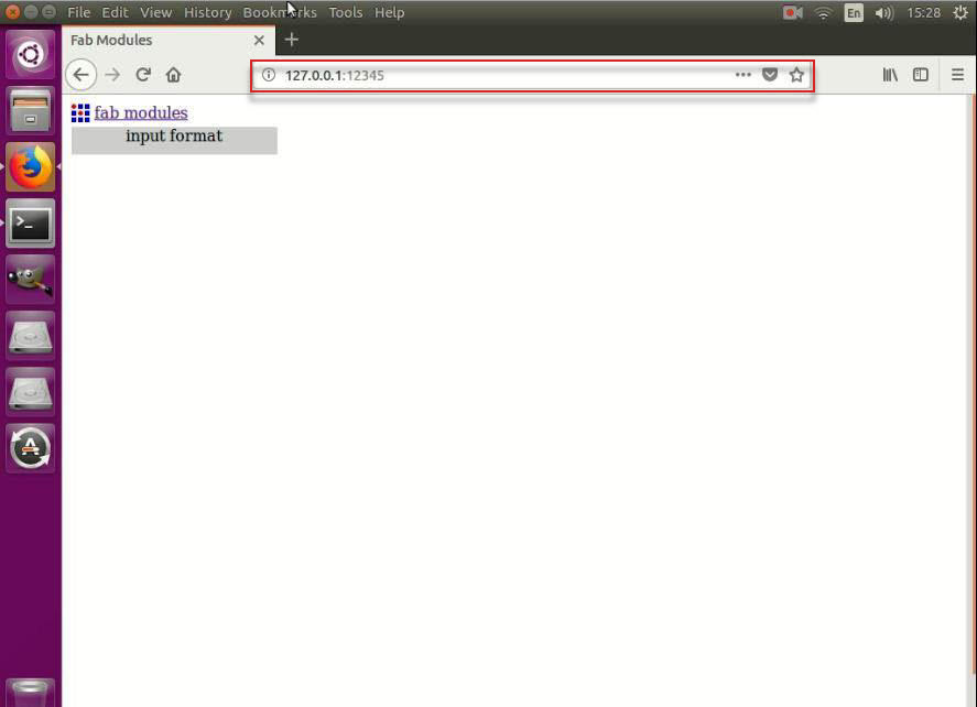
- Open the browser and browse to the URL “127.0.0.1:12345”
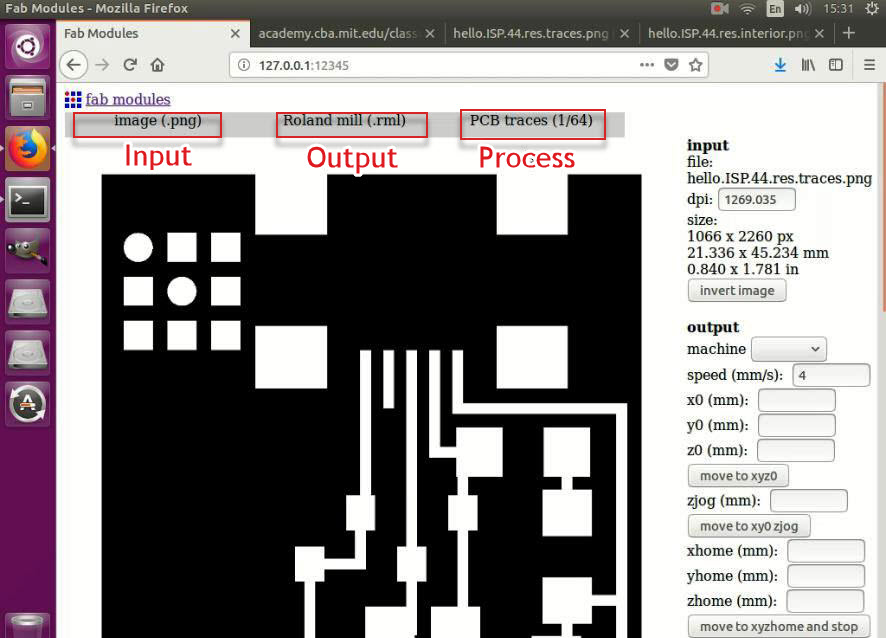
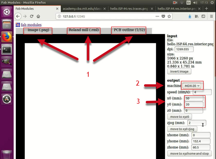
- Select the following in the top bar:
- For Input: Select image (.png) and browse to locate the traces PNG file.
- For Output: Select Roland mill (.rml).
- For Process: Select PCB Traces (1/64).
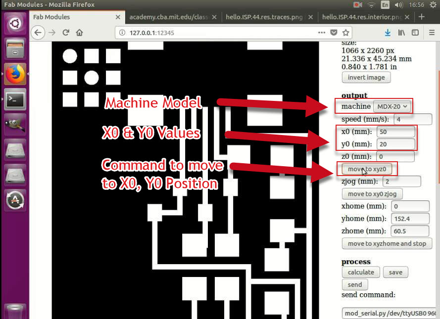
- Select the Machine type / model form the drop down menu, in my case it was MDX-20.
- Switch Off the Modela to ensure that any previous Z0 location is cleared then switch it on again.
- Enter values for X0 and Y0 for your home location, in my case it was X0=50 and Y0=20 then click move to XYZ0.
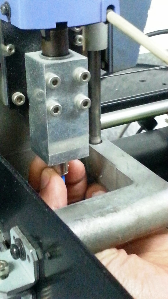
- Zero your Z axis, and this is by:
- Move your machine to the bottom carefully using the down button arrows in the side panel in the machine.
- When you are close to the copper sheet (around 0.5 mm), loosen the mill bit and allow it to slip slowly till it touches the surface of the copper.
- Re-secure the mill bit again.

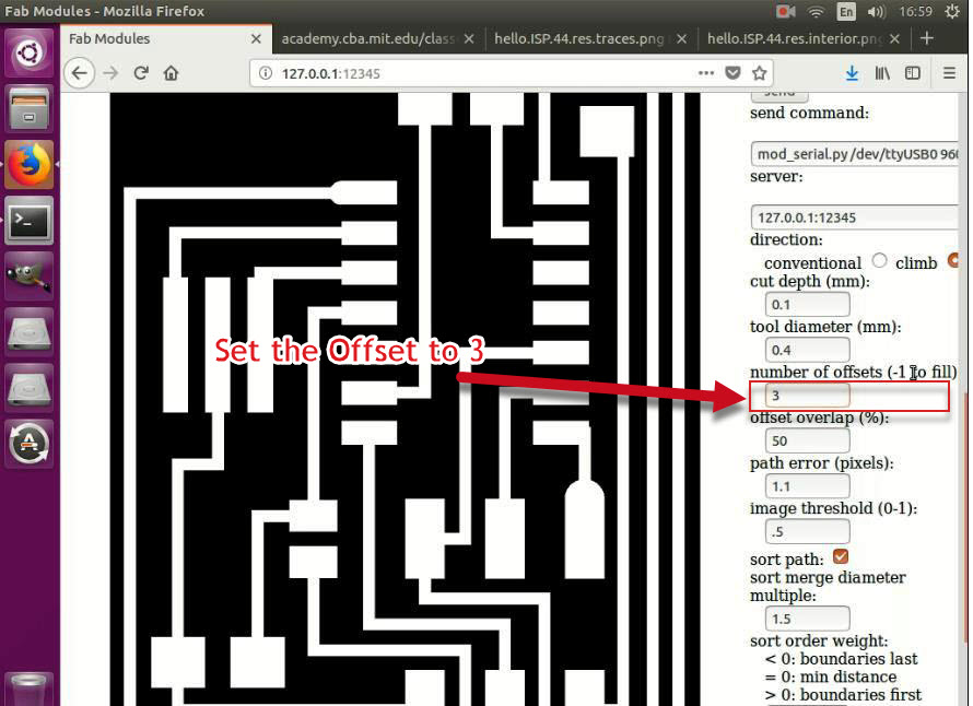
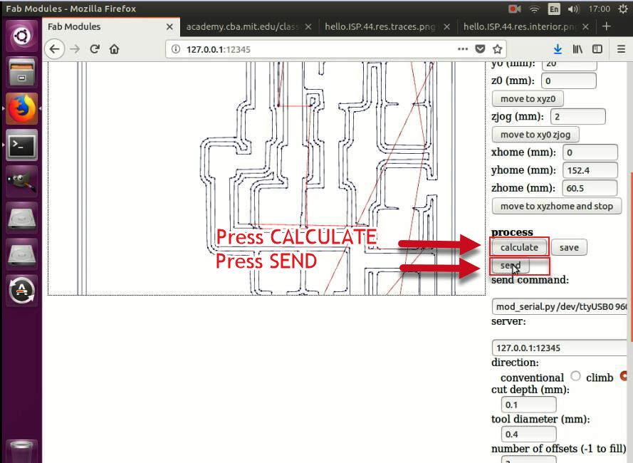
- Set the offset to the value you need (in my case I did set it to 3) then press on the CALCULATE button and examine the drawn tool paths.
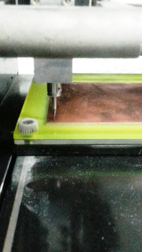
- Now click SEND button and keep your hand on the VIEW button in the machine side panel to stop the job in case you faced any issues!
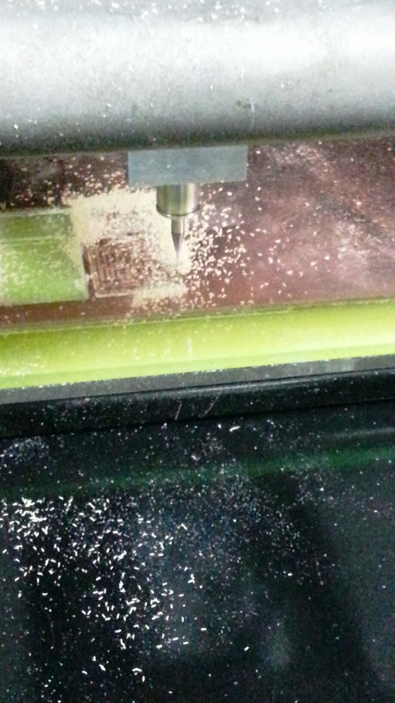
- Watch carefully till the job is finished, click on the VIEW button so the table move outside and you can see the results of the traces milling.
- Now switch off the machine, dismount the end mill by loosening the screw and remove the 1/64 inch mill bit and then mount 1/32 inch mill bit carefully in the collet.
- Open the Fab modules and do the following steps:
- For Input: Select image (.png) and browse to locate the frame PNG file.
- For Output: Select Roland mill (.rml).
- For Process: Select PCB Outline (1/32).
- Similar to the previous steps (in Milling the traces), Select the machine model and set the X0 = 50, Y0 = 20 and offset to 3. Then press on the CALCULATE Button.
- Switch on the modela move to xyz0 and move down the end mill till it touches the PCB and slightly drill.
- On Fab Modules, click the SEND button.
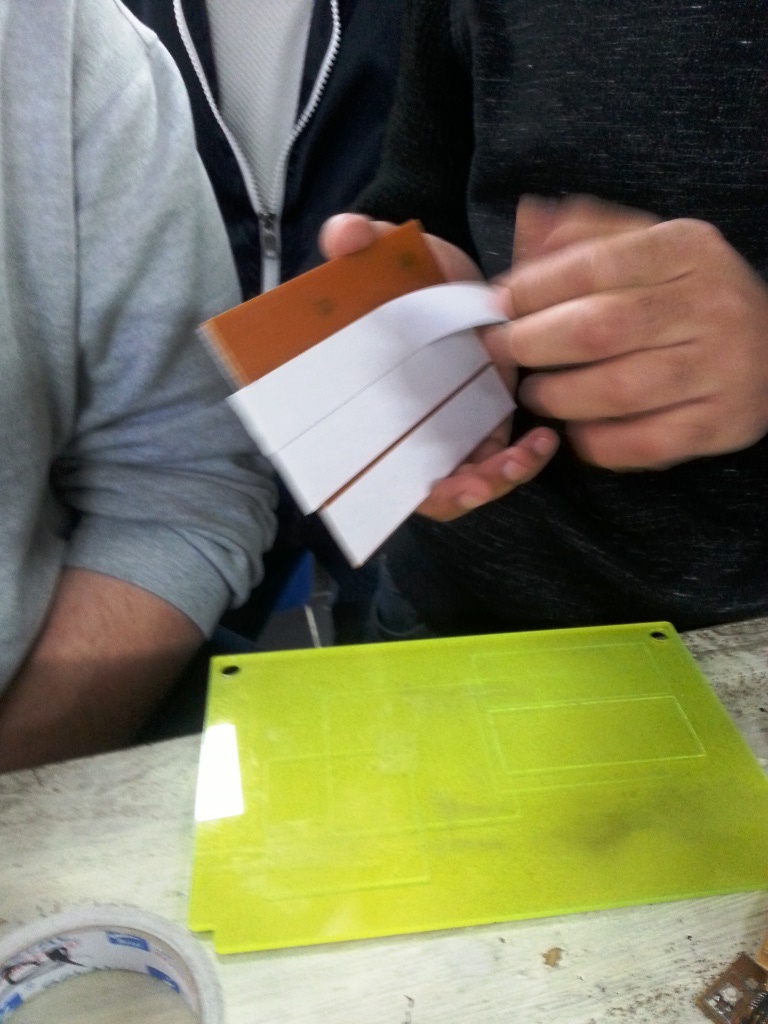
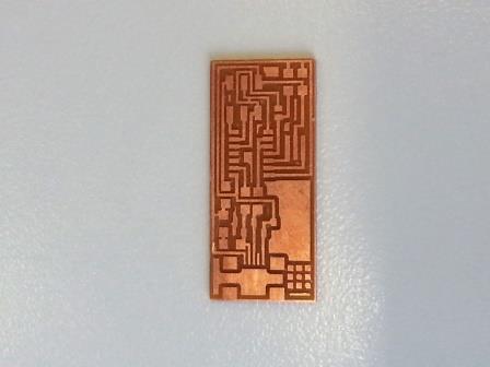
- Once the job is finished, try to remove gently the board. The result is satisfactory as shown below.
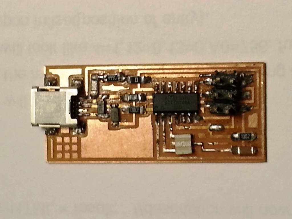
SOLDERING:
- I started soldering using the soldering station, I started with the microcontroller followed by the USB connector
Tips From Regional Review! - It is recommended to start soldering the core componenets or hardest to solder one so that if the componenets failed or the circuit was messed up you know the as early as possible that you will need to work on antoher PCB, this is an agile concept called FAIL FAST.
- For the resonator, I did put paste on the pads and then with the hot gun I heated it then I put the resonator on the melted paste while heating gently and uniformly.
- For the excess solder, I used the braid where I put the braid on the excess solder paste firmly and put the tip of the solder iron on the braid till it diffuse to the braid.
- After every soldered componenet I tested for short circuit existence using the AVO meter
- Finally I finished and it was done and below how my final circuit looked like.
PROGRAMMING FABISP:
- After being done with soldering, I followed I went through THIS TUTORIAL to know how to program my FABISP. I managed to get another FabISP as a programmer to program my FabISP
- First of All, I prepared teh following:
- Download WINAVR from THIS LINK and install it.
- Download Adafruit USBTinyISP Drivers from THIS LINK and install it.
- Download FabISP Frimware from THIS LINK .
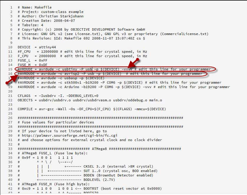
- I opened the MAKEFILE with BRACKETS (The Editor) and I edited it the file to perform the following changes:
- I uncommented the line with USBTINY and commented the AVRISP2 line [ Because I was using another FABISP].
- I added -vvvv at the end of the USBTINY line to ensure to enable the verbose file and ensure that I will get more details when I run the commands for easier troubleshooting.
- I saved the Makefile.
- Extract the firmware zip file to a folder.
- In Windows OS: Open command prompt, go to the folder where you extracted your firmware XIP file and execute the following commands:
- make Clean
- make hex
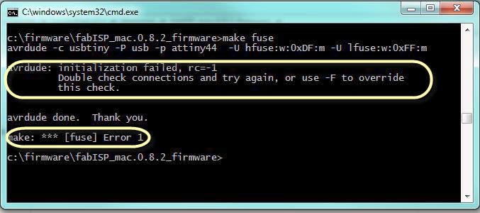
- make fuse
- make program
- In the first time I did the commands I used to get error as shown below after running the make fuse command, this was rectified once I created another PCB and it appeared that the original board had a problem.
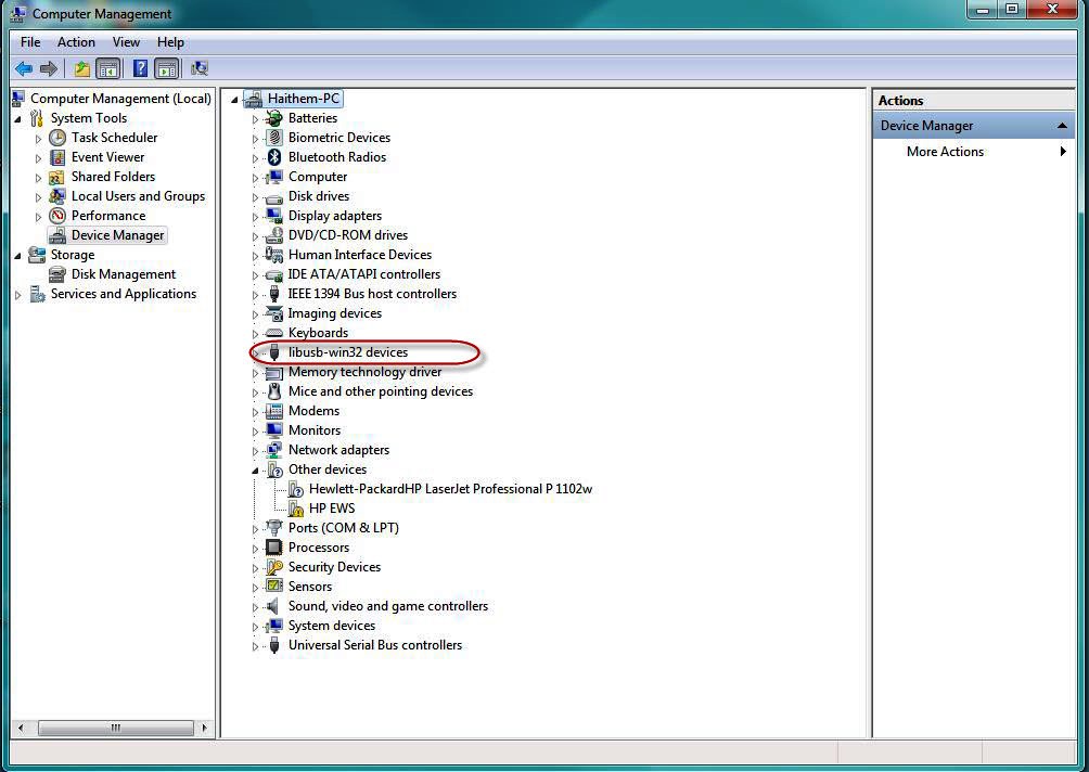
- Finally remove the zero resistance and remove the soldered short-circuit. Connect the FABISP to the USB port in your computer and ensure it is detected and appears in the device manager as USBTINY as shown below.
Files: