WEEK 9 - EMBEDDED PROGRAMMING
INTRODUCTION
This week is a complementary work to week 7 where we learned the Electronics Design and we created the HELLO Board, Now it is time to program the board to do something. This week also is the time to learn how to read a datasheet which is an essential and basic skill to be able to design and program any microconroller.
Assignment Description
- Read a microcontroller data sheet.
- Program your board to do something, with as many different programming languages and programming environments as possible.
- Optionally, experiment with other architectures.
Learning Outcomes
- Identify relevant information in a microcontroller data sheet.
- Implement programming protocols.
Have you (Checklist)
- ✔ Documented what you learned from reading a microcontroller datasheet?
- ✔ Programmed your board?
- ✔ Described the programming process/es you used?
- ✔ Included your code?
STEPS PERFORMED:
READING THE DATA SHEET
- My first step was to go through the tutorial provided in THIS LINK to know more about what is an electronic component datasheet and what are the typical contents that can usually be found in a datasheet. Then I downloaded the ATTiny44 DETAILED DTATSHEET and SUMMARY DATASHEET.
- ELECTRONIC COMPONENT DATASHEET is simply the ultimate reference and instruction manuals for the electronic component. It explains exactly what a component does and how to use it.
- Typical contents that I could find in the ATTiny44 datasheet were: a summary of the part’s function and features, Pinout functions and descriptions, absolute maximum ratings and recommended operating conditions and packaging and layout considerations.
- The summary datasheet was 22 pages and the detailed datasheet was 286 pages, I realized that like any reference it was crucila to identify what I need to lookup and go to find it out instead of reading the full datasheet. I went first very quickly through the summary datasheet (i.e: the 22 pages) and I decided that I will definitely need to know: THE GENERAL FETAURES, THE PINOUTS and THE PIN DESCRIPTIONS.
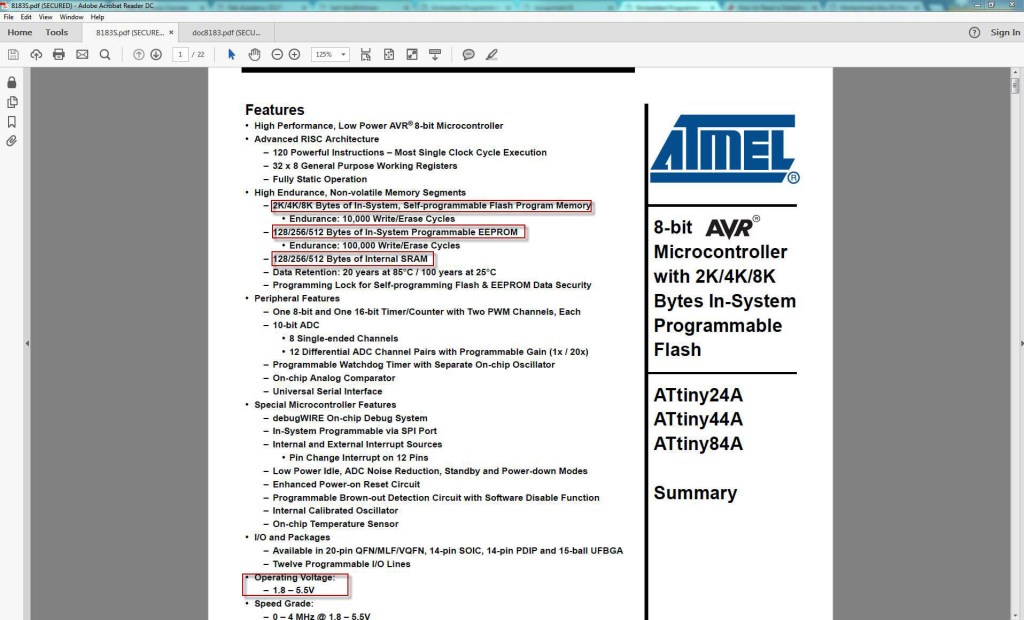
- FEATURES: The ATTiny44 is high Performance, low Power 8-bit Microcontroller with advanced RISC architecture, I found the following very useful:
- 2K/4K/8K Bytes of Flash Program Memory, 128/256/512 Bytes of Programmable EEPROM. 128/256/512 bytes SRAM.
- 12 general purpose I/O lines, 32 general purpose working registers and 8-channel 10-bit ADC.
- Internal calibrated oscillator.
- Operating voltage between 1.8 ~ 5.5V.
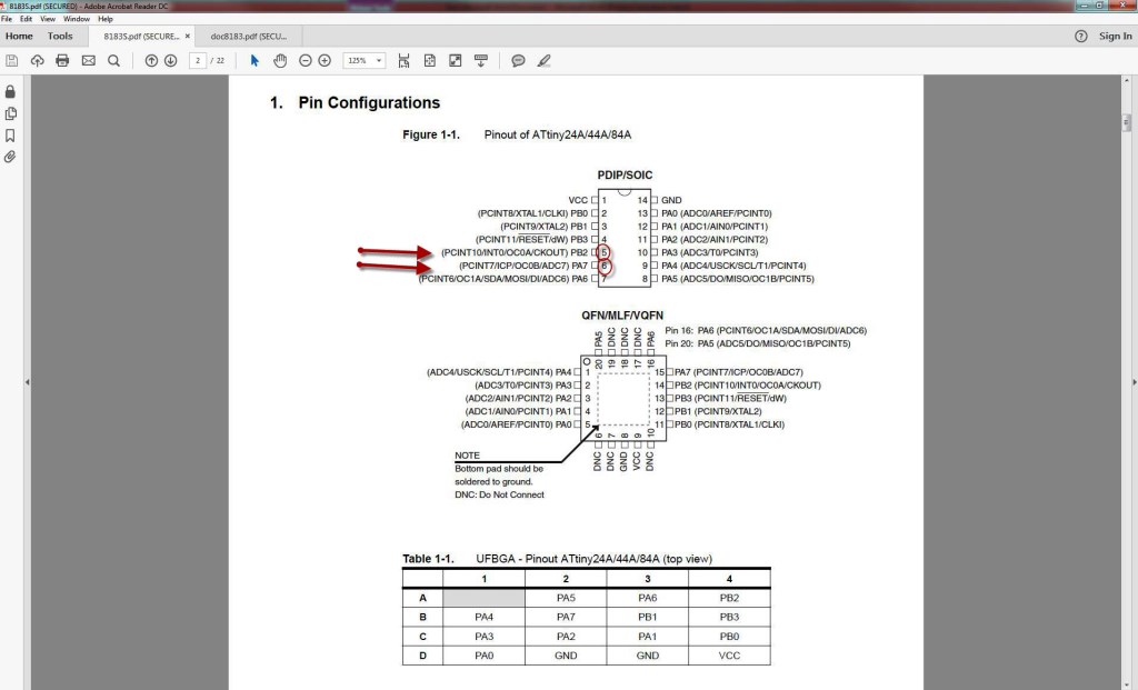
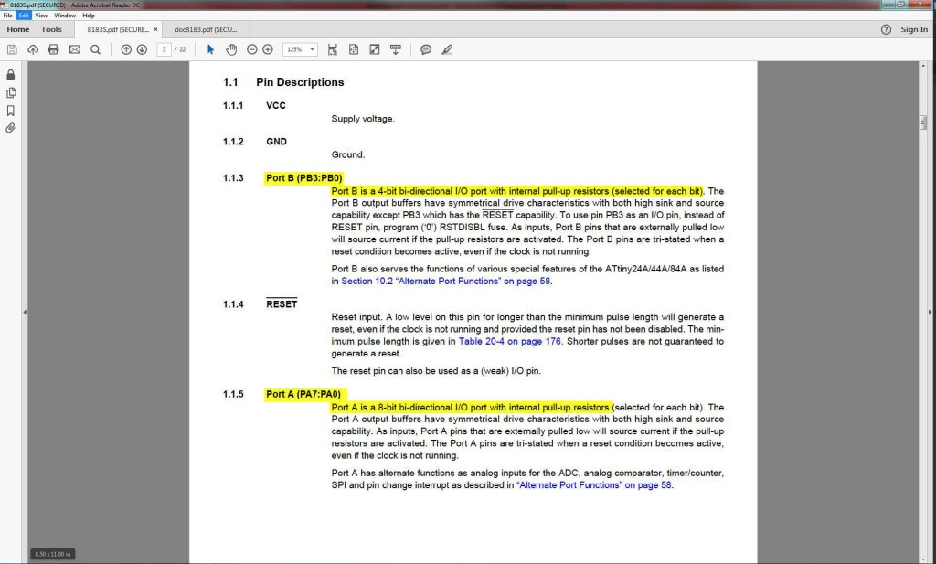
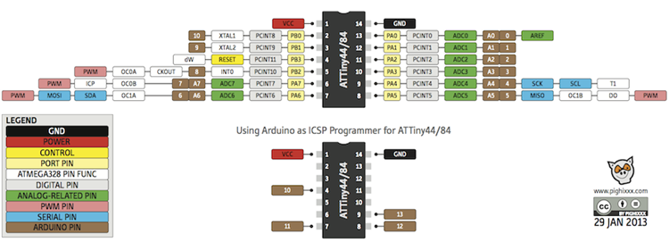
- It has two kinds of ports: Port A pins are 8-bit bi-directional I/O port with internal pull-up resistors (pin names are from PA0 to PA7) and Port B pins are 4-bit bi-directional I/O port with internal pull-up resistors(pin names are from PB0 to PB3).
- The Pin diagram and the Pin description are what you need to know when you program the board to know how to address the pins in C language and also whether you can assign this pin in Input mode or Output mode.
PROGRAMMING THE BOARD
To learn and experience different methodologies to program the micro-controllers, I decided to try 2 different ways as follows:
- METHOD (1): Using FAB ISP and Arduino IDE.
- METHOD (2): Using FAB ISP and WINAVR.
METHOD 1 - USING FAB ISP AND ARDUINO IDE
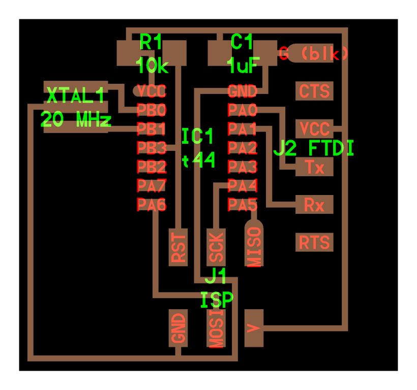
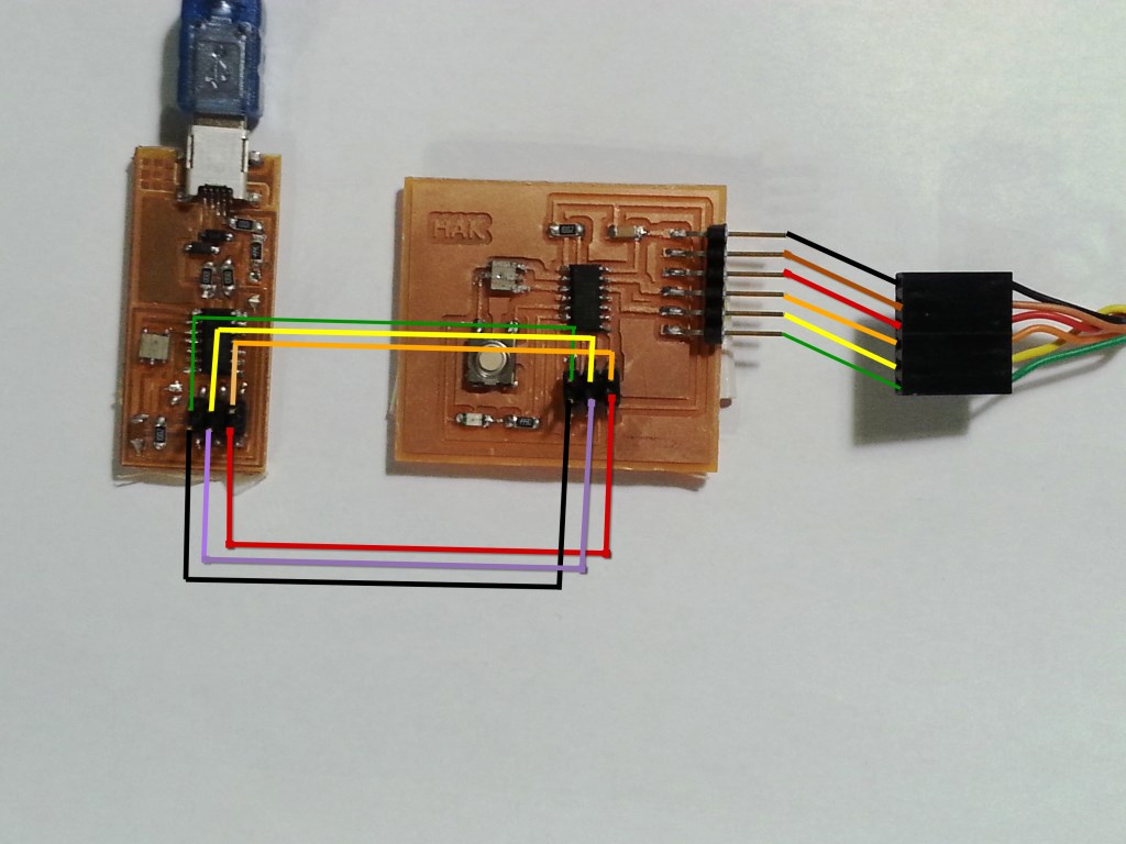
- Connect the FAB ISP pins to the Hello board pins with each pin connected to its corresponding similar pin as follows:
- MISO (in FAB ISP) -> MISO (in Hello Board)
- MOSI (in FAB ISP) -> MOSI (in Hello Board)
- SCK (in FAB ISP) -> SCK (in Hello Board)
- Vcc (in FAB ISP) -> Vcc (in Hello Board)
- GND (in FAB ISP) -> GND (in Hello Board)
- RST (in FAB ISP) -> RST (in Hello Board)
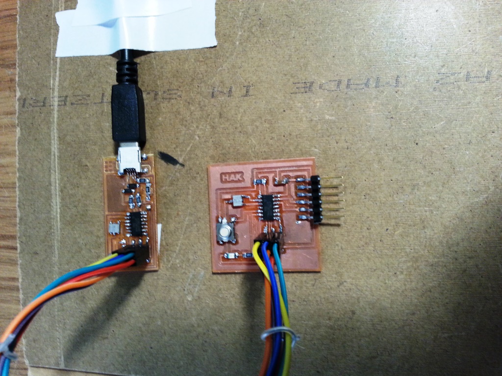
- Connect the FAB ISP to the usb Port and ensure it is detected by the PC.
- Connect the FTDI Cable to the FTDI header in the FTDI pins in the Hello-Echo Board.
- Download Arduino IDE from THIS LINK and install it
- I added support to the ATTINY44 to my arduino IDE by doing the following steps:
- Open File -> Preferences, Then, at the bottom of the pop up menu where you see "Additional Boards Manager URLs" copy and paste "https://raw.githubusercontent.com/damellis/attiny/ide-1.6.x-boards-manager/package_damellis_attiny_index.json" and click OK
- Go to Tools > Board > Board Manager, scroll down to the bottom and you should find "attiny". Click the install button and the words "Installed" should appear when the task is completed.
- To confirm that you have added support for the boards, navigate to Tools > Board and you should see ATtiny at the bottom of the list.
- To be able to upload a Sketch to the ATTINY 44, it is mandatory to burn the BOOTLOADER. So I followed the following steps:
- Select "USBtinyISP" under Tools > Programmer.
- Select ATtiny from Tools > Board.
- Select the specific ATtiny you are using (44/45/84/85) from Tools > Processor.
- Next select "20 MHz (External)" from Tools > Clock.
- select "Burn Bootloader" under tools and wait till it completes.
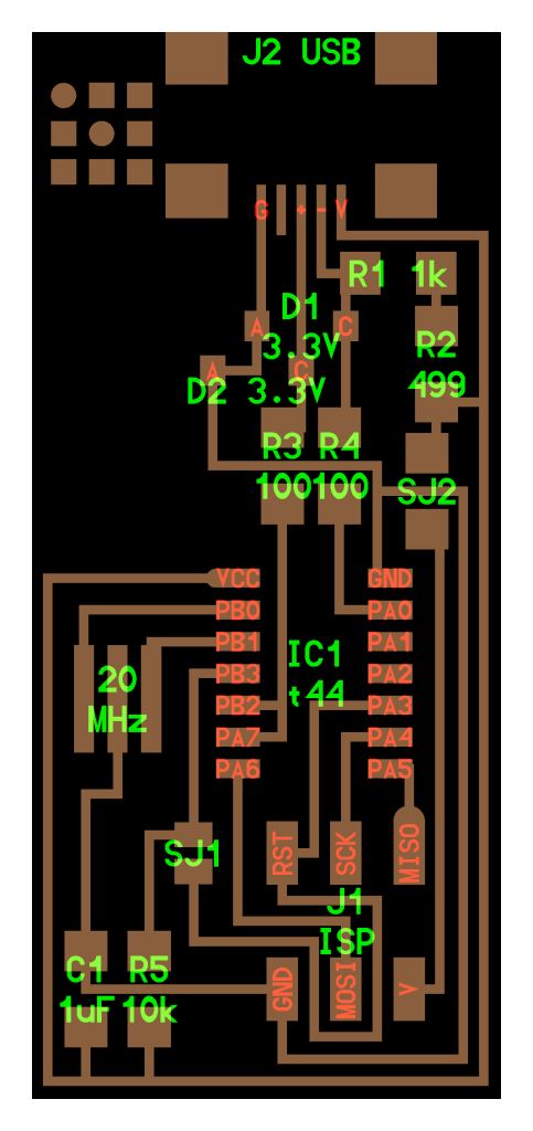
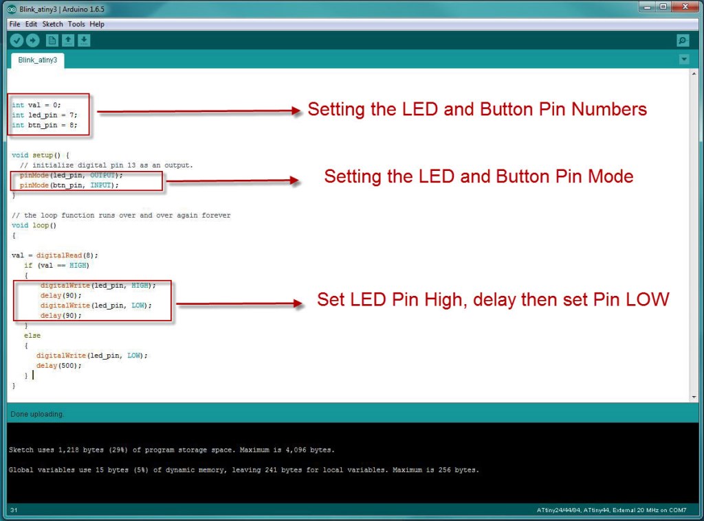
- I identified the ATTINY44 Pins that the button and the led are connected to and their corresponding mapping to them in Arduino IDE to be:
- LED -> ATTINY44 Pin = PA7 -> Arduino Pin = 7
- BUTTON -> ATTINY44 Pin = PB2 -> Arduino Pin = 8
- I wrote a simple code as shown below that blinks the led when the button is pressed and I uploaded it. I then disconnected the programmer and I ran the HELLO-ECHO board.
METHOD 2 - USING FAB ISP AND WINAVR
- Connect the FAB ISP pins to the Hello board pins with each pin connected to its corresponding similar pin as follows:
- MISO (in FAB ISP) -> MISO (in Hello Board)
- MOSI (in FAB ISP) -> MOSI (in Hello Board)
- SCK (in FAB ISP) -> SCK (in Hello Board)
- Vcc (in FAB ISP) -> Vcc (in Hello Board)
- GND (in FAB ISP) -> GND (in Hello Board)
- RST (in FAB ISP) -> RST (in Hello Board)
- Connect the FAB ISP to the usb Port and ensure it is detected by the PC.
- Connect the FTDI Cable to the FTDI header in the FTDI pins in the Hello-Echo Board.
WHAT IS FTDI AND WHAT FTDI CABLE I USED?
The FTDI cable is a USB to Serial (TTL level) converter which allows for a simple way to connect TTL interface devices to USB. The I/O pins of this FTDI cable are configured to operate at 5V. The FTDI cable is designed around an FT232RQ, which is housed in a USB A connector. The other side of the cable is terminated with 6-pin connector with the following pinout: RTS, RX, TX, 5V, CTS, GND (RTS is the green cable and GND is black). CLICK HERE to see the FTDI cable I used.
The FTDI cable is a USB to Serial (TTL level) converter which allows for a simple way to connect TTL interface devices to USB. The I/O pins of this FTDI cable are configured to operate at 5V. The FTDI cable is designed around an FT232RQ, which is housed in a USB A connector. The other side of the cable is terminated with 6-pin connector with the following pinout: RTS, RX, TX, 5V, CTS, GND (RTS is the green cable and GND is black). CLICK HERE to see the FTDI cable I used.
- Download WINAVR from THIS LINK and install it
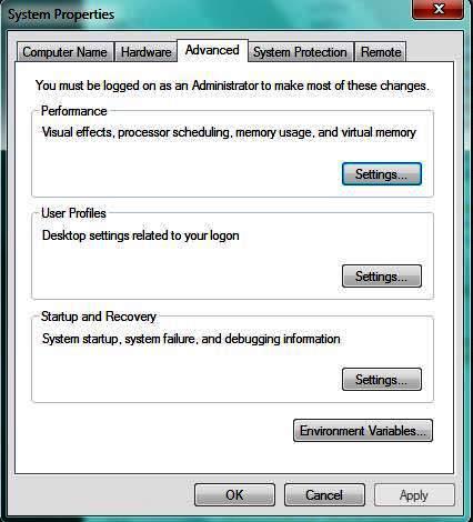
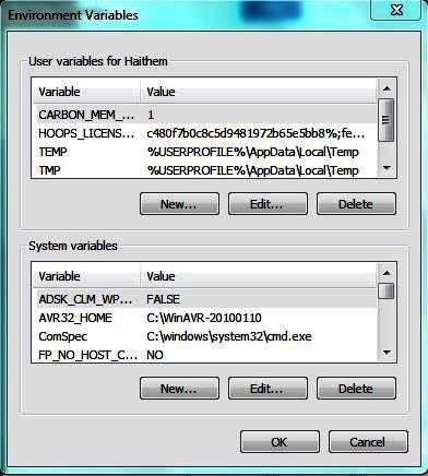
- In windows OS: Open System properties -> Click on Environment Variables -> Choose PATH variable and click EDIT and add the "C:\Winavr\bin"
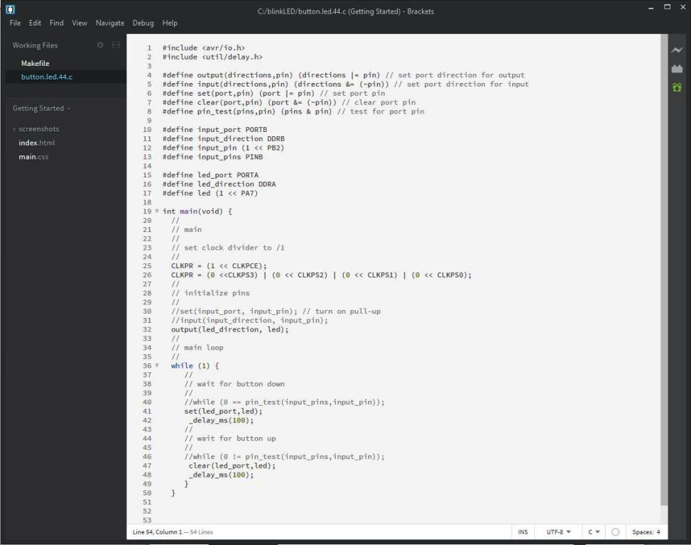
- I opened the code written by Mohammed Haggag in THIS LINK which was written based on "hello.RGB.45.c" from "Output Devices" and "hello.button.45.c" from "Input Devices", then I modified it to blink when the button is pressed.
- I opened brackets editor and started to type the following code and saved it as .C file, the .C file can be downloaded from HERE.
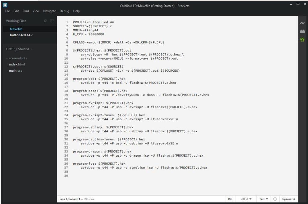
- In the barakets editor I created the following make file that can be found Here
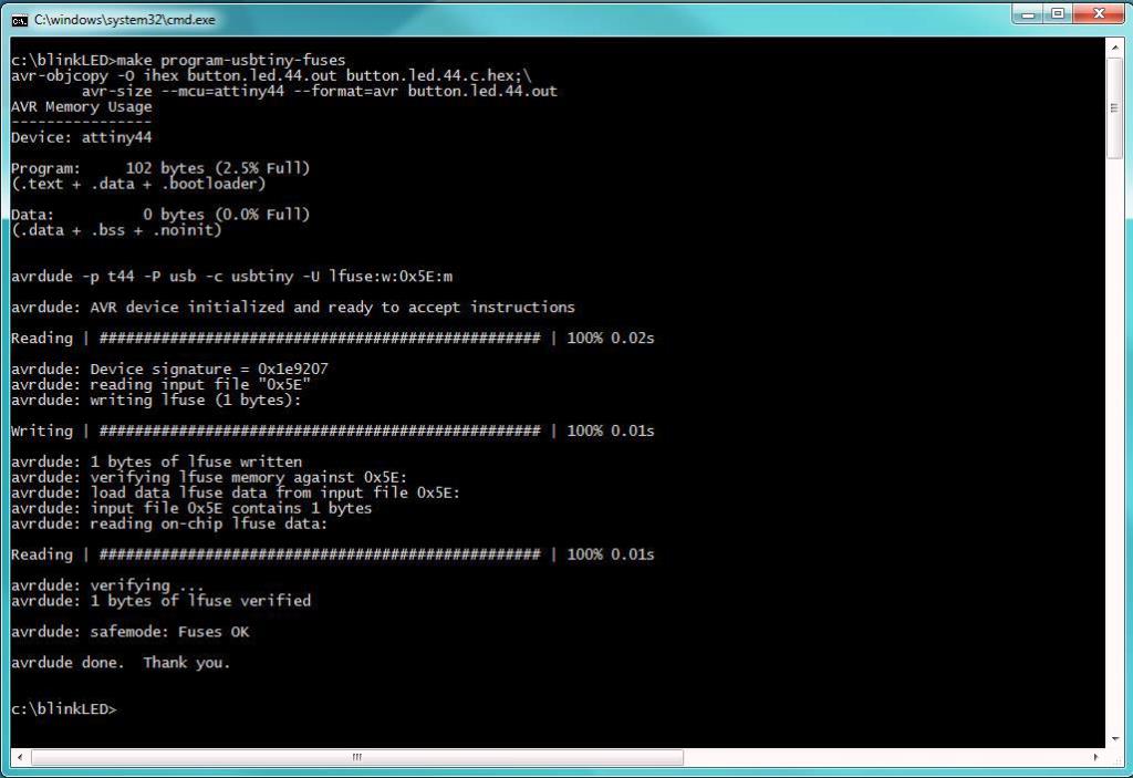
- In windows OS: Open the command prompt and go to the folder where the C file is saved then type the following commands.
- make program-usbtiny-fuses
- make program-usbtiny
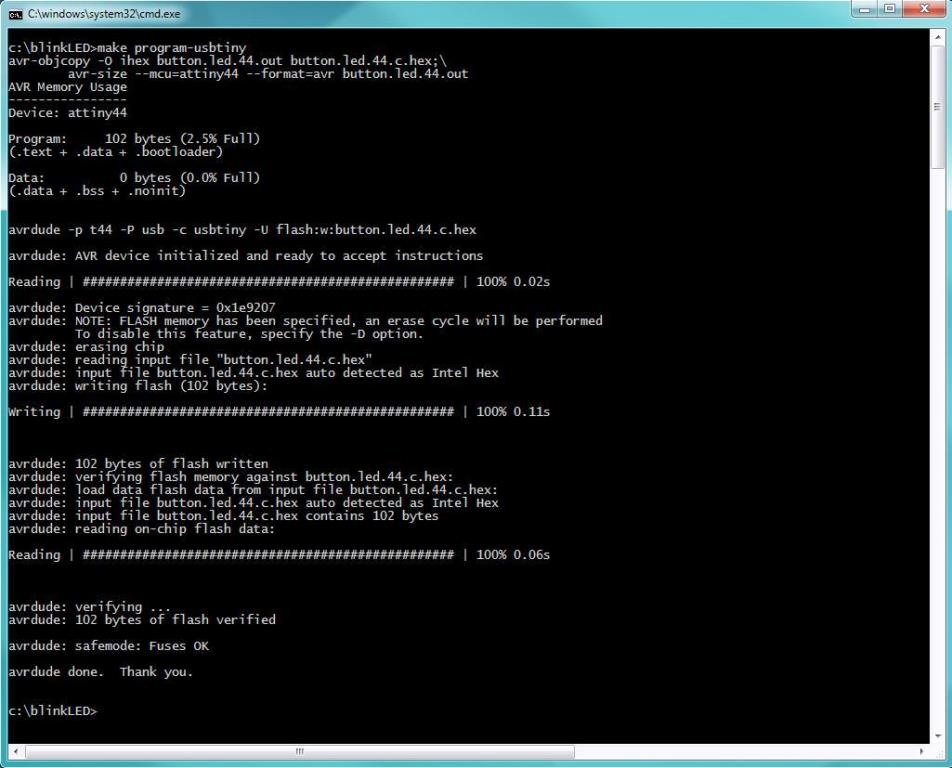
- Now disconnect the programmer and keep the FTDI cable connected to power up the board.
WHAT DID I LEARN?
This week I learned a lot of useful information that added to my knowledge and will definitely help me to fulfill the tasks I will need in my proposed final project specially that it will involve 2 different boards with different input and output devices. Few points I learned this week can be summarized as follows:
This week I learned a lot of useful information that added to my knowledge and will definitely help me to fulfill the tasks I will need in my proposed final project specially that it will involve 2 different boards with different input and output devices. Few points I learned this week can be summarized as follows:
- I learned how to read a datasheet, the typical contents in a datasheet and how to extract the important needed info.
- I learned that some of the ATTiny44 PINS has built-in pull-up resistors that can be configured to set the PIN to Signal to HIGH. This could have saved me a lot of hassle as in WEEK 7 ASSIGNMENT I did design the ATTiny pins connected to the GND and I thought that since the PIN is connected to the GND then it will never sense any change in state. I even did a RE-WORK to the PCB to fix that... this was not needed.
- I learned how to program a controller using ARDUNIO IDE and WINAVR.
- I learned the fact that using Arduino for programming introduce an overhead that is not needed to the memory since it include the arduino libraries, this can be avoided when I used the C-language. so for more effecient use of memory I will use Embedded C.
- I learned how to write simple C code for micro-controller.
WHAT I STILL NEED TO LEARN?- I believe since the memory in the ATTiny is limityed and as I need more memory to save the IR codes in my final project, I believe I will need to learn more about how to store info in the EEPROM.
Files: