Electronics Design
Task Requirments:
- group project: Use the test equipment in your lab to observe the operation of a microcontroller circuit board
- individual project: Redraw the echo hello-world board, add (at least) a button and LED (with current-limiting resistor), check the design rules, make it (if you have time this week, test it).
- optional: simulate its operation. Measure its operation
Redrwaing the Echo Hello World board
Eagle:
I started with Eagle tutorial on fab academy.
I faced a problem downloading the Fab library for eagle as the link opens an html file on browser, so i downloaded the linked file, then changed it's extension from .xml to .lbr
I also followed Abulhaggag assignment it was very detailed and useful.
Drawing the schematics:
List of components:
- 1 x ATTINY 44-ssu
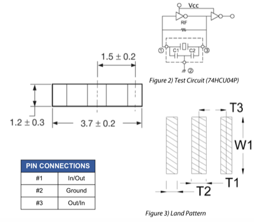
- 1 x Resonator
- 1 x AVRISPMD pin header
- 1 x FTDI pin header
- 1 x resistance 10K ohm
- 1 x capacitor 10uf
- 1 x push button
- 1 x LED
- 1 X resistance 499 ohm
Adding the components:
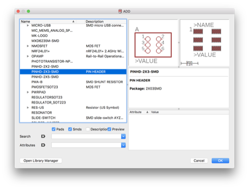
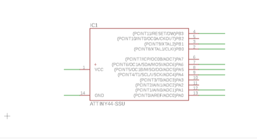
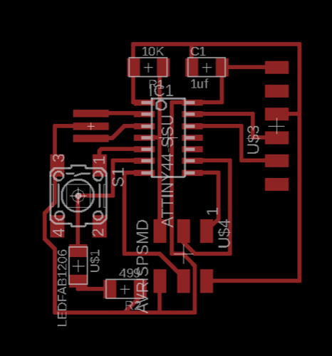
In the schematic view i added all the components from the fablab library and added supply VCC and GND. and i added a net "connection" to each leg that i want to connect, this is done by typing net in the upper bar and then drawing the net from the leg, i left all the nets un connected so i can connect them by naming.
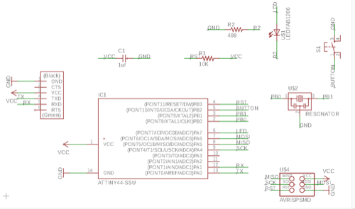
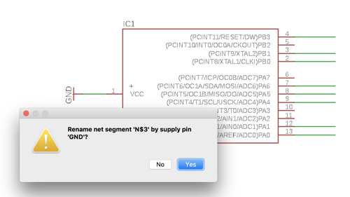
Naming the NETs
I named all the connected nets witht the same name, and eagle asks every time to make sure you want to connect them, just say yes.
N.B. For the resonator i had to open the data sheet to know which leg is GND
Arranging the components on board
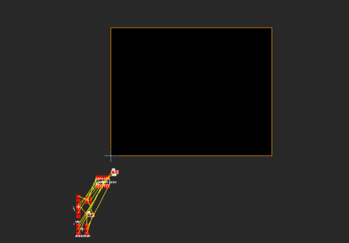
I moved all the components to the black working area by left click selecting all and then choose move and right click move group, then drag them all in the working area
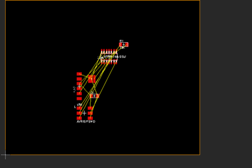
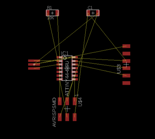
Using the yellow connection lines as a guide for connections i moved and rotated my components to the best possible way to optimize connections
Routing the traces:
I started to route the traces (16mil wide), it was a hard job until i found out the alt button to move in minor grids that made more easier and it went well.
Desing rule check DRC
I downloaded the DRC script from the academy tutorial page, then opened the tools menu, choose DRC and uploaded the script - Run and no errors :)
Making the board:
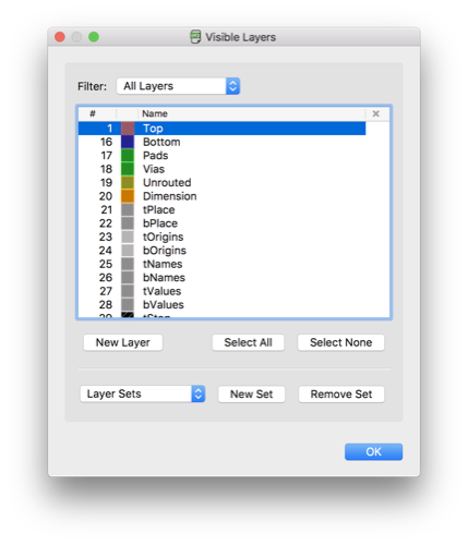
From the layers tab make only the top layer visible.
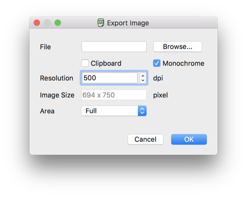
Export board as PNG with 500 DPI
Open image with GIMP
From Image canvas size add 20 pixels on width and height and center image.

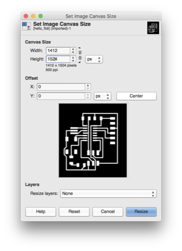
Flatten the image to make the borders white
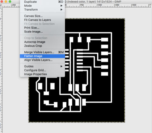
Save the image then paint the pads and traces black, from colors invert value and save the image as outline.
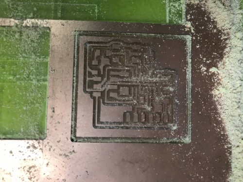
Import the PNGs to medela and enjoy the seen
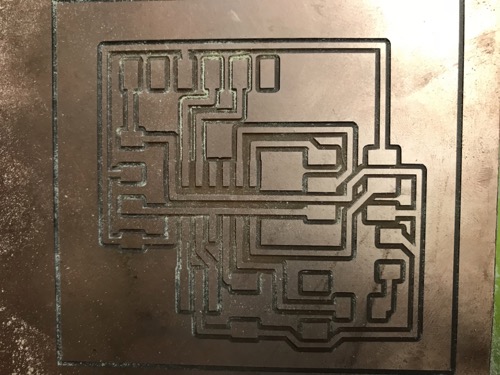
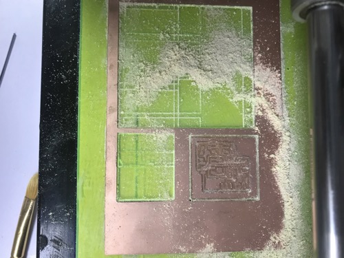
After Milling the board i discovered that the board scale is not ok the board was too big !!! after getting back to eagle and trying to export it again made sure it's 500 dpi, same dimensions - i tried to change the dpi but the board size is not changing !!! after many trials i exported the board and import it to another computer and opened it with eagle and export it to 500 dpi and it worked fine but still didn't figure out what's wrong.
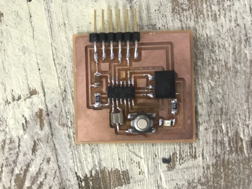
Soldering
Finally i soldered all the components and here it is !
Programming:
For Detailed programming steps of this board please refer to Embedded Programming Assignment.