Final Project...
Version 1
Version 2
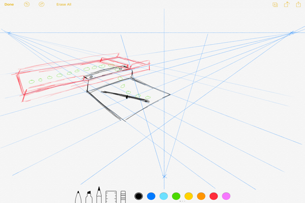
Idea and Concept
I have a cap assembley machine in my factory that assembles a 3 peices cap and release one by one on a conveyer that drops the cap into a box, The worker then has to take the full box and weight it to adjust the number of caps in the box and that takes time.
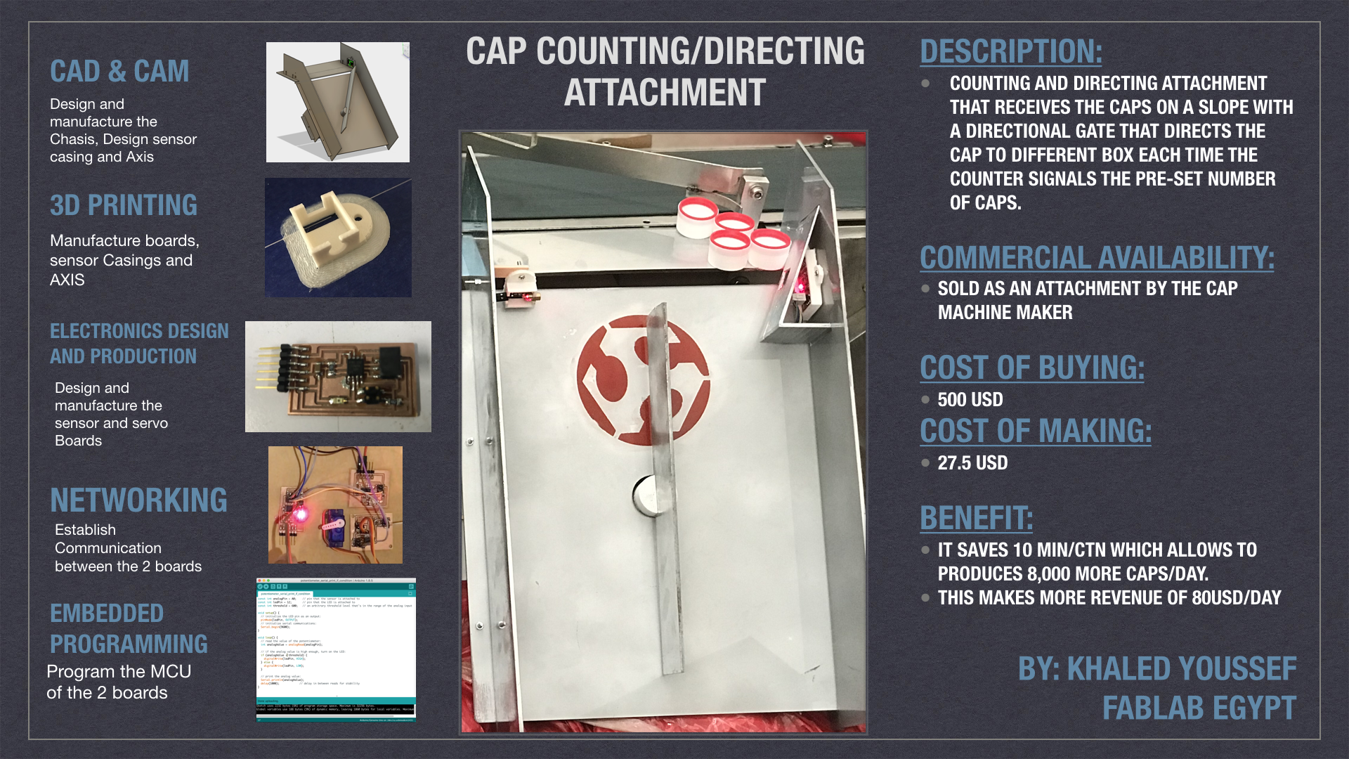
The Idea is to make a counting and directing attachment that receives the Caps on a slope with a directional gate that directs the cap to different box each time the counter signals the pre-set number of caps.
This Project Will Require the following skills:
- Cutting "to make the frame
- 3d Printing "for sensor and boards holders
- Embeded Programming and coding "to make the machine work"
- Input Devices "The counting Sensor"
- Output Devices "The Motor to control the gate"
There Fore I think it will meet the Academies requirments
Version 1
Bill Of Materials
| COMPONENT | COUNT | UNIT PRICE |
TOTAL PRICE |
VENDOR | NOTES |
|---|---|---|---|---|---|
| Laser Diode | 1 | 2 USD | 2 USD | Ram Electronics | Link |
| Attiny 45 | 1 | 1 USD | 1 USD | Farnell | |
| PhotoTransistor | 1 | 1.5 USD | 1.5 USD | Farnell | |
| 10K Ohm Resistors | 3 | 0.1 USD | 0.3 USD | Farnell | |
| Capacitor 1uf | 2 | 0.46 USD | 0.92 USD | Farnell | |
| Servo Motor | 1 | 3.5 USD | 3.5 USD | Ram Electronics | Link |
| Attiny 44 | 1 | 1 USD | 1 USD | Farnell | |
| Resonator 20MHZ | 1 | 0.5 USD | 0.5 USD | Farnell | |
| 3mm Plywood sheet | 4 | 0.5USD | 2USD | ||
| Total Cost | 13USD |
Parts and tasks:
- Chasis, which includes:
- Computer Aided design
- Digital manufacturing
- Assembling
- Input Device, which is a counting sensor and includes:
- PCB board with phototransistor "Design + manufacturing"
- Laser Diode module
- Case design
- Case Manufacturing
- Programming
- Output Device, which is a servo motor board and includes:
- PCB board to control the servo "Design + manufacturing"
- Servo Case design
- Servo Case Manufacturing
- Shaft Horn Design
- Shaft Horn manufacturing
- Programming
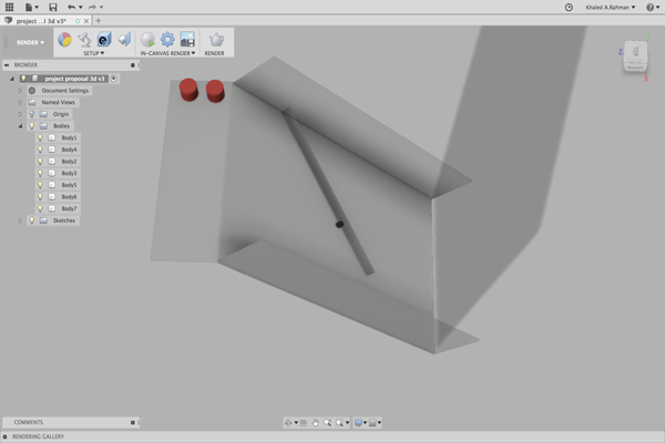
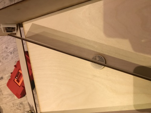
Chasis Design and fabrication:
I made the initial design in the CAD assignment
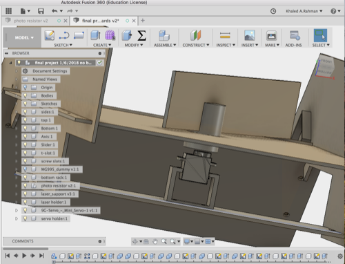
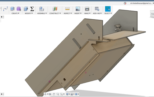
After finishing the design of the cases and holders for sensor and laser diode "will go through details after" i imported the all the parts to the design and i downloaded an STL for the servo from Thingverse, and i made some modifications for mounting the sensor and the servo motor.
and here is the final result
N.B. i had to remove the boards from the design before exporting as fusion don't accept export in f3d with linked boards.
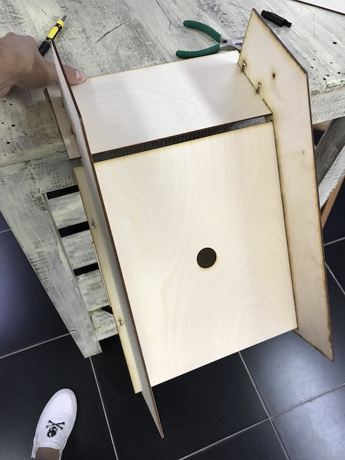
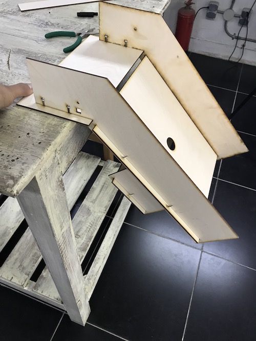
Chasis Manufacturing:
I Exported all the parts as DXF and laser cut it.
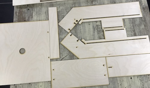
I assembled the chasis with M3 screws and nuts.
Input Device "Sensor" Design and fabrication:
I used the laser trap sensor that i fabricated in the Input Device Week use this link for details about the design and fabrication.
For the mounting of the sensor and laser diode to the machine i had to design and fabricate cases for both:
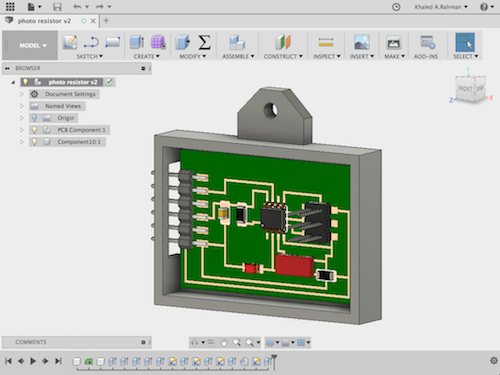
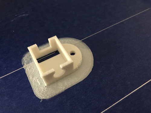
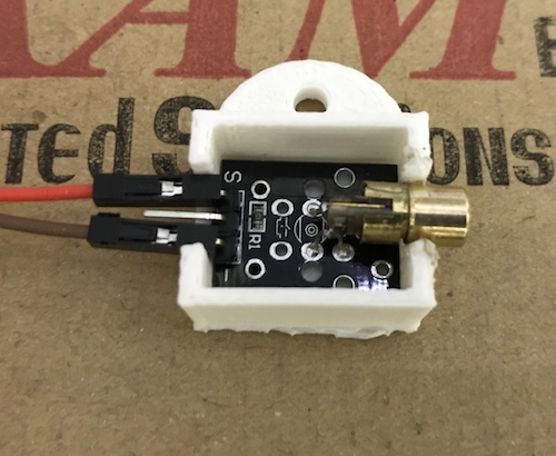
Sensor board case:
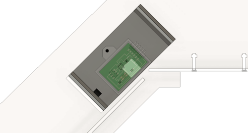
I Linked the board from eagle to the fusion project and i designed a holder which it will fit in and be mounted to the machine.
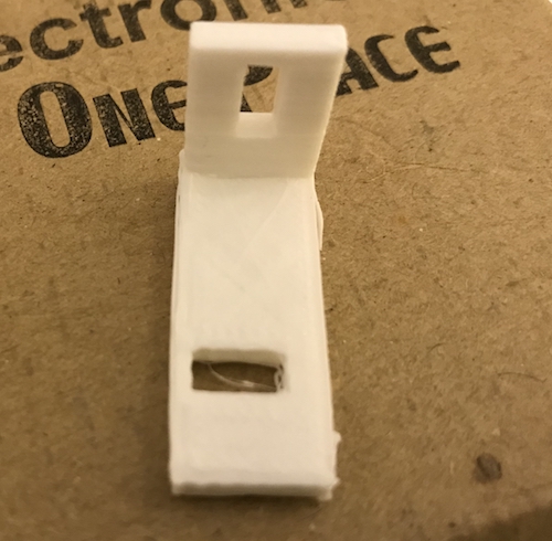
Laser Diode case
I downloaded this STL from Thingverse,i imported it to my project design in fusion and i designed a holder with stripes instead of holes to be able to adjust the laser beam on the phototransistor.
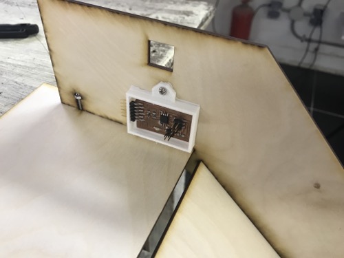
I 3D printed the 3 parts, and assembled it to the chasis.
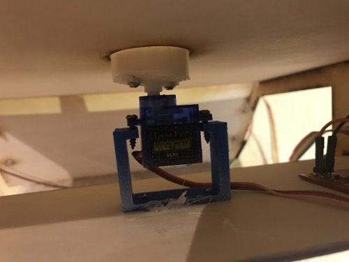
Output Device "Servo Motor" Design and fabrication:
I used the servo motor board that i fabricated in the Output Device Week use this link for details about the design and fabrication.
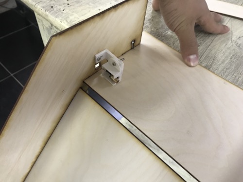
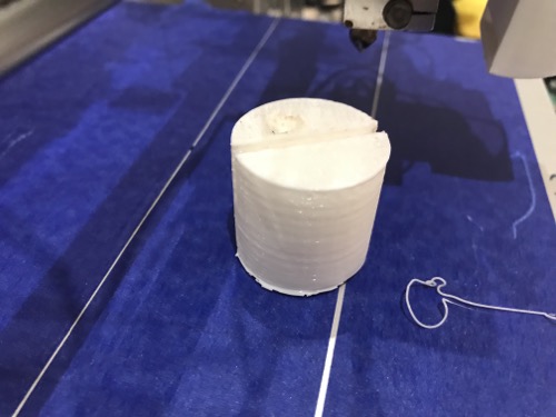
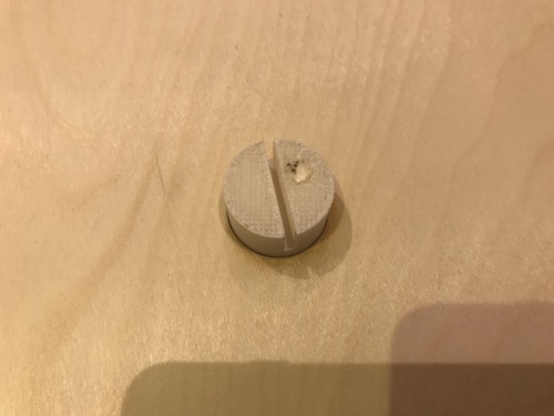
I designed a mounting holder for the servo. and i adjusted the size of the Axis designed before to fix it to the servo horn.
I printed the 2 parts and assembled them to the servo and with the chasis.
Programming:
Servo Board:
Controlling the Servo was a bit tricky as the servo didn't respond well to the software servo library.
I used the Software PWM servo motor code by neil as a building block for my code, I used the duty cycle delay values in the code to make my code on Arduino IDE
I kept trying different delays based on 2ms cycle duty until i reached the following values:
- Right angle: 1600mS High / 18400mS Low
- Left angle: 2000mS High / 18000mS Low
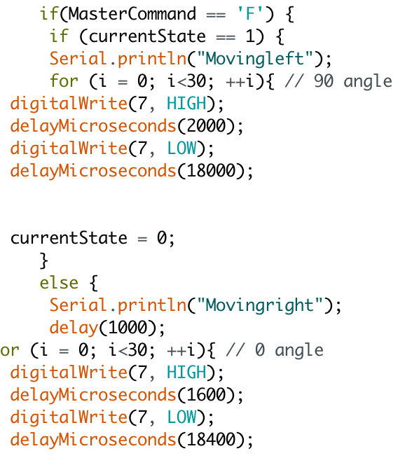
And here is the final code:
Sensor Board:
I used the code i wrote in the networking and communication week , and the Attachment is ready for testing
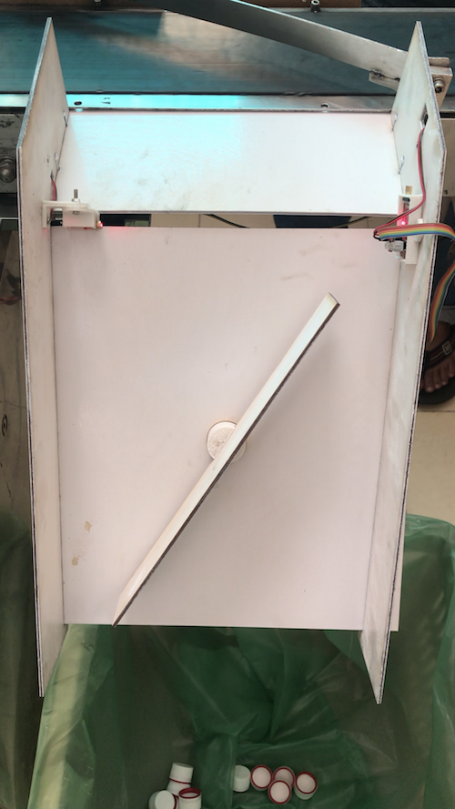
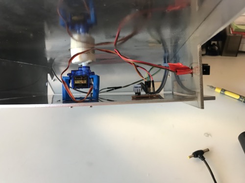
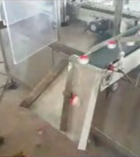
Final Stage "Attaching to the assembley machine":
I attached the attachment to the cap assembley machine.
After attaching to the machine the system didn't work, i connected the sensor board to the serial monitor and took the sensor readings and that was so different than the readings i got in the lab due to the strong ambient light in the factory.
so i changed the trigger and reset values in my code, and here is the final code:
And here is the final results:
Files:
Version 2
After installation of Version 1 there was some drawbacks in the design that needed improvments:
- The photoresistor was exposed so the effect of ambient light was very high and it required achange in the working range as mentioned before which affected machine stability.
- The Caps get stuck in the sensor casing
- The Wiring was not integerated in the design so it was exposed.
- The Material used "Wood" was rough which caused resistance to cap sliding and it was hard to clean which don't match the industry standards.
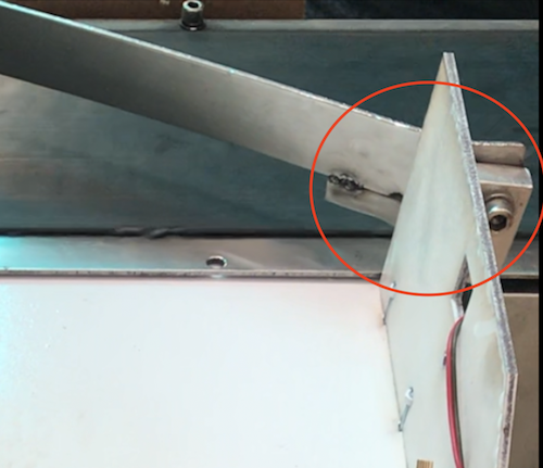
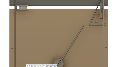
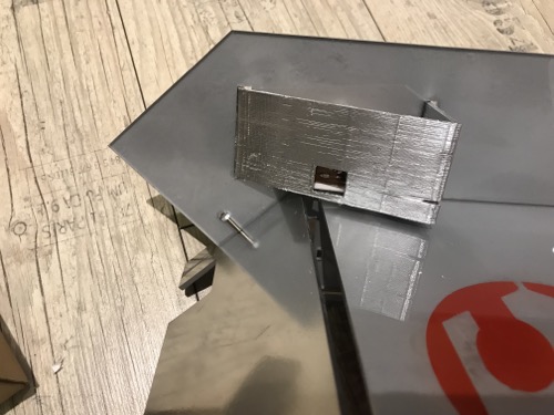
- Caps was ejected at the outermost corner of the attachment due to this protruding part in the main machine.
Redesigning:
I started redesigning with considerastion of the above drawbacks, and i made the following iterations:
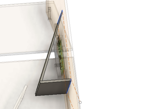
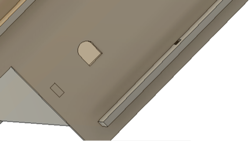
- I designed this sensor cover that will fix 2 main drawbacks in the old design, it will decrease the effect of ambient light significantly, and it's slope will help caps slide smoothly and prevent them from stucking, it will also provide protection to the sensor.
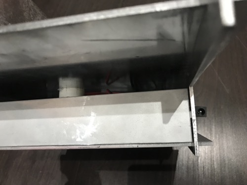
- I redesigned the whole chassis, making a closed box underneath the attachment which will hold all the boards, Motor and wirings, this way it will protect the wirings and the whole machine from unauthorizedn iteration from the unqualified operators. I also added a mounting place for the power socket.I also redesigned the 3d printed laser holder for wiring integeration.
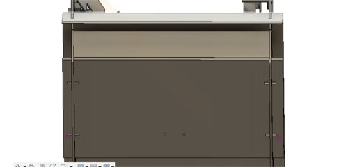
After This redesign the attachment is a closed plug n play attachment.
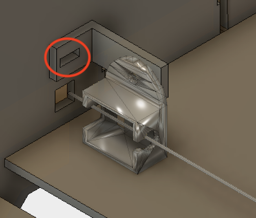
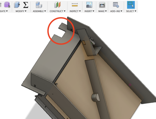
- Finally i made this groove in the attachment to snap into the main machine and solve the last drawback in the design.
Manufacturing:
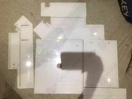
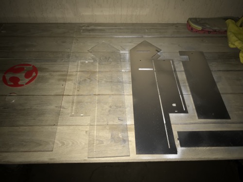
Laser cutting:
I laser cutted all the chassis parts, using acrylic this time for smooth operation and to match pharmaceutical industry standards.
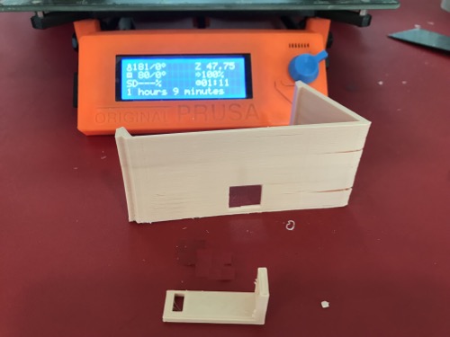
3d Printing
I 3d printed the new sensor cover and the redesigned laser holder.
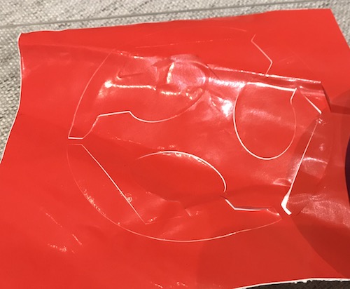
Vinyl Cutting:
I Cut the FABLAB logo on vinyl that i will use during painting my chassis.
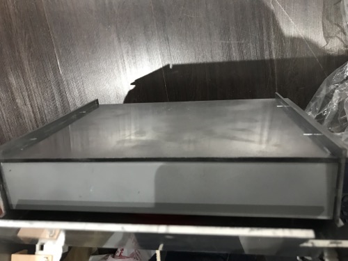
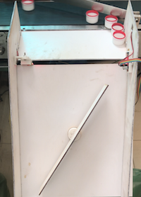
Painting and finishing:
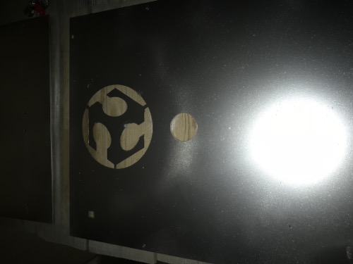
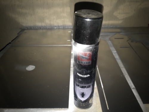
I decided to spray paint the back side of the chassis with silver chrome spray paint, thst will give nice metalic look and not affecting the functionality.
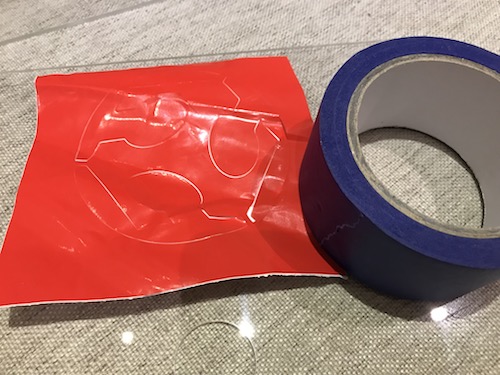
I will use the vinyl logo to leave an un-painted area that i will paint it red after finishing the chrome paint.
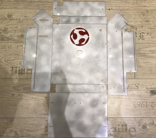
First i transfered the sticker to the bottom part, i didn't have a trsansfer tape so i used the 3D printer bluetape and it was a great substitute.
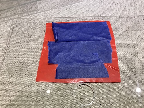
I painted all the parts with 2 light layers then removed the sticker
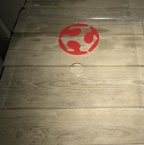
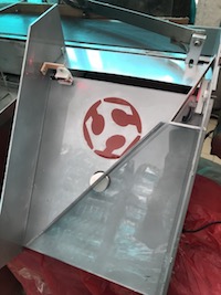
I painted the logo with red acrylic paint.
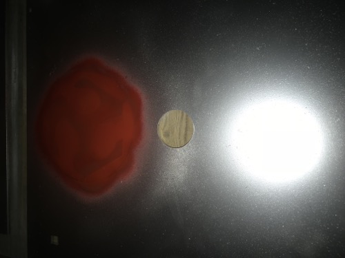
The 3d Printed sensor cover was a bit weak because i printed it with 5% infill, so i had the idea of painting it with wood glue and then finish paint it instead of pritning it again, and it worked great.
And here is the final result!
Assembley and installation
I assembled all the parts and installed the attachment to the machine.

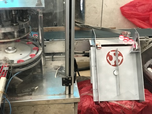
Testing:
And here it is in operation.
Important note: the flat area is designed to pile the caps to give the operator a chance to inspect the caps and pass them by hand, which is the technique already used before the installation of the attachment.
New Bill Of Materials
| COMPONENT | COUNT | UNIT PRICE |
TOTAL PRICE |
VENDOR | NOTES |
|---|---|---|---|---|---|
| Laser Diode | 1 | 2 USD | 2 USD | Ram Electronics | Link |
| Attiny 45 | 1 | 1 USD | 1 USD | Farnell | |
| PhotoTransistor | 1 | 1.5 USD | 1.5 USD | Farnell | |
| 10K Ohm Resistors | 3 | 0.1 USD | 0.3 USD | Farnell | |
| Capacitor 1uf | 2 | 0.46 USD | 0.92 USD | Farnell | |
| Servo Motor | 1 | 3.5 USD | 3.5 USD | Ram Electronics | Link |
| Attiny 44 | 1 | 1 USD | 1 USD | Farnell | |
| Resonator 20MHZ | 1 | 0.5 USD | 0.5 USD | Farnell | |
| 3mm Acrylic sheets | 5 | 5.5USD | 27.5USD | ||
| Total Cost | 38.5USD |
V2 Files:
| Commercial Version | Version 1 | Version 2 |
|---|---|---|
| |
|
|
ACKNOWLEDGEMENTS:
After This long hard trip i would like to pass my acknowledgments and gratitude to:
- My Local Instructors: May Eldardiry, your support and motivation was the fuel for this journey. Mohamed Abu Elhaggag all this wouldn't have been done without your sincere guidance, support and your most appreciated dedication.
- My Global Instructor: Ohad MeyuhasYour commitment and Challenges pushed us to get the best out of our selves.
- My Global Evaluator: Francisco, You really pushed me to the limit and this final project wouldn't have been like this without your guidance, THANKS.
- My colleagues: It was fun to work with you all, Haithem Abdelkhalek it was really pleasurable to ride with you on this trip, i think we wrere the light for each others in the darkest moments.
- Finally my wife:Thank you for your continous support and motivation during this long journey with many sleeples nights and weekends full of work. I LOVE YOU.