Computer Aided Design
Introduction
We were asked to model (draw, render, animate, simulate, ...) a possible final project.
To be honest I can't settle on a specific design that I'll implement for the final project.
2D Part:
I used Inkscape, to draw my model cause I worked previously on corelDraw, illustrator, photoshop and heared a lot about inkscape and I wanted to use it.
I read an article about the difference between corelDraw & Inkscape in this link. and I found out that it's somehow similar to corelDraw.
then with the aid of this simple video
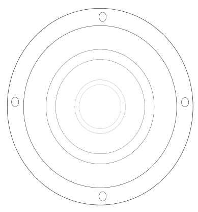
I reached this simple and fast sketch:
and if you wonder how to make something similar to it here's a short video I made using screen recorder:
- CTRL+D : doubles the copied items.
- CTRL+mouse drag: moves the object
- CTRL+SHIFT+mouse drag: resizes the part from all edges like the video ( must show the resizing arrows)
Steps:
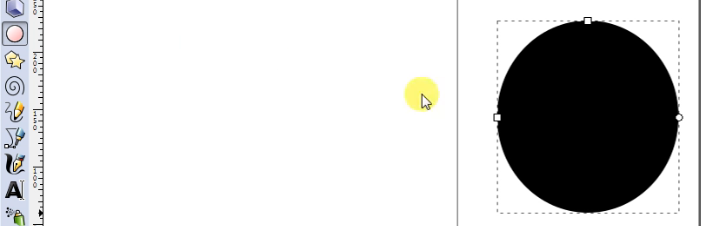
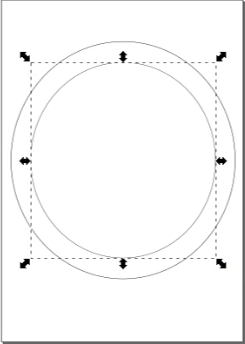
First draw a circle
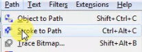
Next you have to select stroke to path option (CTRL-ALT-C) to make it only a frame not a filled circle.
Next click on the select cursor to adjust the circle dimension.

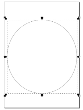
from this bar you can adjust the dimensions and the X & Y location on the sketch you made.

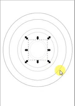
then I copied and pasted several time the circle and by using (CTRL+SHIFT+mouse drag) I resize it since I'm not sticking to a certain dimension.
lastly I repeated the process of resizing by selecting the two drawn orbits and make smaller versions of them.
3D Part:
Why Fusion 360?
- I chose Fusion 360 because I have no pirior knowledge about how to use it, so it would be enriching experience to learn about it.
- Fusion have all the desired (draw, render, animate, simulate, ...etc) to do in the assignment, also feature of having my files on cloud was a plus.
- Next assignment needs a parametric software and fusion is a parametric design software. Still asking why?
Installing
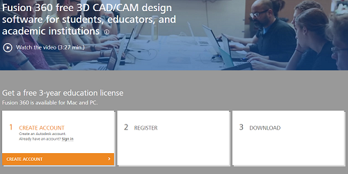
First, you have to download the software from Autodesk website
Secondly, you create account if you don't have then register and download as student in my case.
Drawing:
If you do not have any pirior knowledge about Fusion just like me...I advice you to go to Fusion360 channel on youtube and check their tutorials
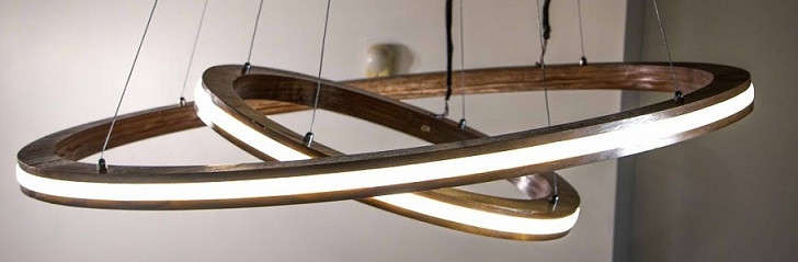
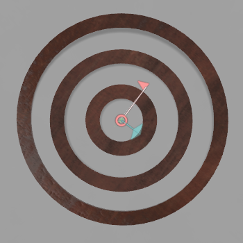
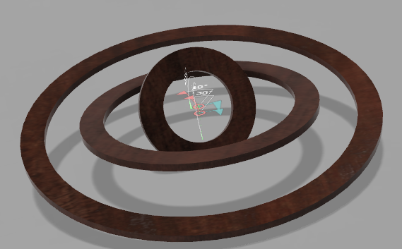
I started by drawing the orbits of the chandlier:
Joint is relation between two or more parts that make them respond relative to each other to an extent.
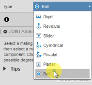
I used this reference from auto desk to make the ball joint.
After Clicking on the joint feature, you should select the two items you wish to apply the feature to
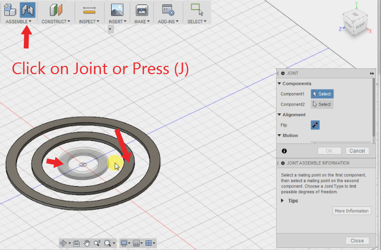
Choose the ball feature
Results:
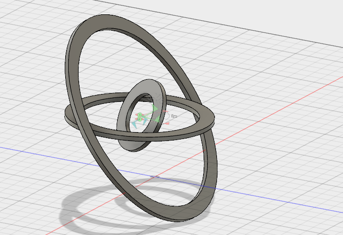
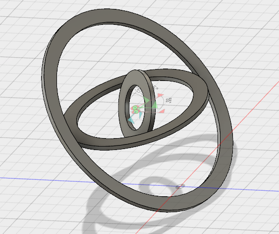
If you can't imagine why the orbits are not connected. Here is why:
honestly I forgot to add holes to the design and got overwhelmed by the ball joint.
so I added it here, but you don't have to do that if you drawed the sketch with circles as holes, so when you extrude the model holes will be made.
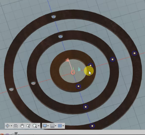
First, you draw circles normal circles in the places you want to make the holes in:
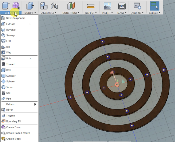
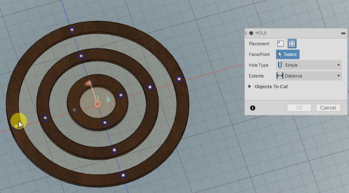
Second, you have to click on the Hole tool (H) then select all the circles you drew before, and customize the depth:
lastly, you click ok to confrim the hole making:
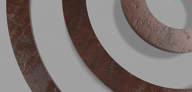
Rendering:
Rendering simply is having a photo-realtistic object with the finest details you could find on real object with the desired material.
In the video below you can find how to: (in the first 1 min the rest are different experiments in rendering)
1-Render
2-How to change object material characteristics (Wood, metal, plastic,....etc)
Here's how to render:
Last part (Animation):
Animation for some orbits won't be intresting like the tutorial I learnt from.
Files:
Fusion file
SVG file