Molding and Casting
This week we was required to work on Molding (or Moulding) and Casting, but now you might wonder what is Molding or Casting.
Molding: is the process of making a hollowed-out block that is filled with a liquid or pliable material such as plastic, glass, metal, or ceramic. The liquid hardens or sets inside the mold, adopting its shape.
Casting: is a manufacturing process in which a liquid material is usually poured into a mold you made earlier, which contains a hollow cavity of the desired shape, and then allowed to solidify. The solidified part is also known as a casting, which is ejected or broken out of the mold to complete the process. Casting materials are putting two or more components together; examples are epoxy whic I used in the assignment.
Design :
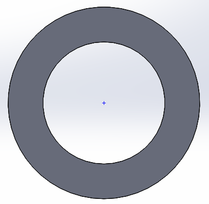
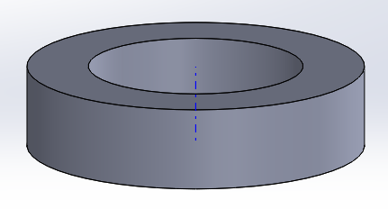
My design was a tiny ring (or orbit) as a early test for the final project orbit(s) I'll make.
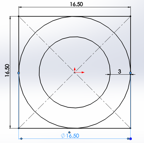
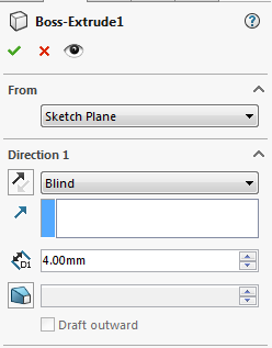
and I extruded the mold for a depth of 4mm, but I recommend you to make it more if you want.

lastly, you have to export the file as an STL (What's is STL is mentioned in 3D scanning and printing week)
The deeper the extrusion the more easier you pull the casted object from the mold.
What is the difference between 2D, 2.5d and 3D contouring?
My global evaluator Fransico, pointed out about what's 2D, 2.5D and 3D molds and how my ring is just 2.5D mold.
So I read this article that descirbes the difference and decided to make 3D tool path as well, but won't mill it, for the sake of pure learning.
Machining: (SRP Player) (2.5D ToolPath)
You have to install the SRP Player which's the software responsible for giving cutting instructions to the CNC machine (Modella MDX-40A) and this software is provided by the manufacturer in a form of a CD.
- You have to open the stl file, click on CTRL + O and select the file
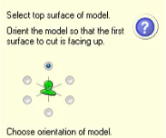
- make sure you select the orientation you want for you item.
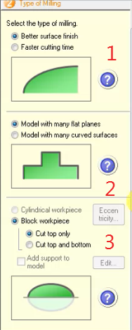
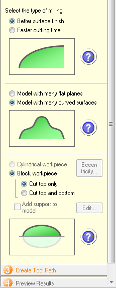
- You have to select the type of milling
- This option defines whether you aim for quality or time
- This option defines whether flat surface with a flat end mill usage or curved surface with ball point end mill to smoothin the curves.
- This option for my machine is top only. Because the top and bottom option is used when the machine's bed can rotate and access the lower part of your mold block.
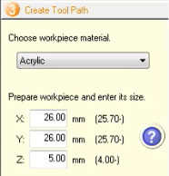
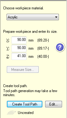
- Choose the material of your mold and it's size because hard materials such as acrylic the end mill needs several steps to cut to the desired depth, maybe in less hard material you can go down the desired depth in 1 time.
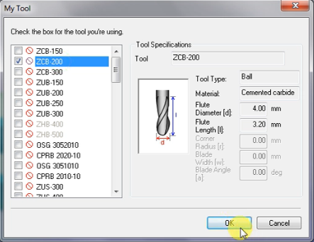
- Before generating the tool path you have to select the end mill (tool) you'll use.
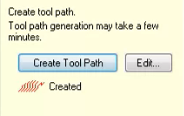
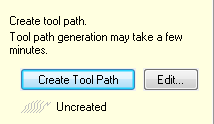
- Click on Create tool Path
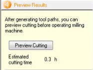
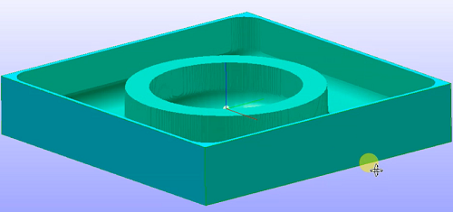
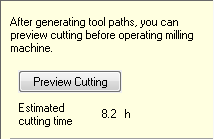
- This page shows the time estimated for milling and click on preview cutting to visualize what the milling will do.
- Lastly, if the preview looks as desired you can switch to the machine control axis software called V-Panel and prepare it then click on start cutting.
Machining: (SRP Player) (3D ToolPath)
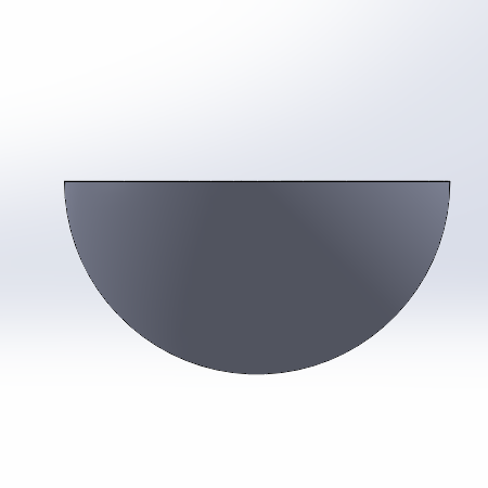
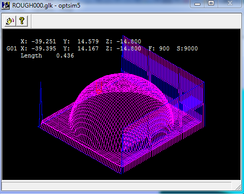
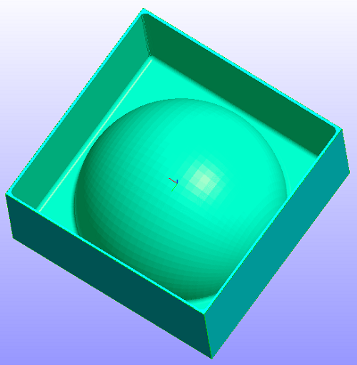
I used a simple, yet a 3D shape that will allow me to make a 3D toolpath which is a hemi-sphere that I saved in the STL format from SolidWorks.
- You have to open the stl file, click on CTRL + O and select the file
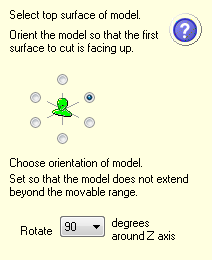
- make sure you select the orientation you want for you item.
- Then you have to select the settings of milling
- The first option defines whether you aim for quality or time
- This second option defines whether flat surface with a flat end mill usage or curved surface with ball point end mill to smoothin the curves.
- This third option for my machine is top only. Because the top and bottom option is used when the machine's bed can rotate and access the lower part of your mold block.
- Choose the material of your mold and it's size because hard materials such as acrylic the end mill needs several steps to cut to the desired depth, maybe in less hard material you can go down the desired depth in 1 time.
- Before generating the tool path you have to select the end mill (tool) you'll use.
- Click on Create tool Path
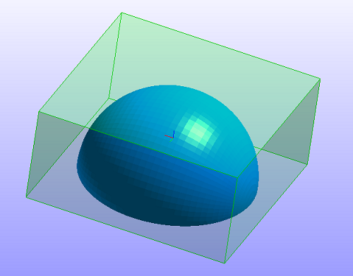
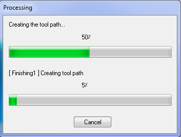
- This page shows the time estimated for milling and click on preview cutting to visualize what the milling will do.
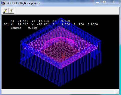
- When you click on Preview Cutting a small window appears in long processing operations like this to show show the toolpath, in 2.5D it didn't appear because the processing was extremely fast and easy.
- Lastly, if the preview looks as desired you can switch to the machine control axis software called V-Panel and prepare it then click on start cutting.
Machining: (VPanel)
This's the interface of VPanel and it doesn't open until you connect the machine to your personal device.
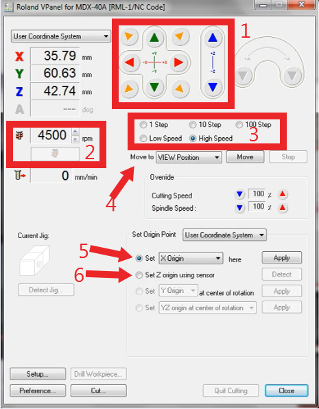
In the picture below I pointed out the most important things you might need and I'll explain them.
- This part is responsible of moving the 3 axis manually in all directions
- This part is used to test the speed of the spindle and can vary it's rotaion per minute (rpm)
- This part is also related to part 1; because it defines the speed the you can move the axis with
- This part is the automated movement part that after you use part 5 to set the X,Y,Z or Origin you can move to them automatically without any extra manual effort.
- This part is used to set the X,Y,Z or Origin then you can move to them automatically.
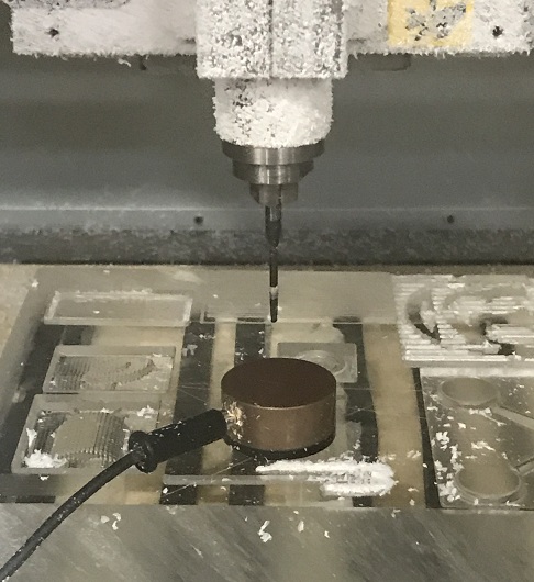
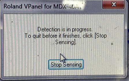
- (Optional) This part sets the Z axis origin by putting a sensor on the item you want to mill.
Molding Output:
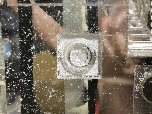
We use this acrylic mold to make silicon mold and cast in it the epoxy and get our final product.WHY?!
Because you can't pour epoxy directly into acrylic this means you'll pour solid material into another one (Acrylic & Epoxy) and they'll become unsepratable that's why we use silicon which's a pliable material.
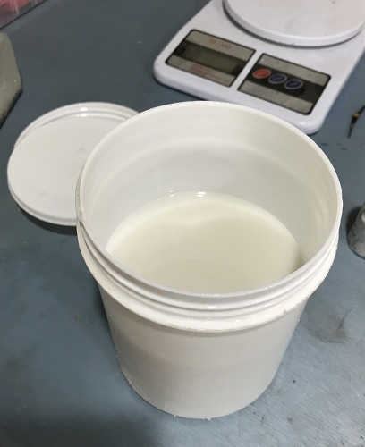
You should have sillicon and it's hardner material.
Silicon:
Silicon-Hardner: (The 3 percent written indicates the ratio.)
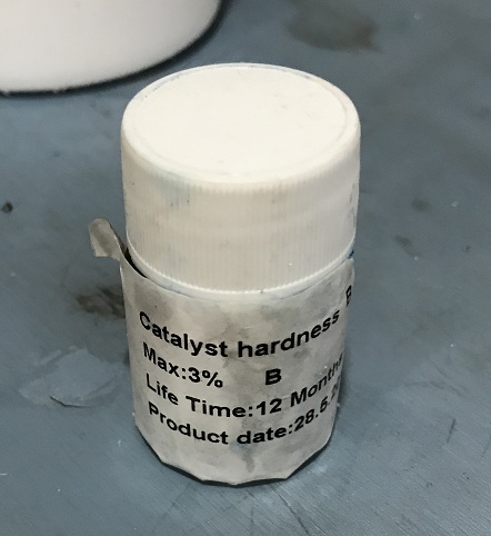
As you can see upward the hardner ratio is 3% of the volume used, so if you used 100g for your mold then you need 3g from the hardner.
Before pouring the silicon make sure the area you'll pour in is clean.
After pouring the silicon mixture make sure you apply force over it to relese bubbles that might deform your mold and let the silicon harden.
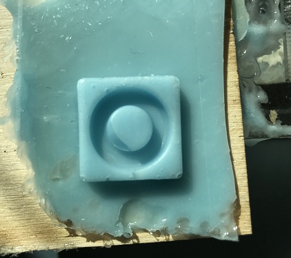
After 1 day this was the output:
Casting:
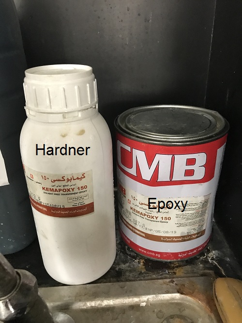
As I mentioned before we will use Epoxy as the final material for our design.
Epoxy with it's hardner: (It's a fixed ratio in epoxy150 (150 refers to its chemical characteristics) material.
(2 Epoxy : 1 Hardner))
The process went like this:
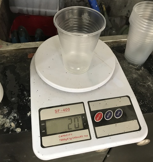
- Bring 2*(Amount) of epoxy
- Bring (Amount) of it's hardner
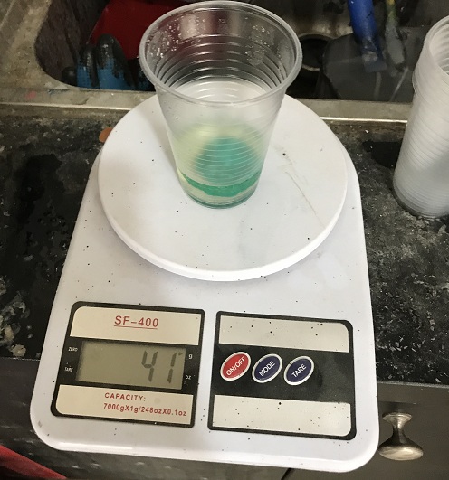
- (Optional) Add color die
- Mix them and pour gently into the silicon mold.
My advice is to pour from a high distance above the mold to ensure smooth thin pouring that will lead to least amount of air bubbles the act as deficits in your casted part.
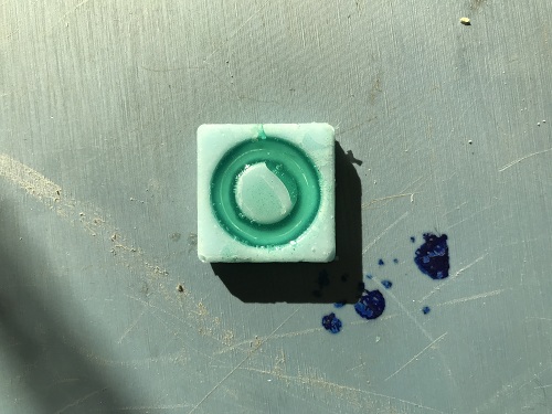
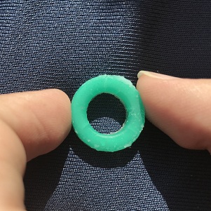
Final Result :
As you can see in my silicon mold there's a missing part in the circle that in my design I could've easily removed using a grinding tool, yet this fault is due to air bubbles and the most basic way to do that is to hit the mold on a bench or ground several time to ensure air bubbles came from the bottom to the top and your silicon made it to the bottom of your mold.
To know how to get rid of bubbles I've found those 2 excellent sources:
Shows how to get rid and how to pour on the mold
4 easy ways to get rid of air bubbles
Download Files:
SolidWorks Design File and STL Export(.SPJ) Files and toolpaths (2.5D, 3D)