Computer-Controlled Cutting Computer-Controlled Cutting With OpenSource World
Assignment 4
group assignment:
characterize your lasercutter, making test part(s)
that vary cutting settings and dimensions
individual assignment:
cut something on the vinylcutter design, lasercut, and document a parametric press-fit construction kit,
accounting for the lasercutter kerf, which can be assembled in multiple ways
So my first Challenge is starting with the drawing in CAD the Pressfit Kit
So from the last assignment , I worked with 3 Softwares Freecad , Openscad , Solvespace As i designed the final Project in freecad .. I descided to use the Solvespace as a parametric design software ..
I start drawing like you will find in this video ..
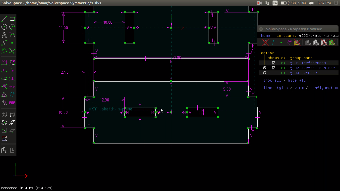
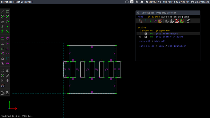
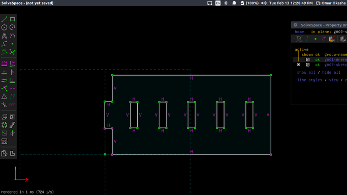
This is design with full dimenstions without constains ..
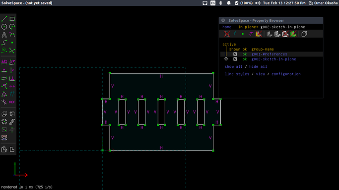
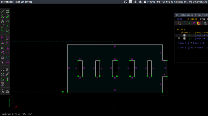
This is design with full constrains and dimensions ..
This is the Comp ..
this is the output at last ..
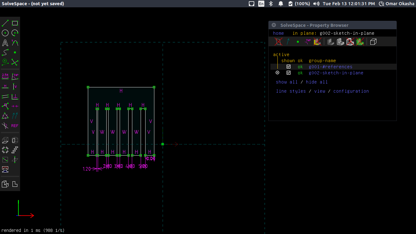
This is the Comp to Measure the Thickness
There were shocking thing after I finised drawing I asked my Instructors ..
Is this Parametric Design when we put constrains in the drawing and assign some values and by changing them the whole draw will react to changes ..
That was not a Parametric Design ..
So I Descided to dig for a crazy trip with Openscad and I started working to draw the whole part in Cartisien by draw it in polygon ..
and this was really a trip ..
So in openscad we are dealing with points and that is a not normal thing in cad design ..
as we want to make it parametric .. so we will want to set variables ..
like this
y=10;// The Y Diemnsion
fit=2.9; // The pressfit Parameter part of X Dimension
width=80; // The width of the Plate part of X Dimension
x0=0;//Postion for the whole plate for x
y0=0;//Position for the whole plate for y
kerf = 0.1;
then I started to design array of equation for each point of my design ..
standard_piece=[
[x0 -kerf/2,y0+y-kerf/2],               //left edge
[x0-kerf/2 ,    y0+kerf/2+y*2],         //left edge
[fit+x0-kerf/2, kerf/2+y0+y*2],         //left edge
[ fit+x0-kerf/2, kerf/2+y0+y*3],        //main square
[ fit+x0+width+kerf/2,kerf/2 +y0+y*3],  //main square
[ fit+x0+width+kerf/2, kerf/2+y0+y*2],  //right edge
[ 2*fit+x0+width+kerf/2,kerf/2 +y0+y*2],//right edge
[ 2*fit+x0+width+kerf/2, y-kerf/2+y0],  //right edge
[fit+x0+width+kerf/2, y-kerf/2+y0],     //right edge
[fit+x0+width+kerf/2, y0-kerf/2],       //main square
[ fit+x0-kerf/2, +y0-kerf/2],           //main square
[ fit+x0-kerf/2,   +y+y0-kerf/2]];      //left edge
This is the Screencast for the Phase of Designing
And this is the Final Design
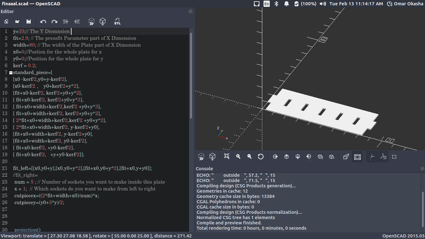
This is the power of Parametric Design and OpenScad :) :)
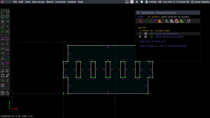
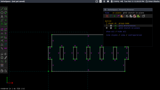
I started to export DXF from Openscads .. Those are the DXFs Files that used with lasercut opened by Solvespace
#1
#2
#3
#4
#5
#6
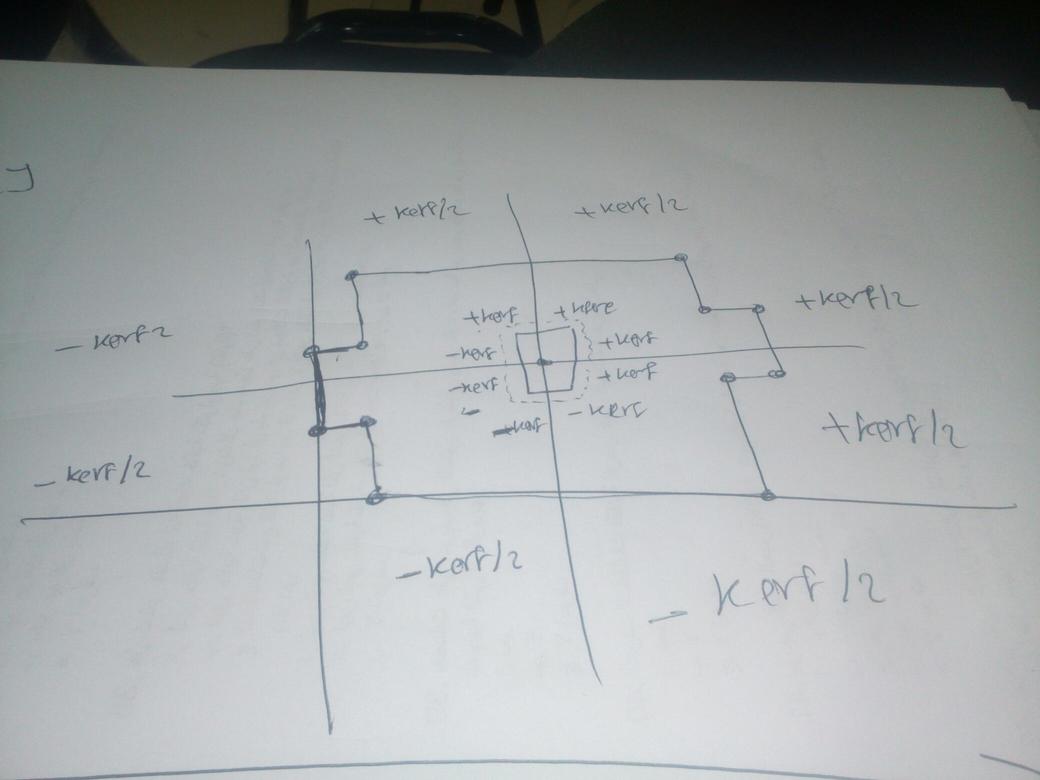
How did i get those equations by drawing in paper first .. and try to put each point in parameters .. In normal operation with kerf and CAD .. for outside of the part we add the kerf/2 for the inner sockets we subtract kerf ..
and the last code was the final code .. As I was working in another fablab "Fab Lab In New Cairo " that have Laser cutter machine and viynl cutter So I made the Full Characterization Alone :) ..
So I start characterize the laser cutter ..
Start preparing the RDWorks as I have a previous Experience with RDWorks so I start draw a file on RDWorks
This is a quick arabic tutorial I made for RDWorks ..
RDWorks is very simple 2D design software ..
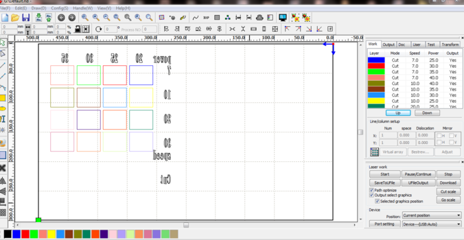
I start working on making 2D squares 4 * 4 and make each one a layer to can control its parameters from power, speed , min and max power and finally the type of operation ..
There was an Issue of the Origin of the machine and the origin of the Software which will make some prints mirrored
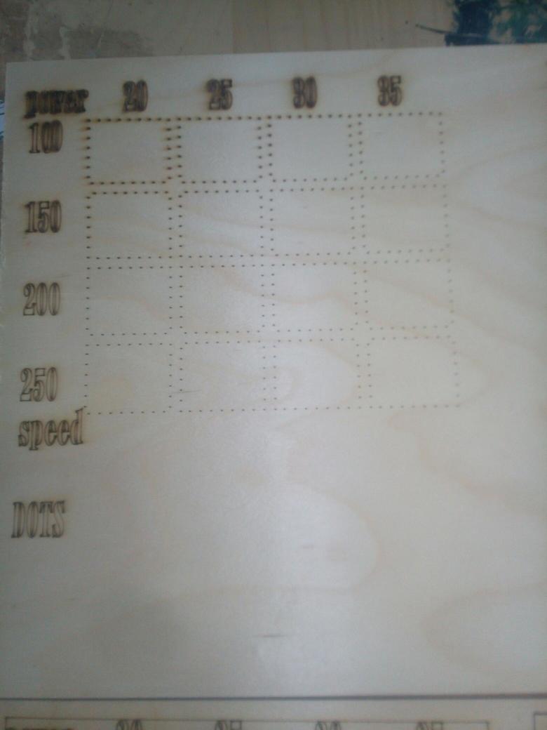
This is a Test for Scan Mode .. Changing Power and Speed..ff
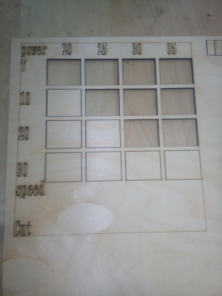
This is a Test for cut Mode .. Changing Power and Speed..
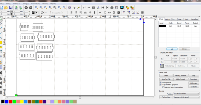
Here Is the how the file looks like .. Adusting Layers for each rectangle to have his special power and speed ..
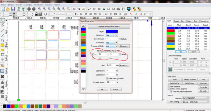
This is How to change Them ..
By testing all those things ..
* Engraving
* Cutting With Low Power
* Cutting with High Power
* Min and Max Power
* KERF in x and Y
This is a Video in arabic how to work with laser Cutter
There are some Parameters you need to take care of when you are working with laser cutter :
1) Focus : Every machine have a focus and this depends on the Lens that collect laser before going on the bed .. In my case The Lens Focal Point was in 6 mm ..
How to know the focus distance between you know from lab manager ?
By sending pulses from different z Levels ..
Until you get the smallest burning point then your focus is ready ..
Funny Fact but it is not safe : I use my finger to adjust the focus ..
2) Power and Speed : This why we are going to make next tests to know how much power and speed to use .. also in normal case the lab manager will provide you with that but it is better if you are going to work a long with the machine to define your parameters with yourself ..The perfect model to work with .. Is to cut with high speed high power to make your work quickly .. Also without burning the back of the working peice .. as you will see at the tests ..
Then let's go through tests ..
Cutting Test
Dot Test
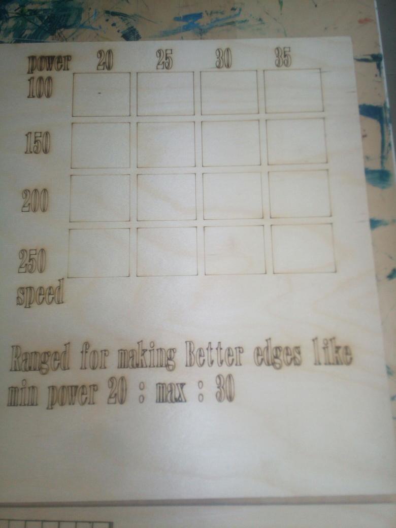
Testing Edges by make a difference between min and max
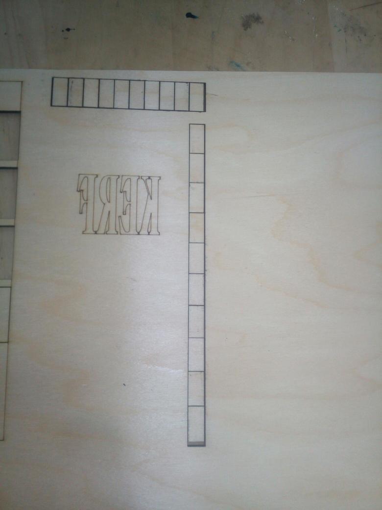
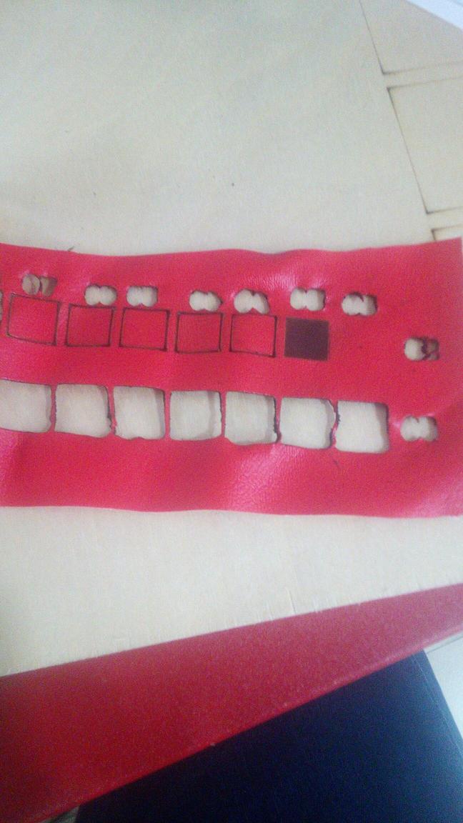
KERF TEST ..
The Idea of KERF TEST .. is to cut 10 recangles each one is 1 * 1 cm ..
then as in the next picture clear .. that there are some thickness from the wood vanished :D ..
So I started to measure it with the verniel ..
I found the disappeared is 1 mm
So the Kerf is 1 mm divided to 10 because it cut 10 Rectangles ..
So it is KERF is 0.1 mm
**Mirrored
Testing Scanning and what is the amount of Engraving I want **Mirrored
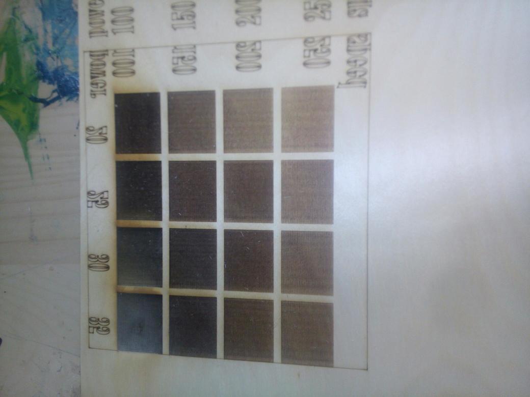
and I made this for wood ..
I made it again for Leather ..
* Engraving
* Cutting with Low Power
* Cutting with High Power
Scan Test
Cut Test
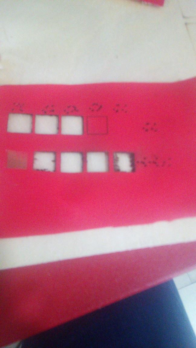
Engraving Using Cuting Mode with low power High Speed

Then I start working on my pressfit design ..
otherwise there was another adventure with kerf concept ..
I tried in the last design I made it was very very wrong and doesnt fit good ..
Kerf in another cad designs is very easy thing to modifiy your cad to work with ..
In OpenScad .. It is another story :)
Like in the last picture and as I said before we are working with cartesien ..
In normal operation with kerf and CAD ..
for outside of the part we add the kerf/2
for the inner sockets we subtract kerf ..
here it is a little bit different ..
each point need justification with kerf ..
so Ii make the center point for my draw and start thinking about how the kerf will change in the equation and finally As in the draw that what i made
** In the Left all points in x diemensions will subtract from them the KERF/2
** In the Right all points in x diemensions will Add to them the KERF/2
** In the Down all points in y diemensions will subtract from them the KERF/2
** In the Up all points in x diemensions will Add to them the KERF/2
Same for the inner sockets ..
After all of this this was ready ..
This is the final code
y=10;// The Y Diemnsion
fit=2.9; // The pressfit Parameter part of X Dimension
width=80; // The width of the Plate part of X Dimension
x0=0;//Postion for the whole plate for x
y0=0;//Position for the whole plate for y
kerf = 0.1;
standard_piece=[
[x0 -kerf/2,y0+y-kerf/2],
[x0-kerf/2 ,    y0+kerf/2+y*2],
[fit+x0-kerf/2, kerf/2+y0+y*2],
[ fit+x0-kerf/2, kerf/2+y0+y*3],
[ fit+x0+width+kerf/2,kerf/2 +y0+y*3],
[ fit+x0+width+kerf/2, kerf/2+y0+y*2],
[ 2*fit+x0+width+kerf/2,kerf/2 +y0+y*2],
[ 2*fit+x0+width+kerf/2, y-kerf/2+y0],
[fit+x0+width+kerf/2, y-kerf/2+y0],
[fit+x0+width+kerf/2, y0-kerf/2],
[ fit+x0-kerf/2, +y0-kerf/2],
[ fit+x0-kerf/2,   +y+y0-kerf/2]];

fit_left=[[x0,y0+y],[x0,y0+y*2],[fit+x0,y0+y*2],[fit+x0,y+y0]];
//fit_right=
 num = 5 ; // Number of sockets you want to make inside this plate
 x = 1;  // Which sockets do you want to make from left to right
 cutpiecex=((2*fit+width+x0)/num)*x;
 cutpiecey=(y0+3*y)/2;


 projection()
difference(){
    color("Magenta",0.5)


 linear_extrude(height = 10, center = true, convexity = 100, twist = 0,$fn = 100)
 {
 //    translate([20,0, 0])

 polygon(standard_piece);
 }

linear_extrude(height = 10, center = true, convexity = 100, twist = 0,$fn = 100)
 {
 for (x =[1:5]){
      num = 6 ; // Number of sockets you want to make inside this plate
  // Which sockets do you want to make from left to right
 cutpiecex=((2*fit+width+x0)/num)*x;
 cutpiecey=(y0+3*y)/2;

cut_piece = [
     [cutpiecex-(fit/2)+kerf/2,cutpiecey-(y/2)+kerf/2],
     [cutpiecex+(fit/2)-kerf/2,cutpiecey-(y/2)+kerf/2],
     [cutpiecex+(fit/2)-kerf/2,cutpiecey+(y/2)-kerf/2],
     [cutpiecex-(fit/2)+kerf/2,cutpiecey+(y/2)-kerf/2]];

echo ("         outside    ", ((2*fit+width+x0)/num)*x,"   ", (y0+3*y)/2 );
 polygon(cut_piece);

 }

 }}
after understanding the idea of KERF in Cartisien way ..
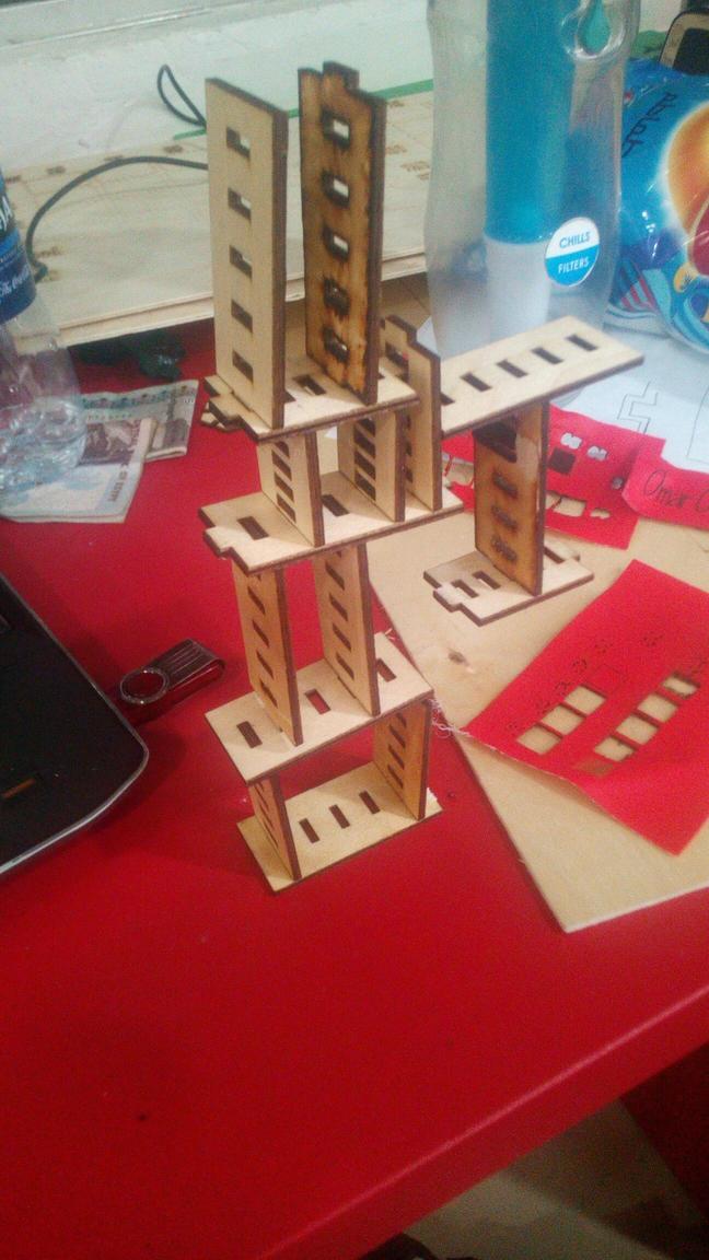
I tried on the machine and it works great ..
This is my Model I made from my Pieces .. It is like a Vraiable Building Blocks that you can use to build any thing in 2 Dimensions
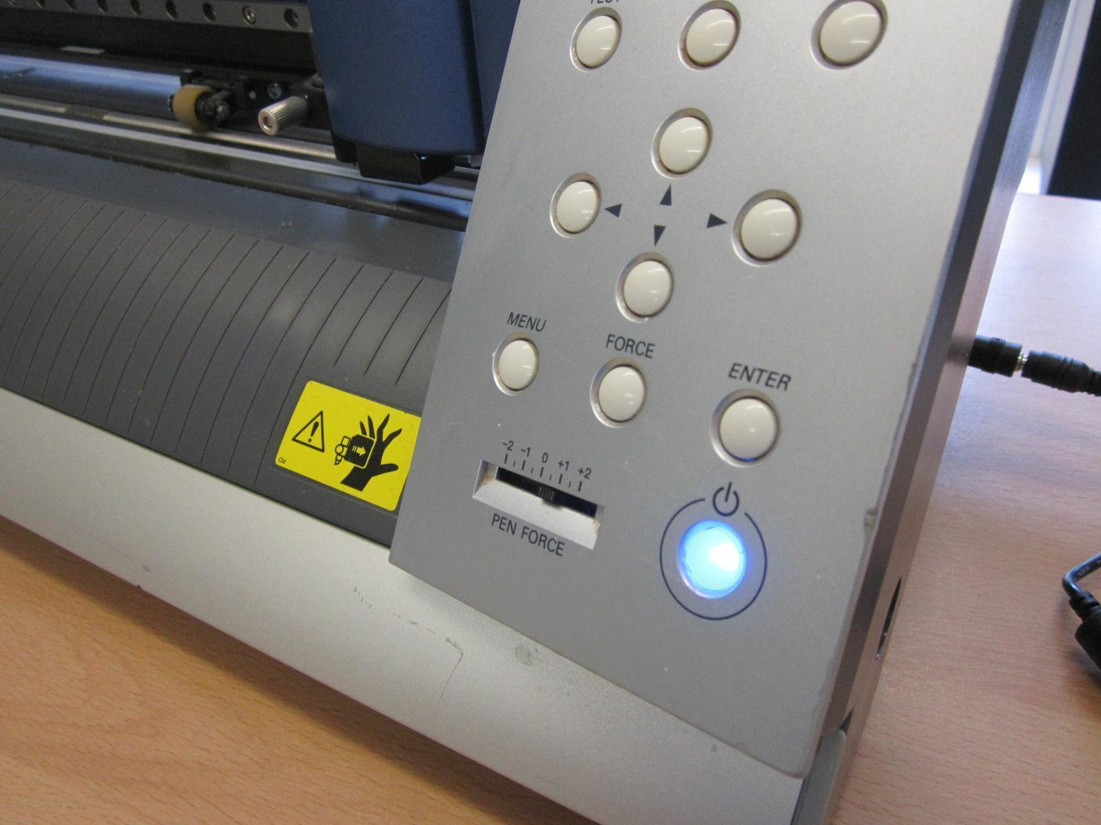
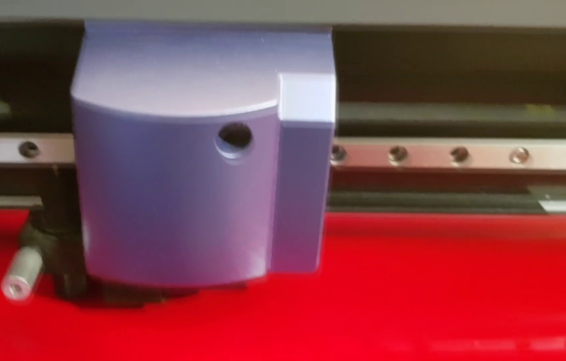
Then I started with the Viynl cutter .. The Machine I am Going to WOrk on is Roland GX-24 Vinyl cutter .
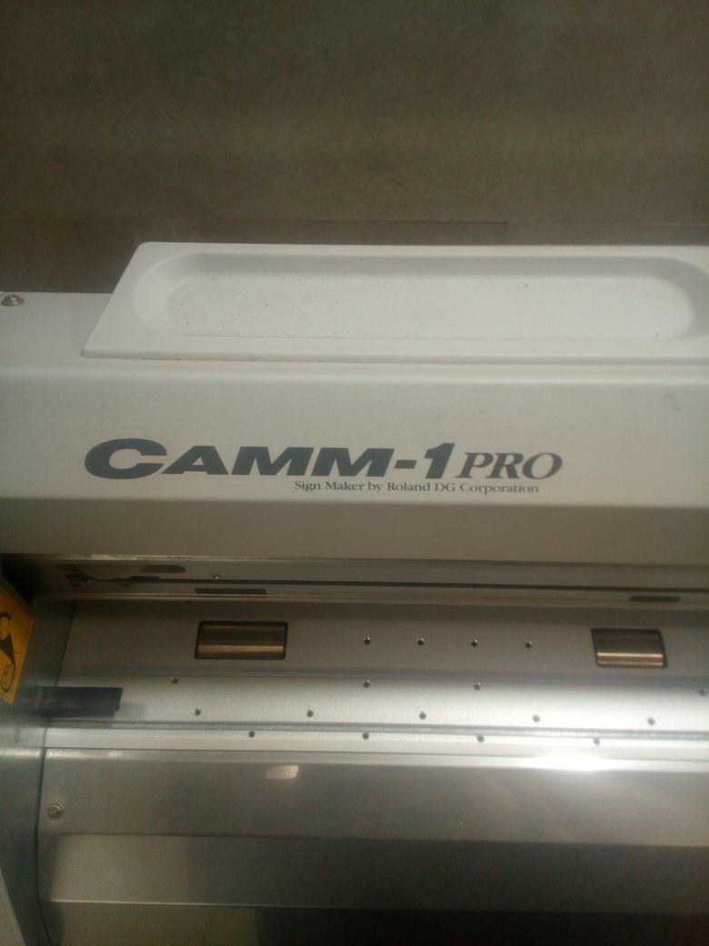
This is Machine Parts .. To understand how it works ..
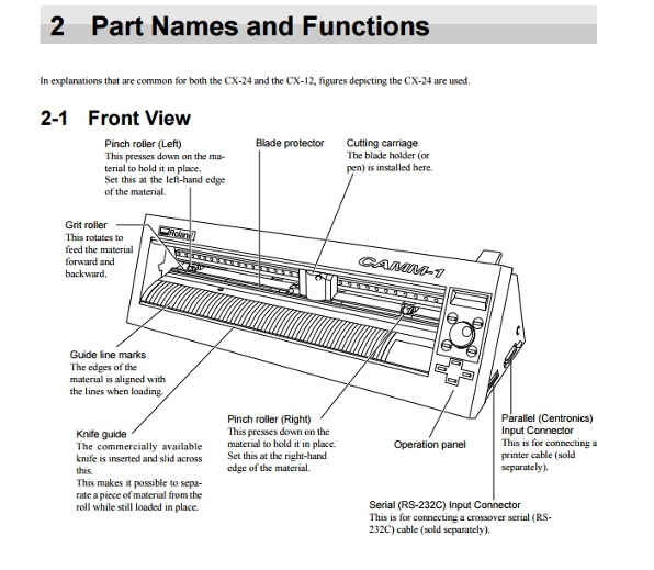
I found this Tutorial About How to Deal with the Machine ..
Check out this link Here
After Checking the Link You need to Take Care of :
1) The machine only works if the wheels are placed within the white markers.
2) Which option you choose from the menu depends on what material you are loading.
Roll is for setting up the starting point manually.
Piece is for letting the machine measure all sides of your loaded sheet. (like with smaller 'leftover' pieces)
Edge is for letting the machine only find only 1 side of your loaded material. (when you just want to find the starting point at the edge of your material.)
For My Case I used Piece :)
Start Selecting the Picture
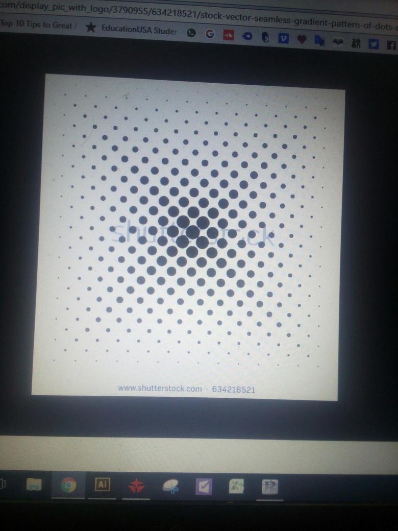
Import it to the Cut Studio and get the outline of the picture
Import Picture and Get Outline ..
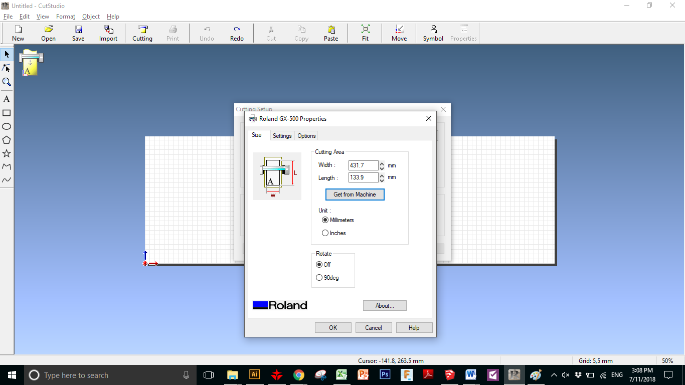
Connect to the machine and get the size of the piece i will work on ..
start cutting the piece
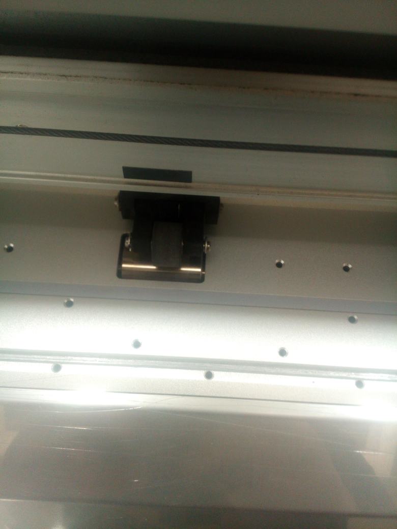
In next 2 Pictures you will fix the Piece you are going to use in those rollers at least 2 of them ..

This is How interface looks like
After Reading my piece Dimensions I am going to work with ..
after putting it on my labtop ..
This Another Going though another Design ..
# For Better Documentation
I made another Going through the machine ..
First We fix the piece on the Machine ..
Those are Rollers on the Machine For fixing on our sheets on the machine ..
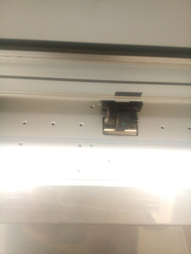
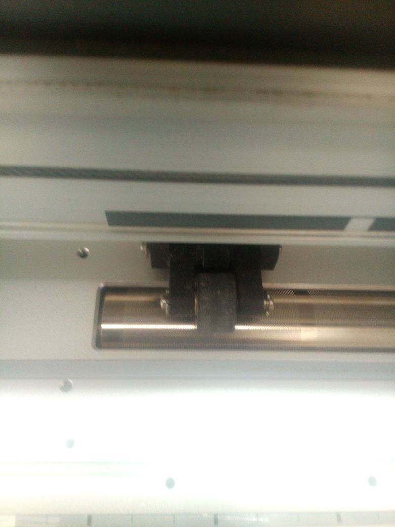
To Fix the Sheets The working Area between 2 or Three Rollers
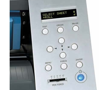
then as i said above .. There are 3 Settings .. Piece , Sheet , Edge ..
Then I used Piece
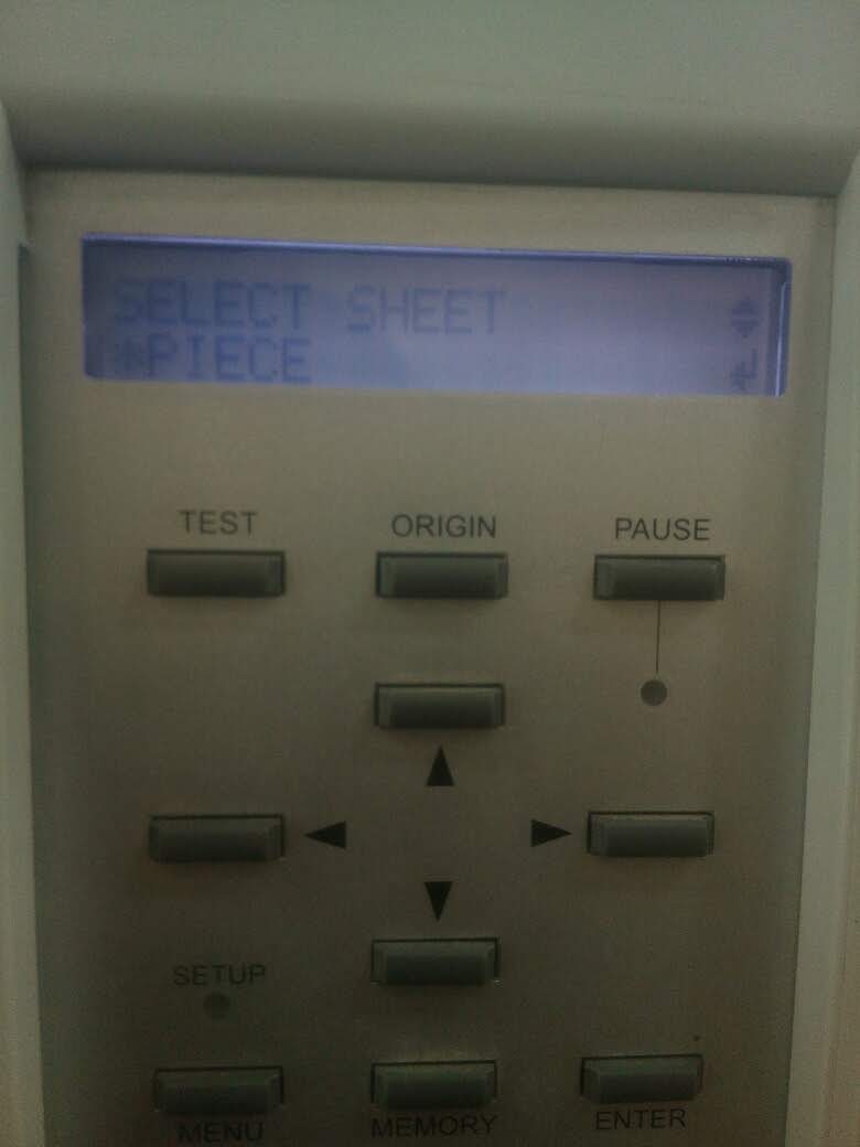
You select Piece from Mode and this is the interface ..
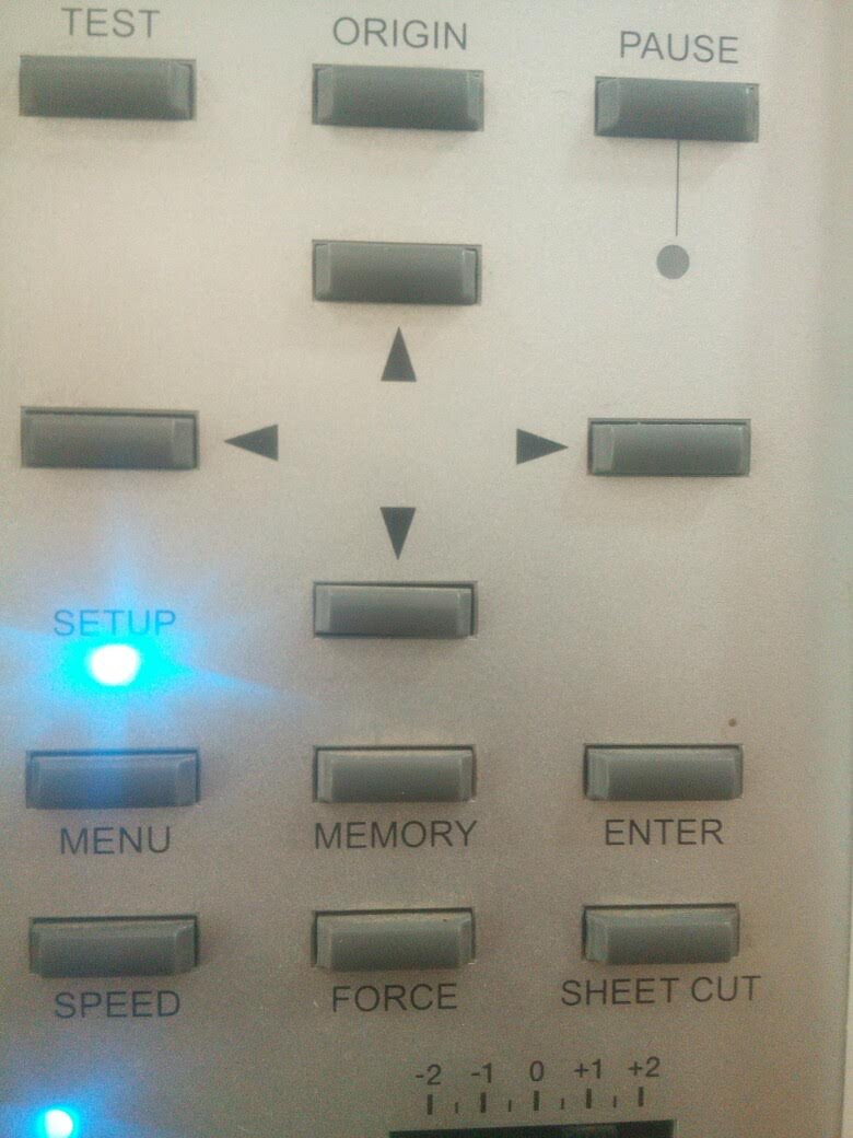
after selecting piece we give Enter
This is video for the process
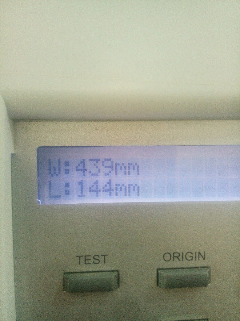
and This is the Dimensions after I made piece ..
Then We open the software Cut Studio..
First we start reading the dimensions of the Piece we are going to work on ..
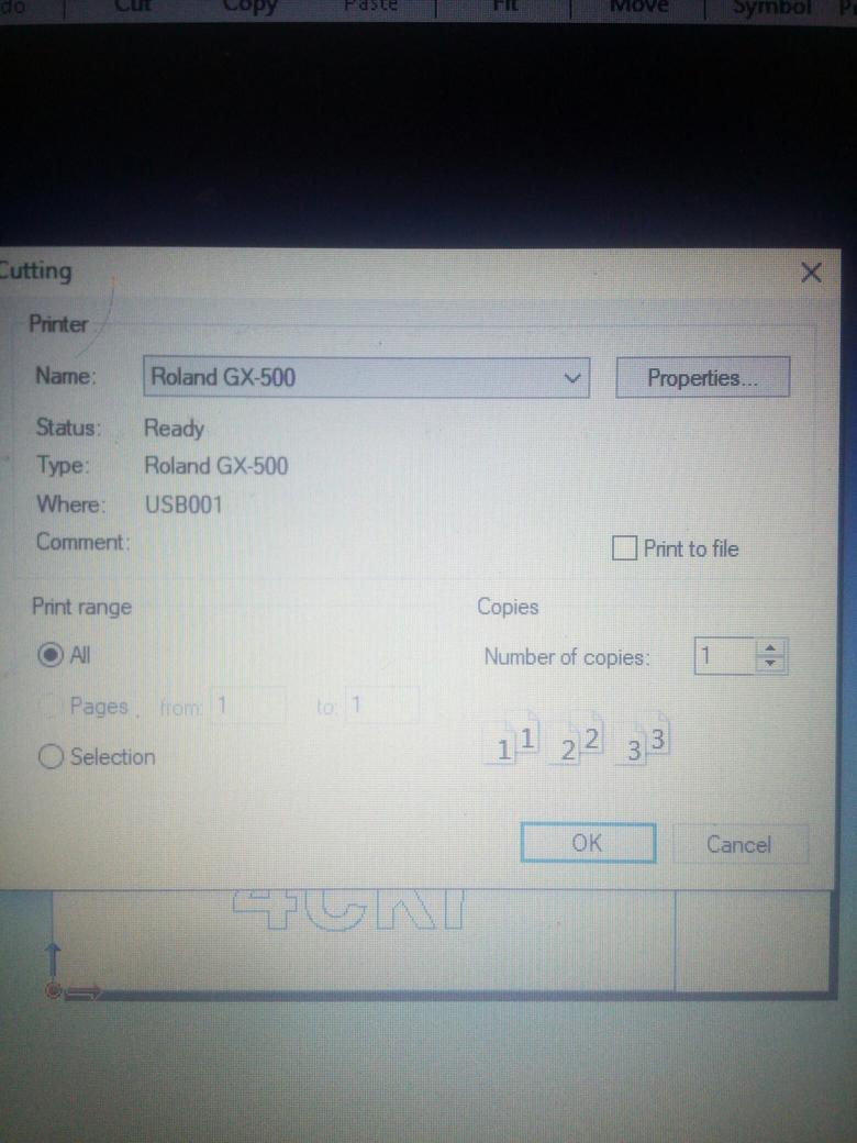
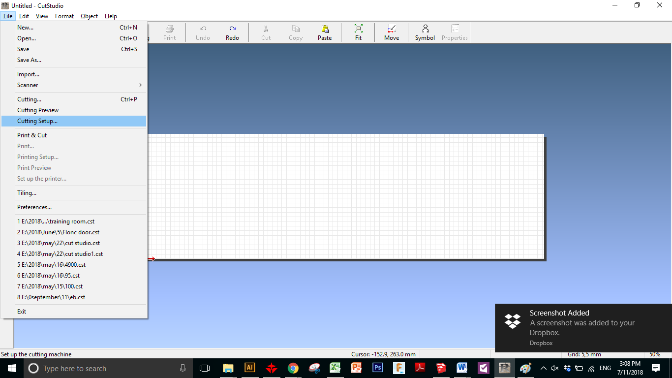
#The Software Cut Studio
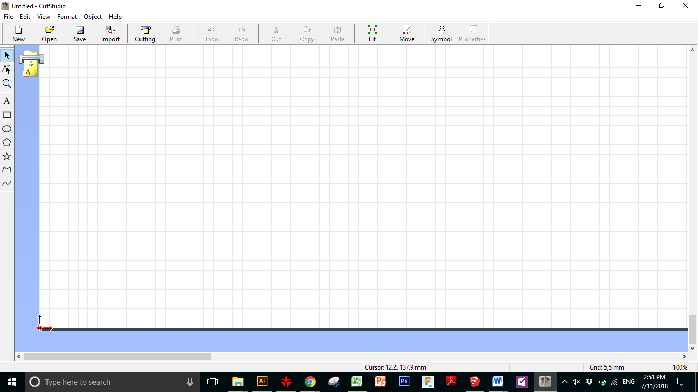
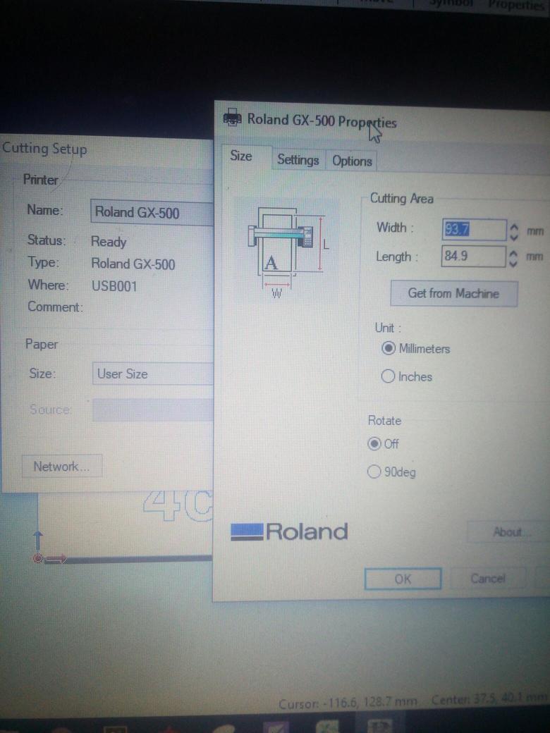
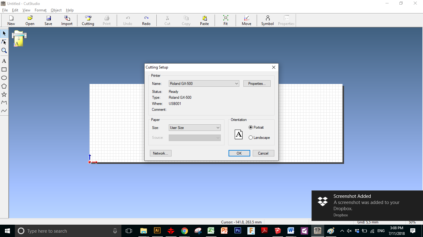
Then Select Cutting Setup
Then Properities
Get from Machine
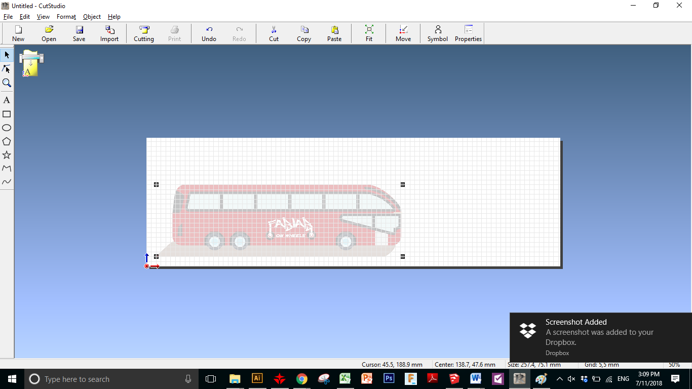
Then Import ..
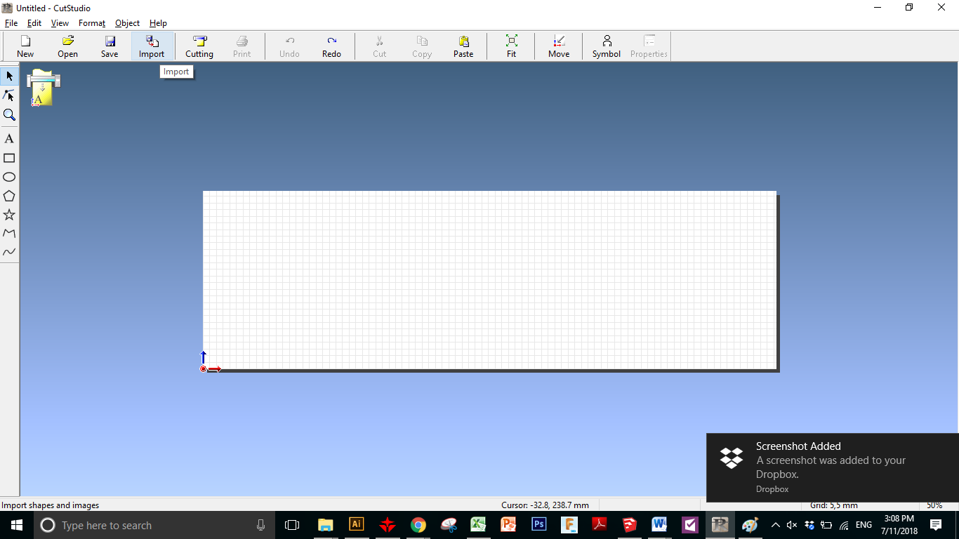
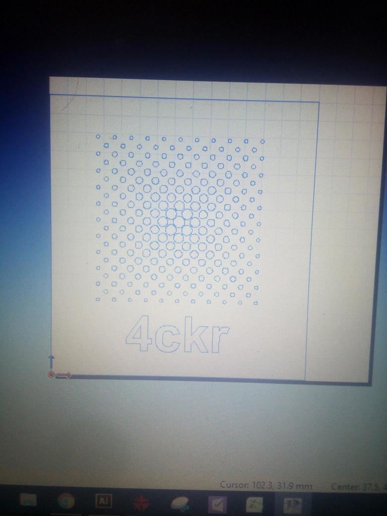
And this is the design ..
Then Right Click and Select Image Outline ..
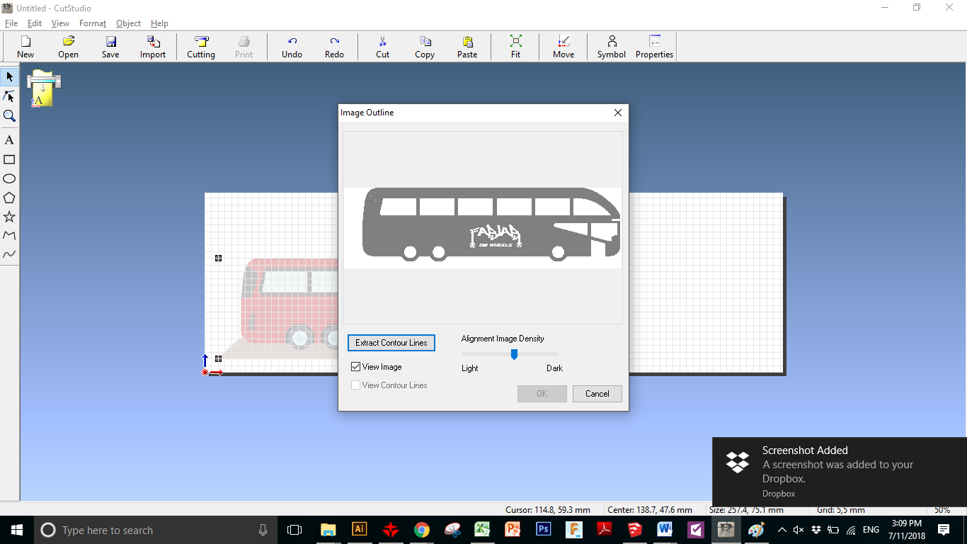
Select the Extract Image Countour
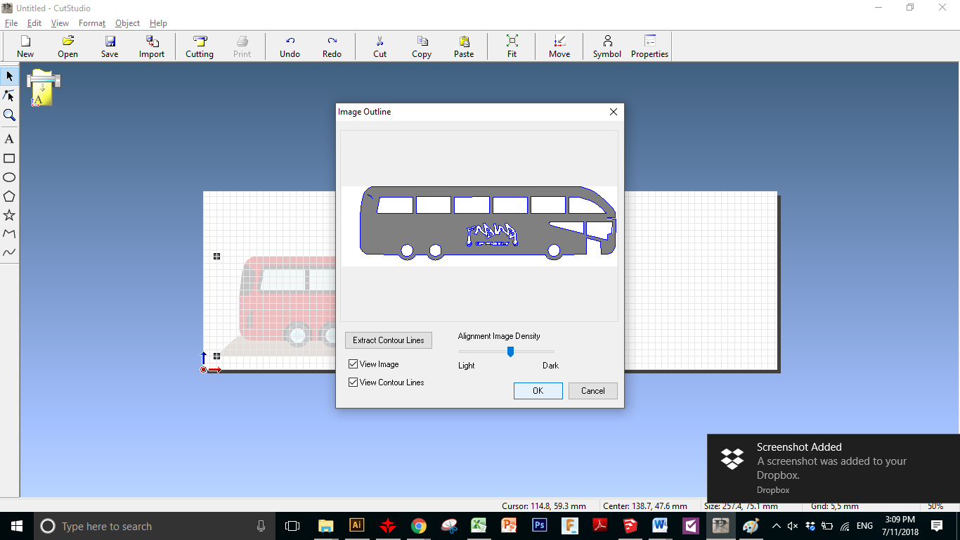
This is how it is going to liiks like ..
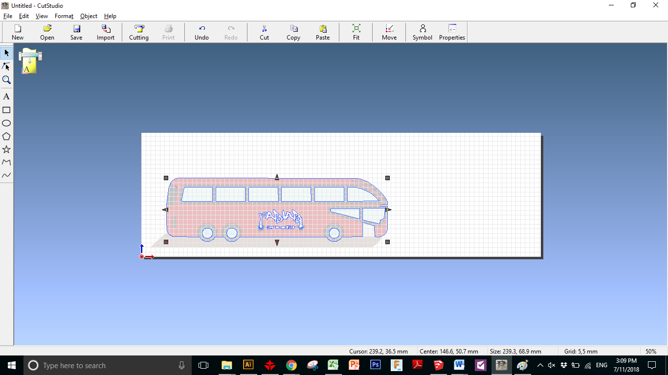
Then From File we select Cutting Preview ..
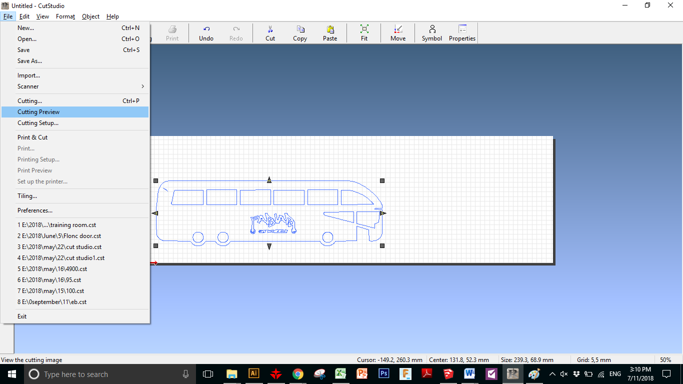
THis is the Preview Screen
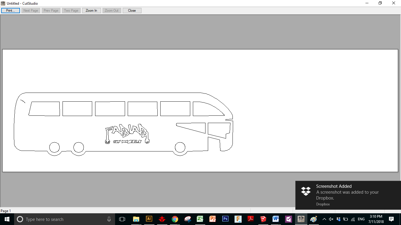
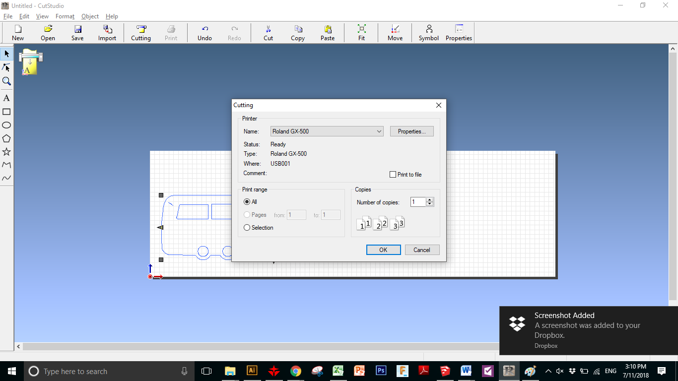
Then we cut it
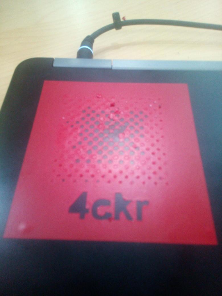
and this is the Output ..
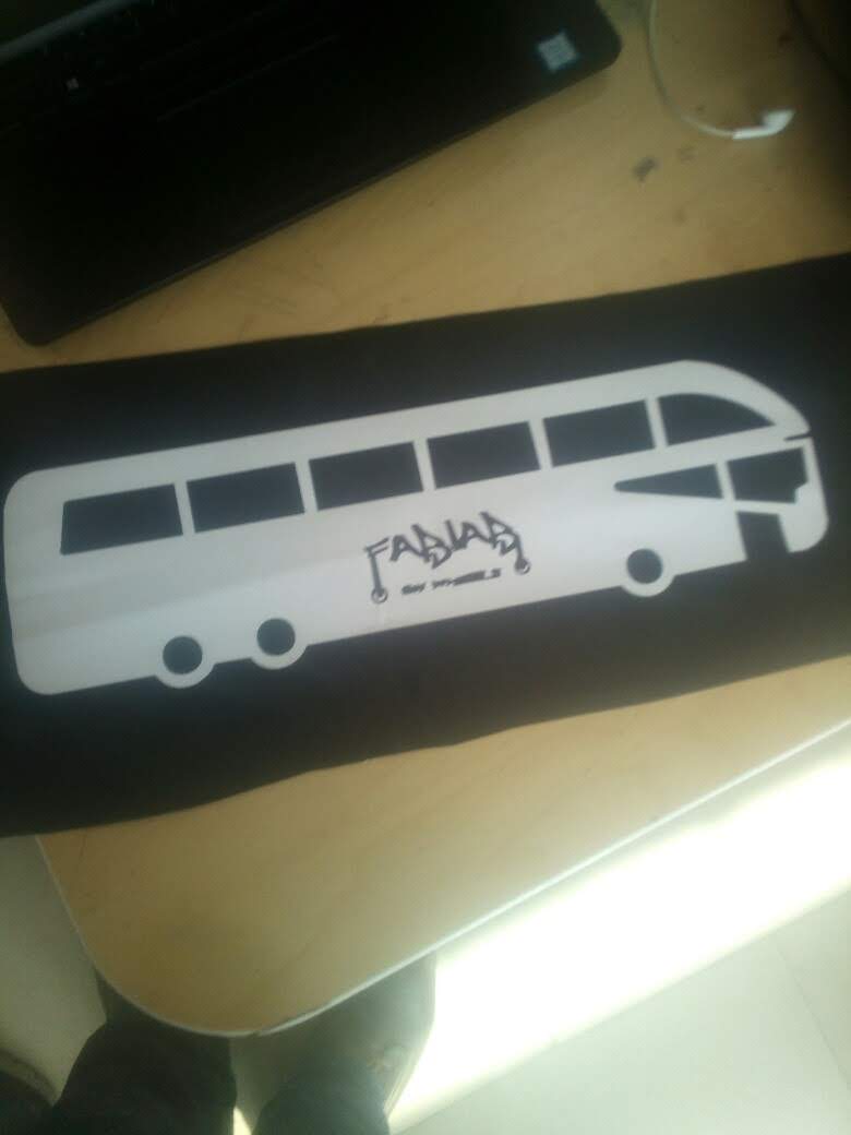

and this is my design Logo for the Project I am responsible for Fab Lab On Wheels
Then For Final Project ..
I need to make a quick box with pressfit ..
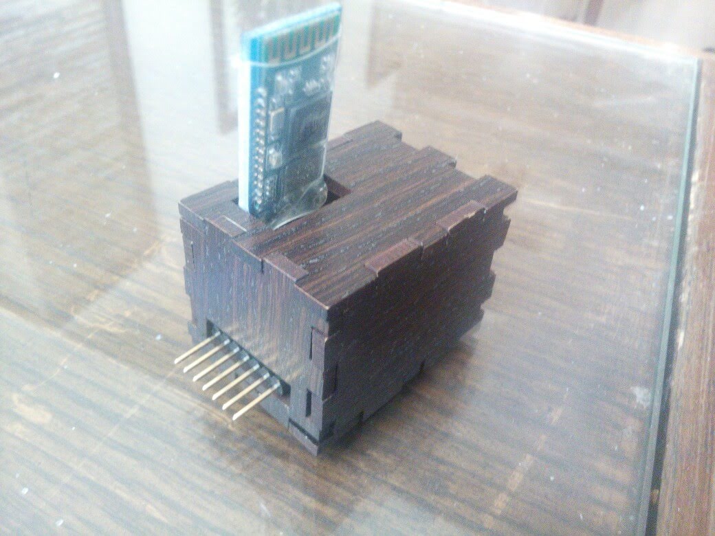
so I Used Makercase to make it .. And I then I Edited it to make fit with my Electronics Board design ..
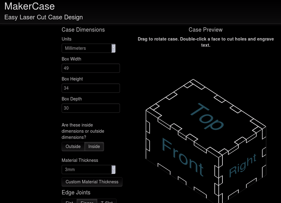
and this is the box :D
This is the FIle of the design ..