Electronics ProductionTarget >>
group assignment:
characterize the specifications of your PCB production process
individual assignment:
make an in-circuit programmer by milling the PCB,
then optionally trying other processes
Assignment 5
So first for the Group Assignment ..
Out instructor suggest to change the parameters of Offests in the FabModules ..
So we did different PCBS .. I made the 4 Offests one ..
So lets start with how to work with the machine ..
CNC milling machine have a very dificult operation process ..
You start with Getting your machine ready by this process ..
- First Choose a good PCB Sheet to work with ..
- you start with cleaning the surface of the Sheet by washing it with cleaner ..
- then we double tape the Sheet with the bed of the machine ..
- Then you start with knowing what are the type of Endmills .. We use the 1/64 for making our traces and we use the 1/32 to cut the border of the circuit
- Then After you know how you are going to change tools
- We Start will go through learning what is fabmodules Will come in next part in documentation
- MDX20 is good with communicating with the Fabmodules serial not in need to export RML files
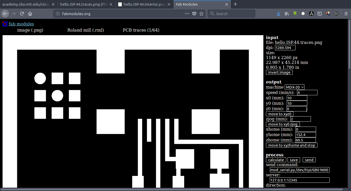
- Then we start seting x,y,z
- Then we start run the files
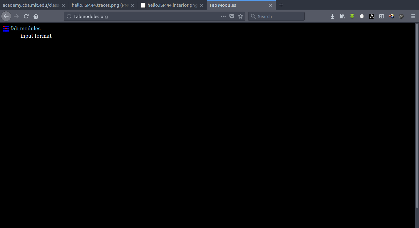
Not let's start with the Fab Modules ..
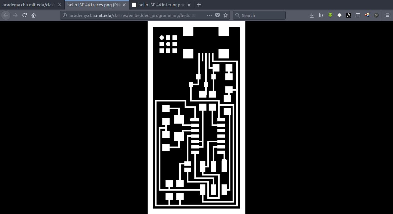
First download from fab academy the 2 PCB ..
#Traces
#Outline
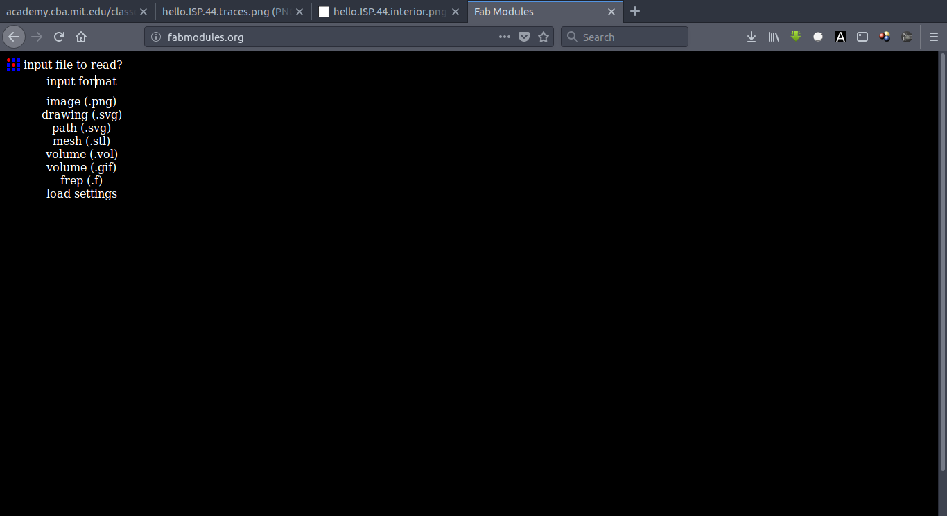
Then Open Fab Modules ..
And we use Fabmodules as a CAM Program that will help to translate our design from Picture To GCode to Work with ..
Then Select images and select my image
Then Select Roland Mill
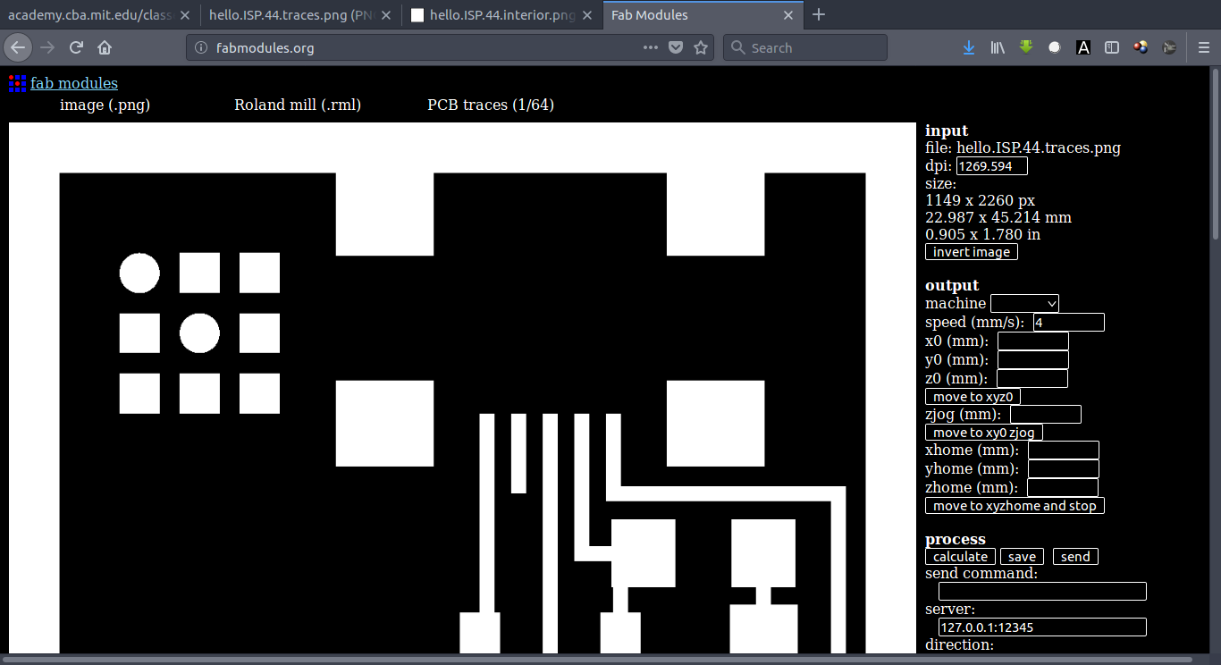
Here there are 2 selection ..
For the Traces we use 1/64 Traces
For the holes we use Outline
Like reducing the speed of the machine and how many offsets you can make ..
The Numbers was better for me ..
I worked on 2 mm/s as a Speed for the machine and Make 4 Offsets as this is make the bit safe but on sametime there is not a short circuits for any reason
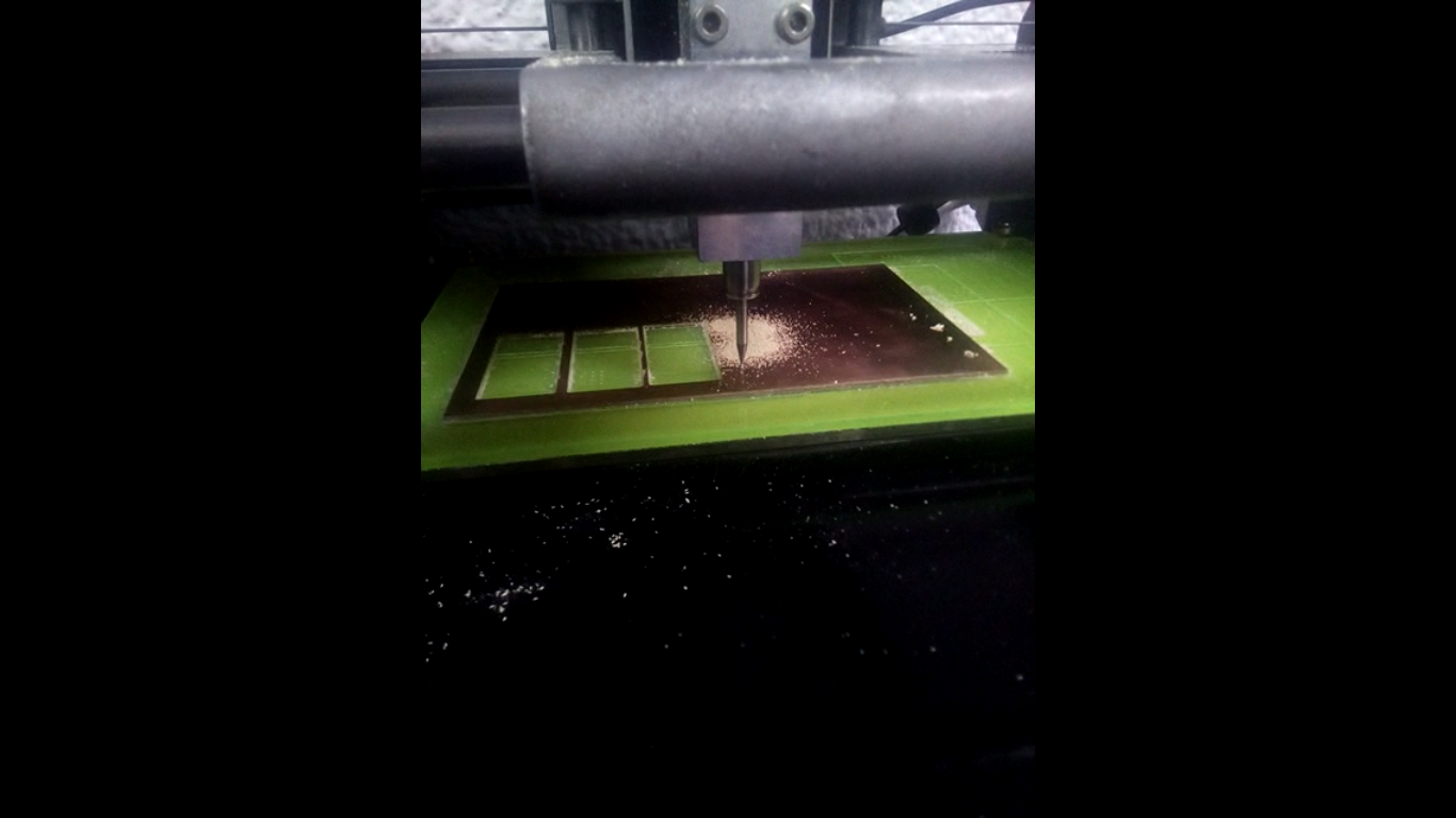
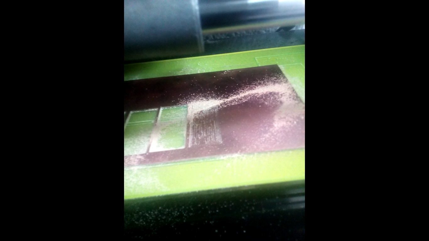
Then Run :) and PCB is ready ..
This is Machining .. An Important note .. Be sure that the Double tape you are using a Very thin .. To make sure that the PCB is leveled .. Also Use FR1 as it is more easily to machine it and More healthy than FR4 ..
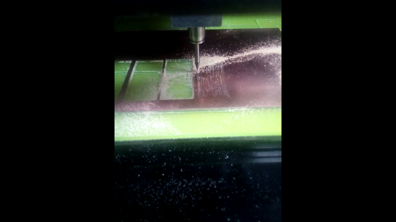
Finished :D
This was the easy part indeed Then I start with soldering and I am wearing glasses :) and I was not clear to see the component good ..
The Tools I used was ..
Tweezers
Hot Air
Soldering Iron
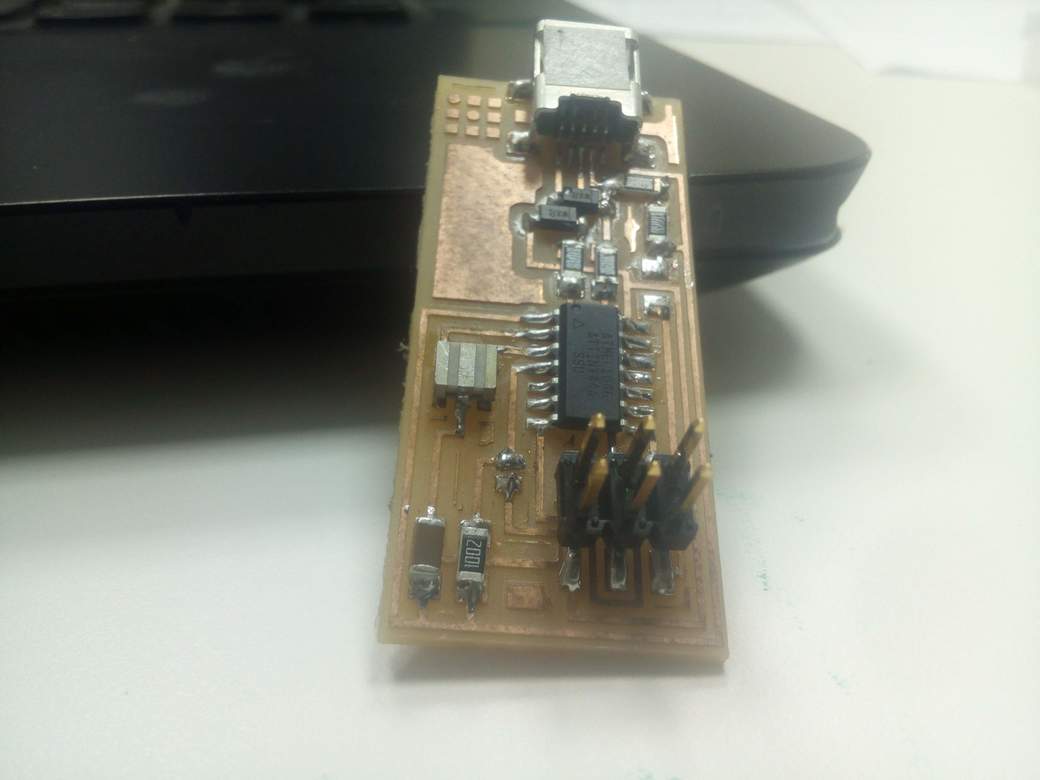
Then I was very Happy After I finished it ..
Now I will go through the Programming It .. As I followed FabAcademy Tutorials
For Progamming The ISP and This is what I have Done ..
After Editing the Makerfile as in the Tutorial ..
And these are all Order you are going to use in the Terminal..
cd ~/Desktop
wget http://academy.cba.mit.edu/classes/embedded_programming/firmware.zip
unzip firmware.zip
cd Desktop/firmware
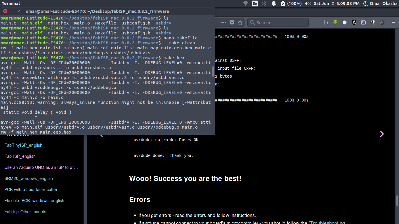
make clean
make hex
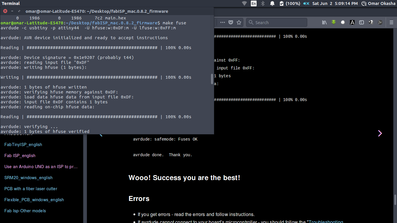
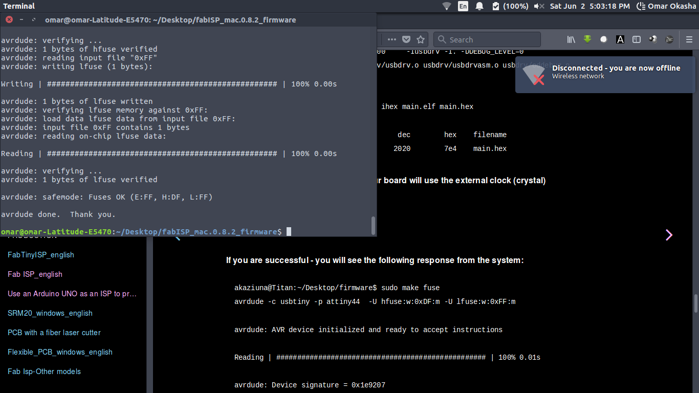
make fuse
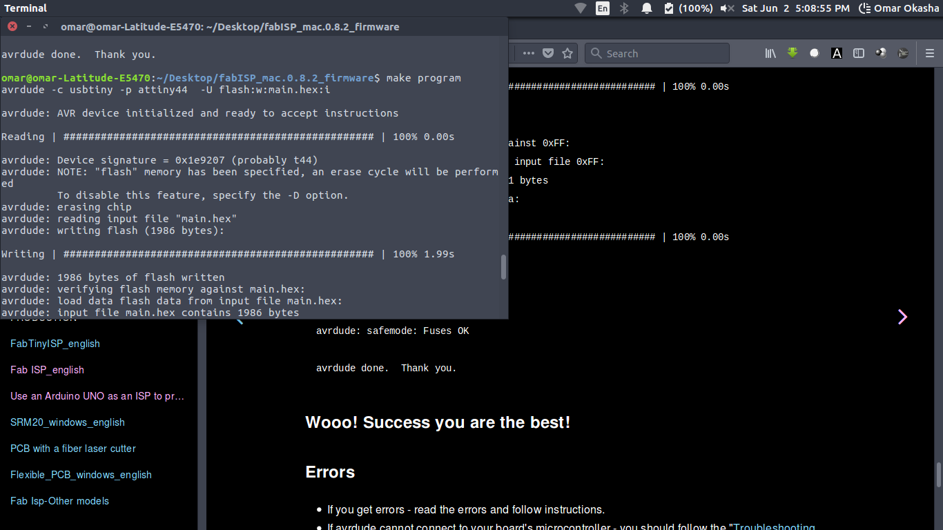
make program
Make clean
Make Hex
Make Fuse
Make Fuse
make Program
As I am now finished the Assignment ..
My Experiences and Notes My Experience was a very hard with Soldering ..
I spent 2 Weeks In soldering and I made 3 Fabisps and Damaged them all because I Have some Issues with Soldering .. Like :
1) My Hand is shaking a lot ..
2) I cant see Component
3) I cant focus from the Enviroment I am working at because of the Tempreture Degree
4) The Idea of I have to catch the component with hand and Iron with Otherhand and the Solder with what ..
As a Final Experience with this ..
I working Under Air Conditioner With my Mobile Flash Focused On components and Boards ..
I put on 1 Pads for all Components a Solder bubble ..
I have a Straight Gift which is strong One To can Work WIth ..
And I used Hot Air To put component after this .. I finished PCB in 15 to 30 Minutes ..
And to show How I understand the Process In this Assignment Craig My Global Evaluator .. Suggest Answering those ..
Q) how do you get the design from the PC to the mill?
The Machine in the Lab Was already Interfaced with Fabmodules through Python Code working Loncally on the Desktop for the machine
Q) What cutter did you use and why?
We use MDx20 With Bits 1/64 and 1/32 for 2 Reasons that the Machine in the Lab and Easily to communicate with it through fab modules .. As I worked before with MonoFab and MDx40 .. The different we use the interface with the machine that called VPanel and You going to need to download from fabmodules RML Files and Use it to with VPanel ..
Q) How do you set up the mill to ensure your design is cut correctly?
You must have a very thin Double tape to ensure that the PCB is leveled and that for the Adusting the Z .. You move the z almost above the PCB with like 1 cm then you let the bit to lay down on the PCB and you tight it again and start working ..
Q) What is the process you followed to populate your board with components?How did you know which ones to use? What did you have to pay attention too?
I mentioned this with my Experience as this is was a main issue with me
Q) How did you test your board and upload code to it? How do you know if it worked or not?
I checked the Short Circuit test using the Multimeter