Electronics Design Eagle
Assignment 7
So This assignment is to do :
group project:
use the test equipment in your lab to observe the operation of a microcontroller circuit board
individual project:
redraw the echo hello-world board, add (at least) a button and LED (with current-limiting resistor)
check the design rules, make it, and test it
extra credit: simulate its operation
extra credit: render it
So I will First I will Show How to use eagle .. I have already a Video on youtube that Illustrate how to make a PCB from Eagle Passing By Gimp and Fabmodules .. for 35 Mins
First This the GUI OF Eagle
and there are two things you can do on eagle
1) Schematic
2) Board


After Selecting Schematic We start Using this is the GUI That you will Use ..

To change the Back Ground To Black We use " User Interface "

Then we make background Black for Schematic

And Our Orders are
1) Jun for J
2) Mov for M
3) Wire for W
4) Del for D
5) Add for A


Here we try the Console orders like typing " add "

This is the GUI For add

This is how to search .. like if we are searching for 2n2222 and we type 2n222 the program will not understand .. you must write 2n2222
Check other examples ..


By click add this is how it looks like in the schematic you start clicking every where to add the component you want ..

This is after adding all the components

Then we start adding to all ends of the components Juncation .. So why Junctions .. To Ensure when you use wires that your wire is connected ..

This is after all componets are connected with Juncations

This is after using " Wire " order .. after that you have finshed your Schematic
if you checked the mouse you will find that the mouse stop at a Button that can Transfer that Board from Schmatic to Board ..

Push YES :D


Let's Start Assign Our Shortcuts .. We here works with :
1)ROU
2)RIP
3)MOV


We start here moving and sorting our objects

For more advanced details before working you can make your design rules like clearance distance between Wires , Pads and Vias ..

We here start "Route" Order ..


We Hre use the grid to make our Board from Inch Scale to MM Scale ..


Then we start Routing the Circuit

For Double Layer .. You can select if your wire is top or down ..

After Finishing Wiring ..


For Tracks : We use Bottom , Pads , Vias , Dimensions
For Holes : We use pads , Vias , Dimensions


here we start using GIMP ..

Starting with Open

Selecting our files


Selecting each Photo and from Image >> Canvas size >> we Start Increasing Each photo with 20 Pixel .. ANd make it Center


then We start Flatten Each Image .. To fill every empty places with White ..

For next Screens >> The cnc machine Works like this >>
For Tracing >> It move on the Difference between the Black and White ..
For Holes and Cutting Edges >> It move on Black


Here we start using Fab Modules to finalize by adding pictures >>
Selectring Roland Mill
Select for Traces >> PCB Traces 1/64
Select for Holes >> PCB OUTLINE


Start selecting the machine and The Values for the pcb depending on your machine


After Saving you will have the Files for your cnc ..

Here we start Design the Assignment ..
Here we start Design the Assignment ..Import Libraries ..

Then You can see Them in the Add Pop Up
Start Adding Components
Start Adding Components
Here start Searching for DRC File For Fab Academy

Finish Designing the Schematic
Check the design
Check the design
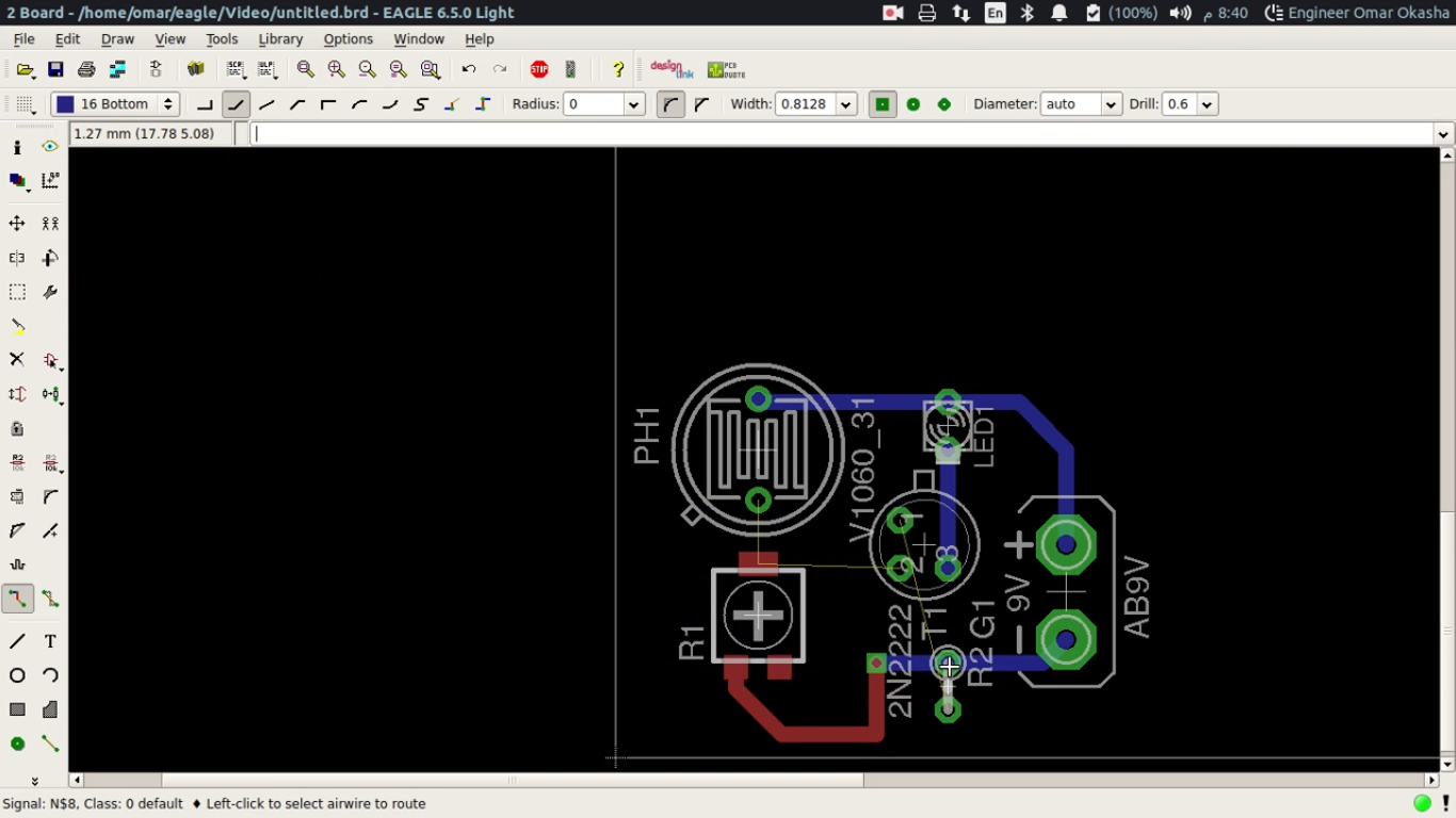
Start the Routing Design
Start Routing

Start Routing
Finish the Design
Start Implementing as in the Electronics Production
Start Implementing as in the Electronics Production
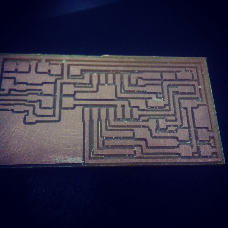
After Machining ..
I made a New design after my first design was damaged .. because of I have an issue was soldering and cant figure out until then how to make good solder and I damaged it with hot air ..
That is my new design ..


And these are the files for machining

This is the final board after finishing

This is The Rendering Phase

Then I exported it from Eagle as IDF to can use it as 3D model in Freecad ..
And that is the rendering of the circuit ..

Programming Phase :
The code I worked with ..
Arduino Code :
void setup() {
  // put your setup code here, to run once:
  pinMode(PA3, INPUT);
  pinMode(PA7, OUTPUT);


delay(5000);

}

void loop() {

  // put your main code here, to run repeatedly:
if(digitalRead(PA3))
{
digitalWrite(PA7,HIGH);
delay(1000);
digitalWrite(PA7,LOW);
delay(1000);
digitalWrite(PA7,HIGH);
delay(1000);


digitalWrite(PA7,LOW);
delay(1000);
digitalWrite(PA7,HIGH);
delay(1000);


digitalWrite(PA7,LOW);
delay(1000);
digitalWrite(PA7,HIGH);
delay(1000);

}


}
AVR Code
#include <avr/io.h>
#include <util/delay.h>


int main (void)
{
  // set PA7 to be output
  // set PA3 to be Input
  DDRA = 0b10000000;


  while (1) {
    if (!(PINA & 0b00001000))
    // Read pin 7

{

    // set PA3 high
    PORTA = 0b10000000;
    _delay_ms(20);
    // set PA3 low
    PORTA = 0b00000000;
    _delay_ms(20);


    // set PA3 high
    PORTA = 0b10000000;
    _delay_ms(200);
    // set PA3 low
    PORTA = 0b00000000;
    _delay_ms(200);
  }
  }
  return 1;
}
Here is the Testing Phase : This is The Board Working :)
Enhancing my skills :D :
Some Ideas For PCB Fabrications ..
Idea Number #1
Idea story :
I have been working on an idea for a attiny shields pcbs that can replace any one of them with another one ..
Advantages :
If you have 1 Attiny and need to use it on some different projects with different pcbs ..
If there are a Courpted component .. or PCB damaged .. you can change it easily
Predicted Disadvantages :
The Noise may be disturbing because of the junctions ..
So Lets Design ..
I designed 3 Boards For Hello Echo ..
1) Attiny 44
2) Main Board component
3) LED and Pushbutton
Note :
Each circuit have it is Dimensions to can fit with each others ..
This is the 3 Designs ..
This is the Inspiration
Sparkfun Link to the Photo

The Attiny 44
BOM :
1) Attiny 44
2) 2 Pin headers Female


The Main Board :
BOM :
1) Oscillators
2) 2 Pin headers Female
3) 2 Pin headers Male
4) Res 10k
5) Cap 1u
6) ISP Header
7) FTDI Pins


The Hello Echo
BOM :
1) Push Button
2) LED
3) Res 499
4) Res 10K


Last note :
This Idea Comes really from the amount of component and PCB I courpted
If you dont have a background about electronics ..
There are basics elements you need to learn to go through electronics ..
1) Voltage : Voltage is the pressure from an electrical circuit’s power source that pushes charged electrons (current) through a conducting loop, enabling them to do work such as illuminating a light.
Quote from here
2) Current : An electric current is a flow of electric charge. In electric circuits this charge is often carried by moving electrons in a wire. It can also be carried by ions in an electrolyte, or by both ions and electrons such as in an ionised gas (plasma).
Quote from Wikipedia
3) Ohms Law : Ohm’s Law is a formula used to calculate the relationship between voltage, current and resistance in an electrical circuit.
Quote from here
4) Resistance : Resistance is the opposition that a substance offers to the flow of electric current. ... In general, when the applied voltage is held constant, the current in a direct-current (DC) electrical circuit is inversely proportional to the resistance.
Quote from here
5) Capacitance : a device used to store an electric charge, consisting of one or more pairs of conductors separated by an insulator.
Quote from here
6) Inductance : the property of an electric conductor or circuit that causes an electromotive force to be generated by a change in the current flowing. "the inductance of the winding"
Quote from here
7) Relay : an electrical device, typically incorporating an electromagnet, which is activated by a current or signal in one circuit to open or close another circuit.
Quote from here
8) Transistor : a semiconductor device with three connections, capable of amplification in addition to rectification.
Quote from here
9) Diode : a semiconductor device with two terminals, typically allowing the flow of current in one direction only.
Quote from here
10) Zener Diode : a form of semiconductor diode in which at a critical reverse voltage a large reverse current can flow. Origin 1950s: named after Clarence M. Zener (1905–93), American physicist.
Quote from here
11) Pin Header : A pin header (often abbreviated as PH, or simply header) is a form of electrical connector. It consists of one or more rows of male pins typically spaced 2.54 millimetres (0.1 in) apart, but common sizes also include 5.08 millimetres (0.2 in), 5.00 millimetres (0.197 in), 3.96 millimetres (0.156 in), 2.00 millimetres (0.079 in), 1.27 millimetres (0.05 in) and 1.00 millimetre (0.04 in).
Quote from here
12) Breadboard : a board for making an experimental model of an electric circuit.
Quote from here
13) Microcontrollers : is a small computer on a single integrated circuit. In modern terminology, it is similar to, but less sophisticated than, a system on a chip or SoC; an SoC may include a microcontroller as one of its components
Quote from here
14) Arduino : Arduino is an open-source electronics platform based on easy-to-use hardware and software. Arduino boards are able to read inputs - light on a sensor, a finger on a button, or a Twitter message - and turn it into an output - activating a motor, turning on an LED, publishing something online. You can tell your board what to do by sending a set of instructions to the microcontroller on the board. To do so you use the Arduino programming language (based on Wiring), and the Arduino Software (IDE), based on Processing.
Quote from here
15) Sensors : a device which detects or measures a physical property and records, indicates, or otherwise responds to it.
Quote from here
16) Actuators :An actuator is a component of a machine that is responsible for moving and controlling a mechanism or system, for example by opening a valve. In simple terms, it is a "mover".
Quote from here
to understand More ..
Check this link for Understanding the Concpet of Electricity and Electronics ..
Check this link - Electronics Concepts
Check this link for Illustarting the basic components ..
Check this link - Basic Component
Check this link for examples of circuits and it is Simulations ..
Check this link - Falstad