Assignment
- group assignment:
review the safety data sheets for each of your molding and casting materials,
then make and compare tests with each of them
individual assignment:
design a 3D mold around the stock and tooling that you’ll be using,
machine it, and use it to cast parts
Acknoledgements
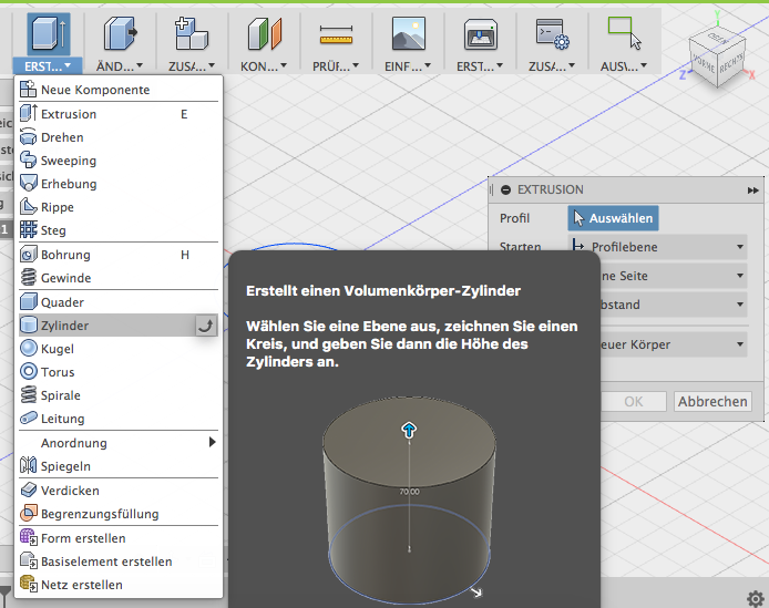
- Originally I wanted to use Solidworks because they provided us with a interface to othermill, which we use here. But since I had a fellow student how was already conversant in these technologies with Fusion 360 and due to the tight time constraints, I decided to try out Fusion 360.
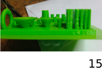
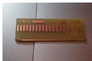
- My idea is to keep the mold simple as possible. I saw how my fellow student tried to make two parted mold with burling but it snapped off and furthermore the machining time will be quite long.
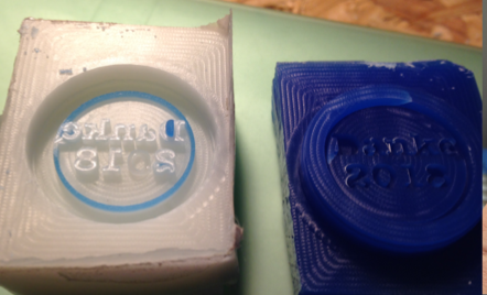
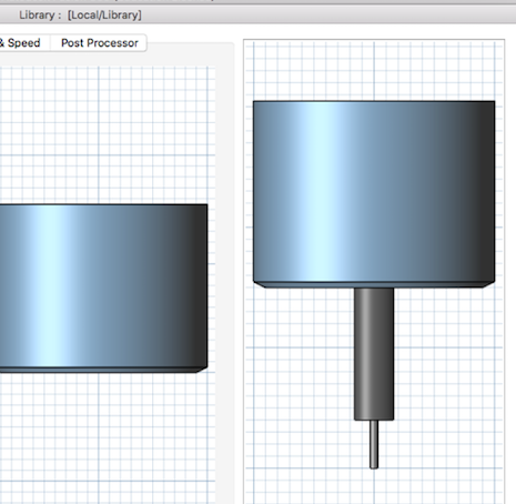
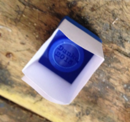
- So I decided to make a mold for a simple coin. To make a negative silicone mold, one have to mill the stock from the top and the model has to be positive.
Design
- After installing, with “File” > “New Design” you can create a new design. I found it quite useful that everytime you save, it creates a new version in a version control software
- Fusion supports sketches as well as primitive solids
- I was alway found of the circular letters on coins. With Inkscape it was possible to align text to a path which was a circle.
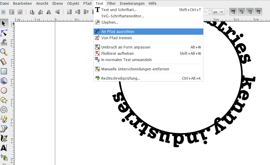
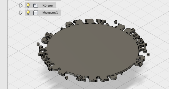
- It was possible to import the svg file and extrude it, but many detail was lost and Fusion crashed several times so I gave it up.
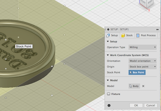
Setup
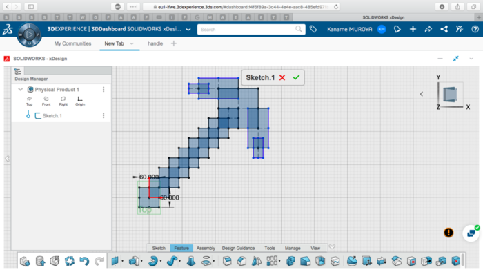
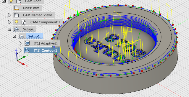
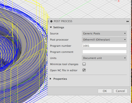
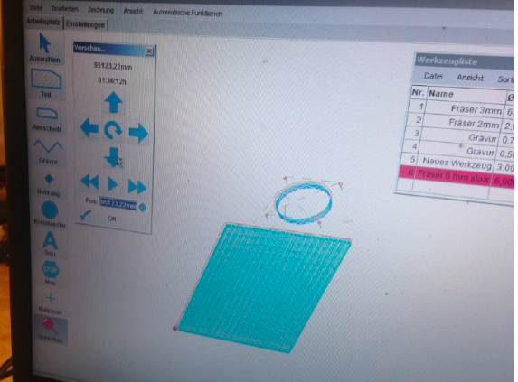
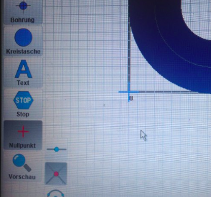
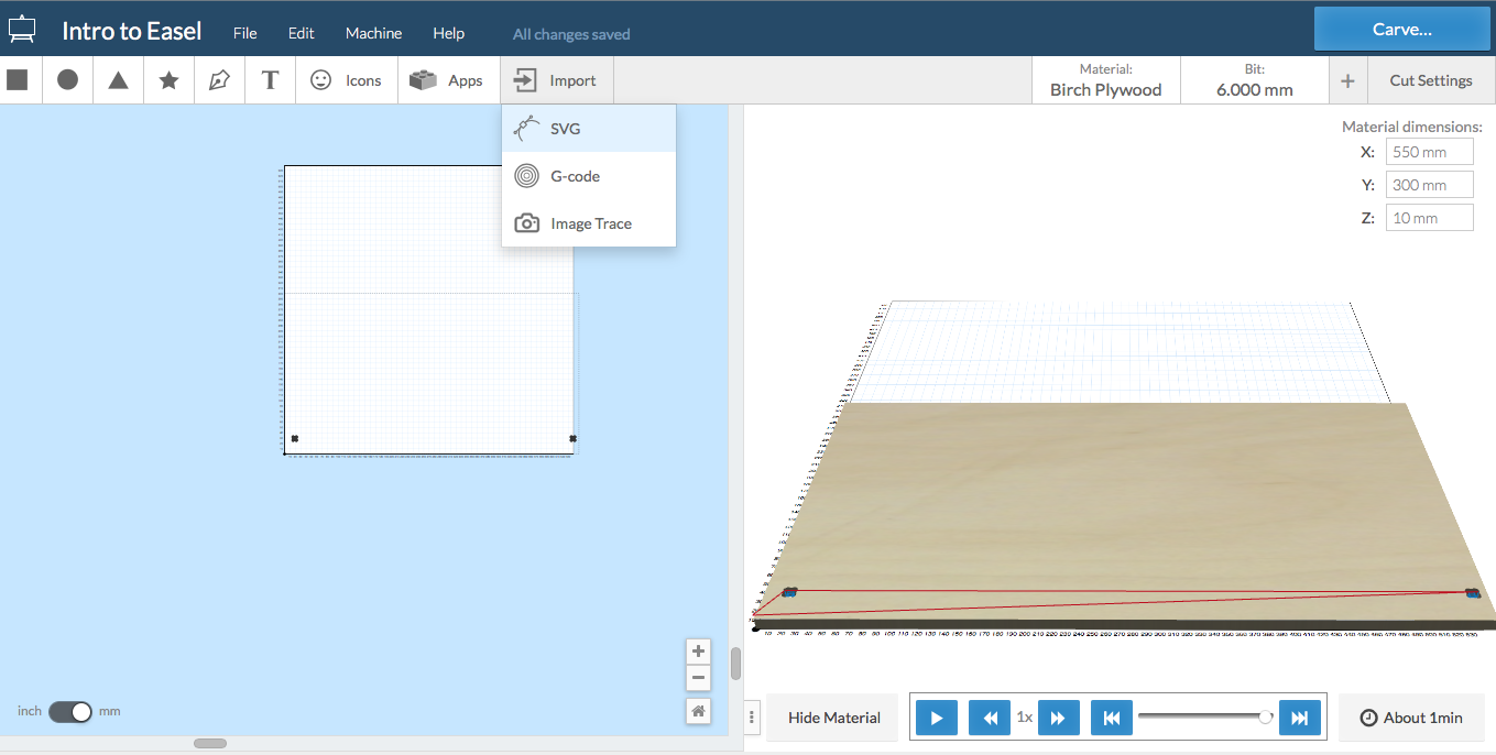
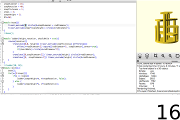
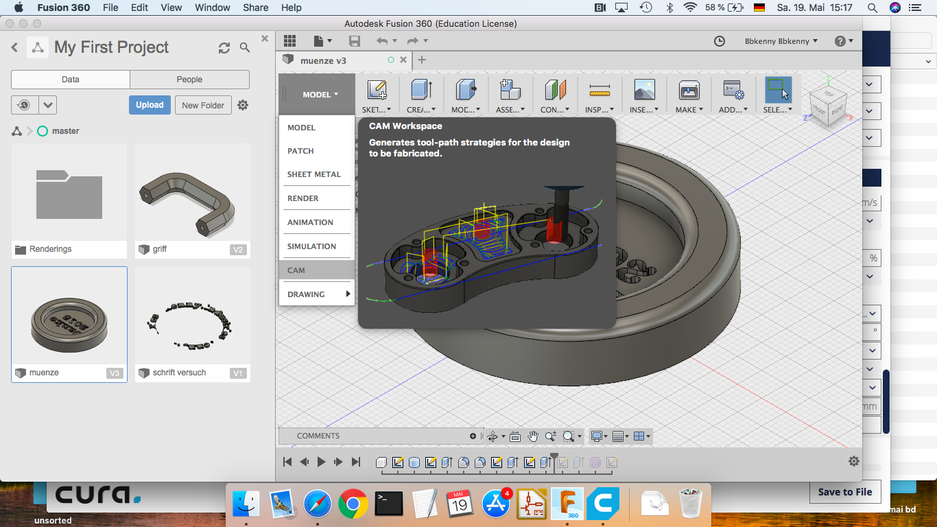
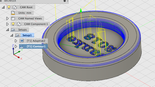
- After swiftly designing the coin by extrude-cutting the center groove and simple text, you open “MODEL” > “CAM” to start preparing the model for cnc machining.
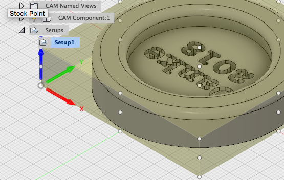
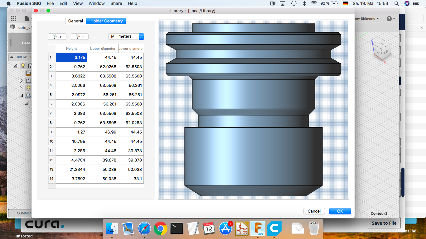
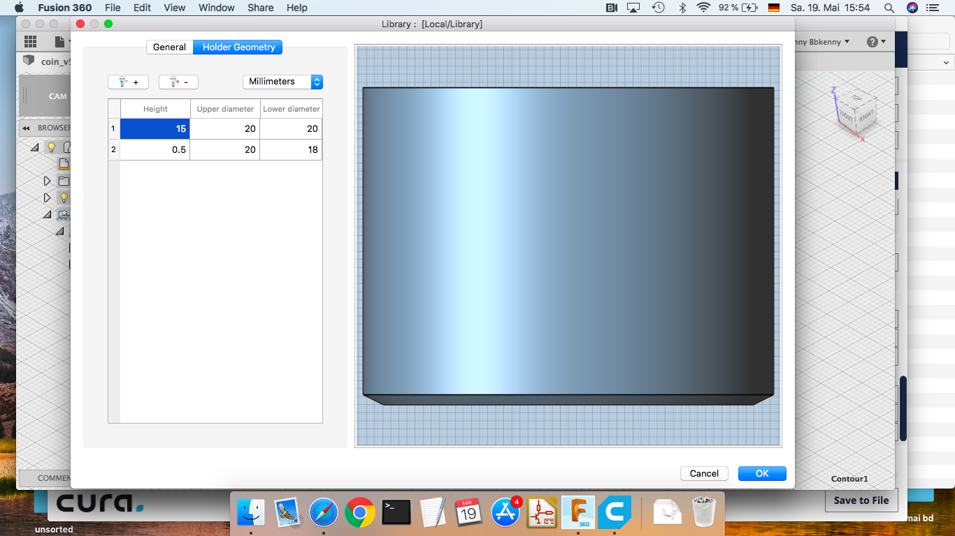
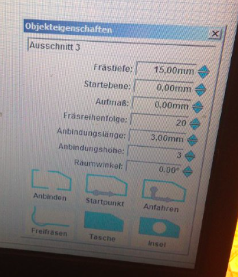
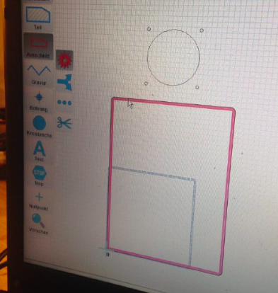
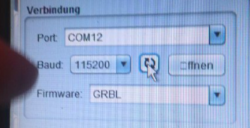
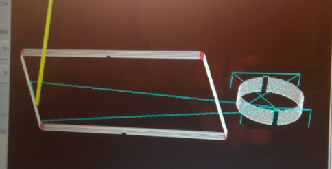
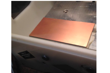
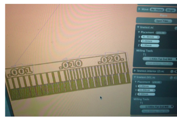
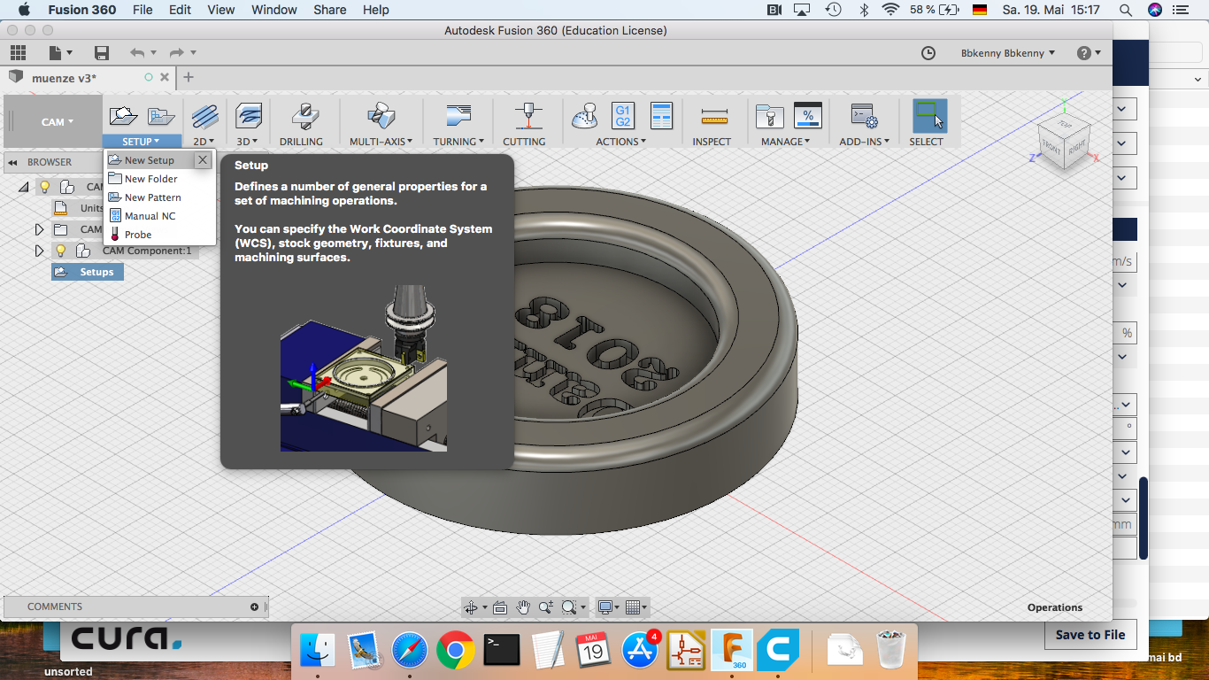
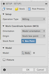
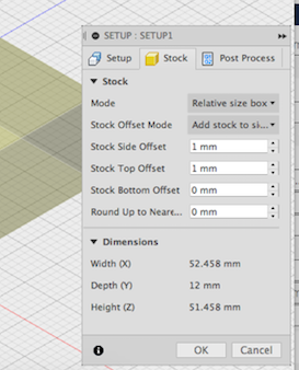
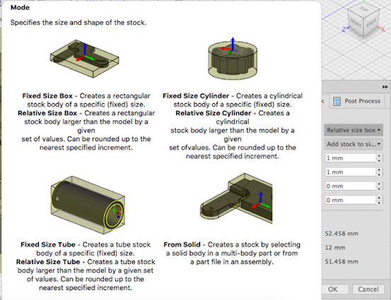
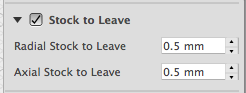
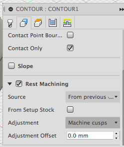
- In the CAM view, first we have to create a new Setup by clicking on “Setup” > “New Setup” on the top toolbar to configure the stock. Here are some configuration I had.
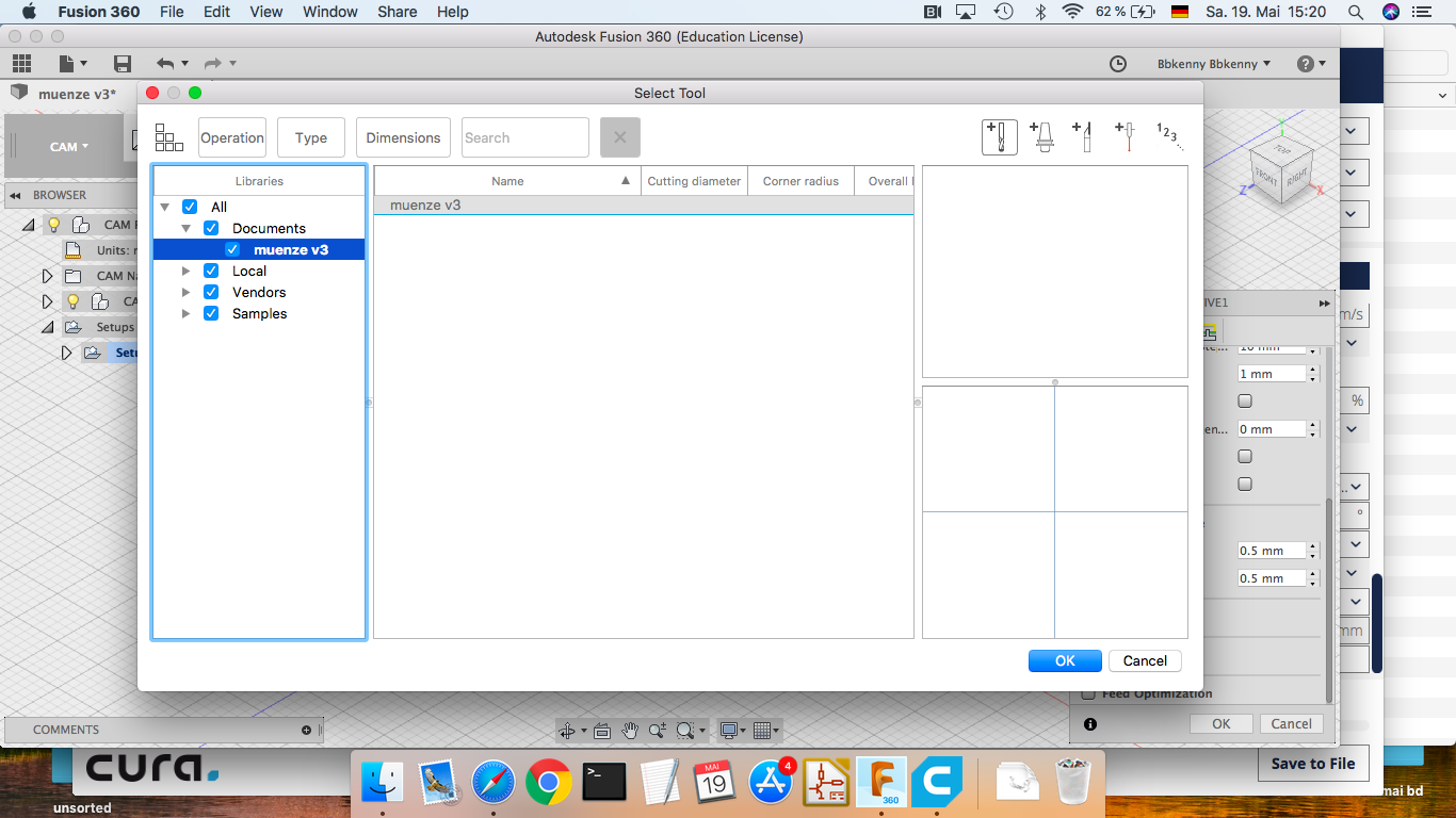
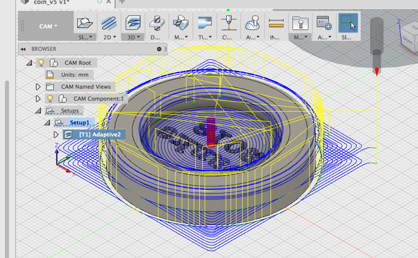
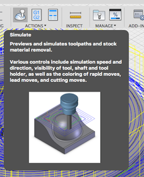
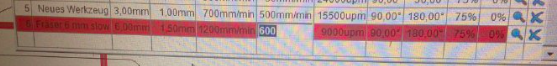
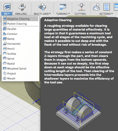
 * For the rough cutting you need to select from the tool bar “3D” > “Adaptive Clearing”
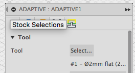
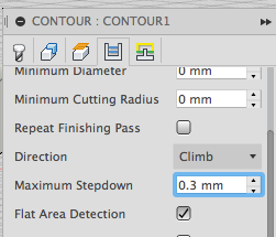
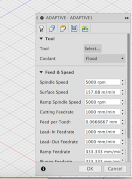
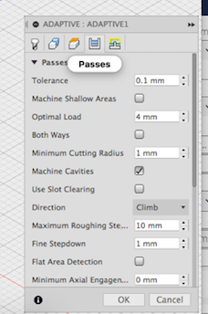
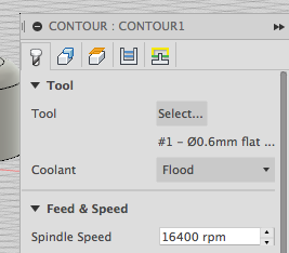
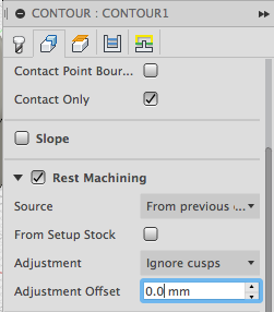
 * Here are some configurations for the actuall milling and the the roughness/passes of the clearing.

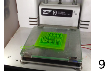
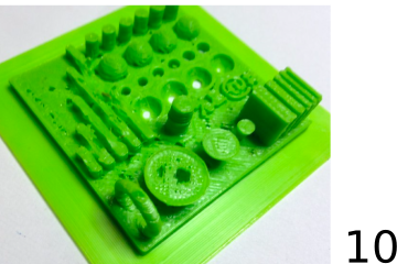
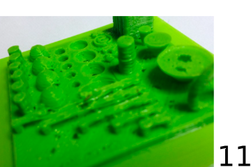
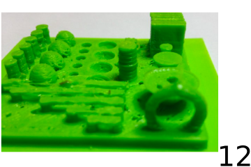
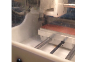
Fabrication
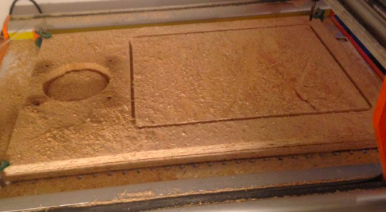
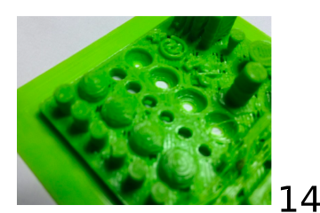
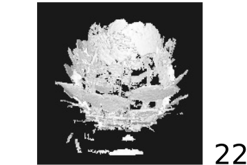
- Rough cutting
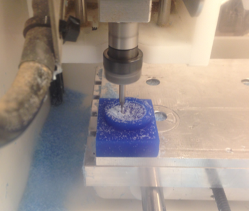
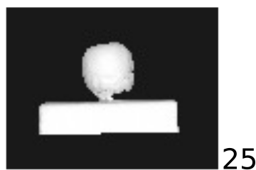
- Fine cutting
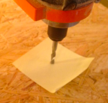
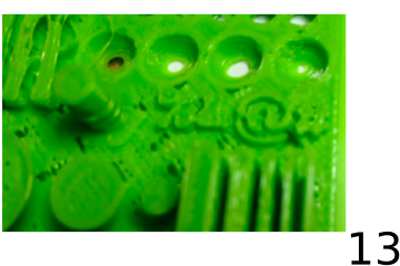
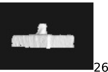
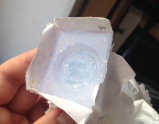
- To clear out all the remaining wax from the cracks, I used compressed air.
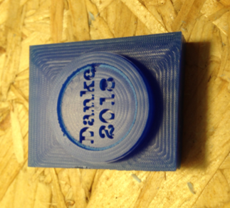
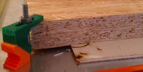
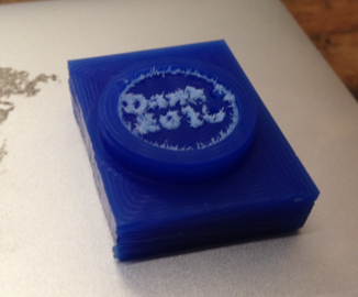
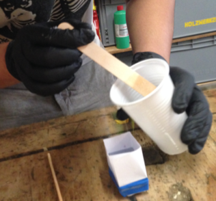
- I could have milled the outside boundary to pour in the silicone, but it would have required bigger chung of wax and more time, so I taped some paper onto the wax with a rubber band.
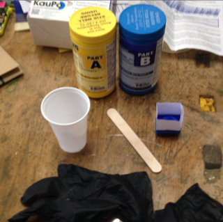
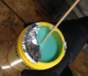
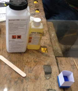
- But the silicone was already hardened because we did not use it for 3 years, so for a quick fix we used epoxy and silicone for seams, which unfortunately was not dry engough and was partly destroyed.
Files