Week 7
Computer-controlled machining
The theme of this week was "Computer-controlled machining", which allowed us to learn how to use CNC machines and understand the many possibilities of CNC machining.
The objective of this assignment were:
The objective of this assignment were:
- Make something big (on a CNC machine).
It seemed to me that the best way to do this assignment was to design and build a piece of furniture.
I had no experience in the construction of any furniture before, except to have seen my father when I was a child.
He liked carpentry, it was his hobby, he made several pieces of furniture at home.
The first piece of furniture he made was a workbench, so I decided to do the same.
Caution

The formaldehyde, used in its production, is released when the MDF is cut. If it comes into contact with this substance,
it may cause irritation in the eyes and lungs. Therefore, it is important to wear a face shield and
protective lenses when cutting the MDF.

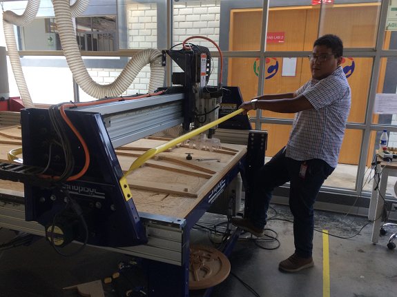
During the operation of the ShopBot it is necessary to use protective lenses against any detaching particles and noise protectors since very high levels are produced.
1. My Design
The material I used was MDF 18mm thick.
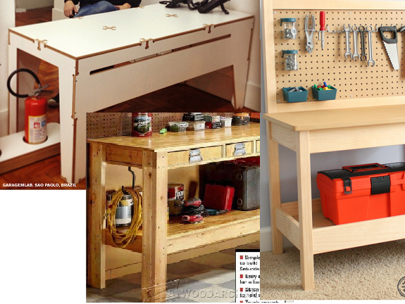
I looked for some work bench reference models, I found some examples of press fit applied to a table, the rest were work benches made with wood.
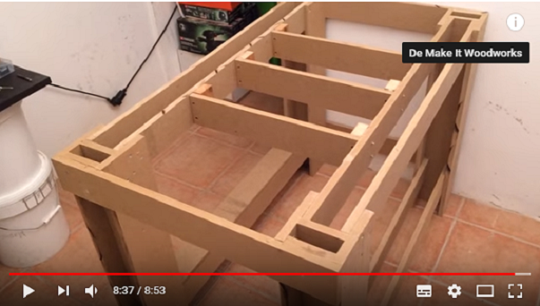
Finally I found a construction video of a workbench with MDF in "Make it Woodworks", but in the video they did not use press-fit but screws and glue. The interesting thing was the way he made the legs of the workbench, he did not join several plates, he used only three to form an "H" profile.
I took that design as a starting point, in that design he used only four legs, to me it seemed that the board would be very weak and could bend, so I increased four more legs to the design, so that there would not be long pieces supporting weight.
I took that design as a starting point, in that design he used only four legs, to me it seemed that the board would be very weak and could bend, so I increased four more legs to the design, so that there would not be long pieces supporting weight.
Ergonomics
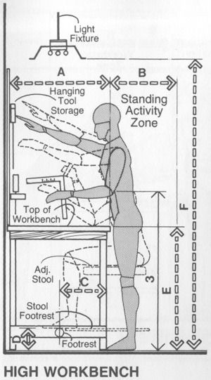
The most important thing about a workbench is its height, which depends on the height of the person who will use it and the work that is done. An inadequate height can cause problems of back pain due to muscle stress. I found a video that helped me define the height.
 How to Chose Your Workbench Height
With that information, I decided that the height of the table should be in the range of 90cm and 92cm. So I hit the legs of the work bench 90 cm high.
The most important thing about a workbench is its height, which depends on the height of the person who will use it and the work that is done. An inadequate height can cause problems of back pain due to muscle stress. I found a video that helped me define the height.
How to Chose Your Workbench Height
With that information, I decided that the height of the table should be in the range of 90cm and 92cm. So I hit the legs of the work bench 90 cm high.
For the location of the workbench I chose a small room of 1.70m x 3.5m that I use as a storage room.
I took the dimensions of the place to include them as parameters in Rhinoceros.
I took the dimensions of the place to include them as parameters in Rhinoceros.
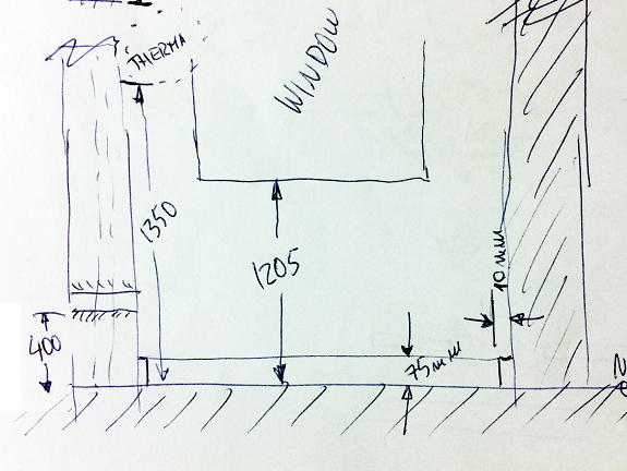 Front view
This is a top view of the same place.
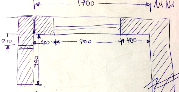 Top view
This was the first design on paper, I changed it because I did not find it very stable for the use I could give it.
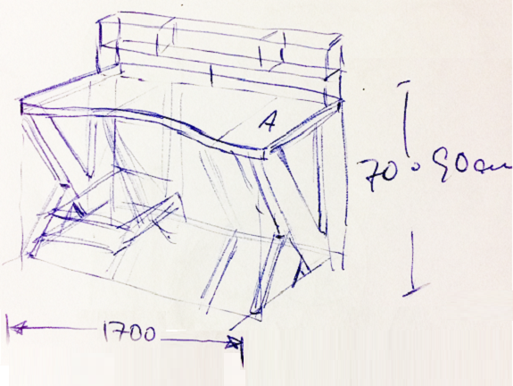 First design
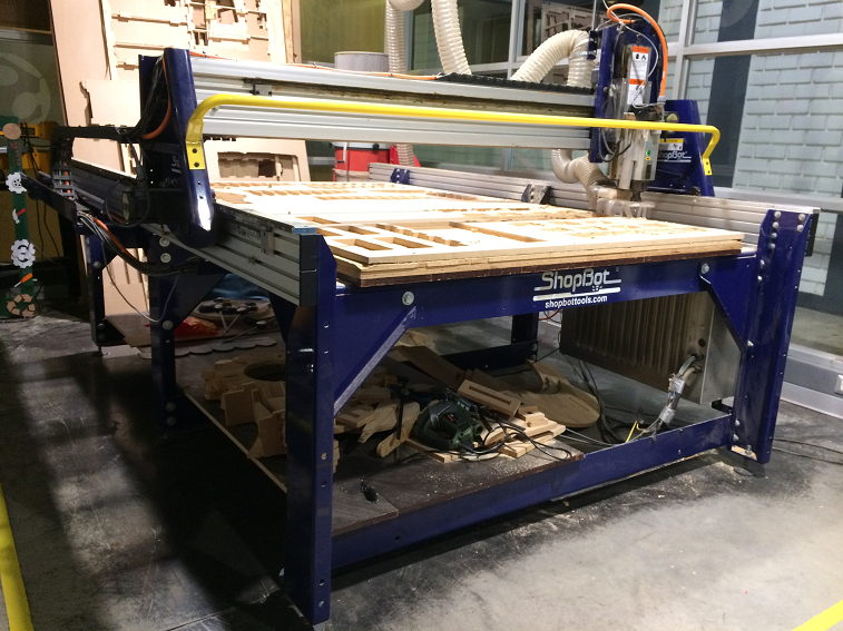
2. Learn to use the CNC machine
Our instructor of the CNC machine Shopbot Víctor Pimentel, showed us the main activities of operation of the machine.
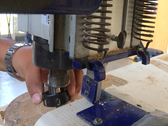
How to change the milling drill.
With the Shopbot turned off we can move the milling carriage forward to make it easier to remove the milling mandrel.
With the Shopbot turned off we can move the milling carriage forward to make it easier to remove the milling mandrel.
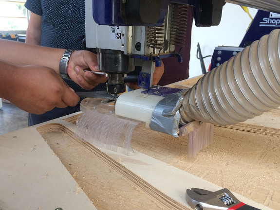
The next step was to loosen a bolt located on the rear of the milling mandrel carriage.
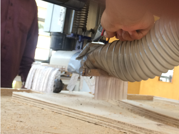
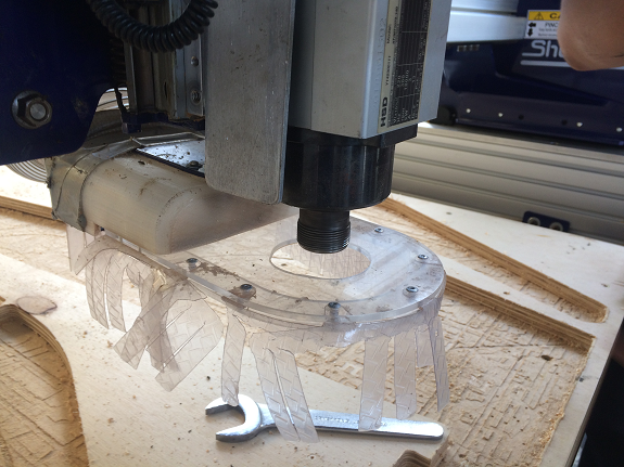
When loosening the support of the system of aspirated of low waste, allowing access to the mandríl of milling.
Here we have a view of the milling carriage without the mandrel.
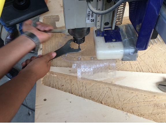
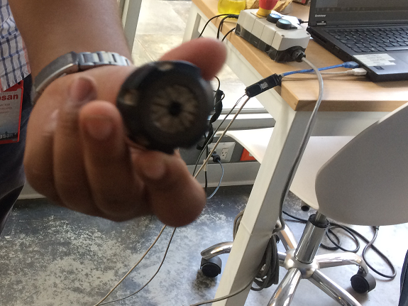
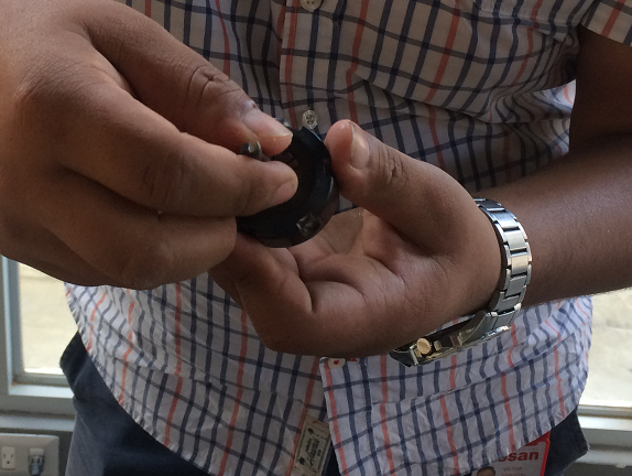
In these images you can see a detail of how the mandríl is. It has metal parts with a spring mechanism, these parts are attached to the milling bit as soon as everything is adjusted to the milling carriage.
After changing the milling bit for the new one, the mandrel was adjusted in its position, using the same tools that were used for the disassembly.
Turning on the machine and emergency shutdown
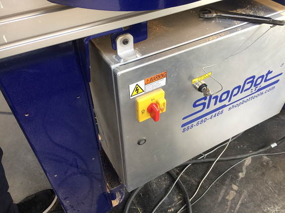
To avoid accidentally turning on the CNC machine, the ignition is divided into two parts: a key and a switch, these are located on the right side of the machine. When they are activated, only turns on the motor system that allows movement in the 3 axes.
For safety, the router's motor is turned on from the program that is on the computer. Be very careful with this, I broke a milling drill for not being careful.
For safety, the router's motor is turned on from the program that is on the computer. Be very careful with this, I broke a milling drill for not being careful.
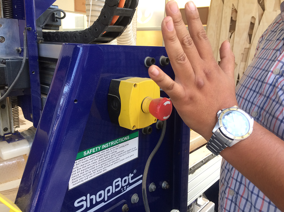
If an emergency occurs during machining there is a red button on the right side of the milling carriage. You just have to press it and everything stops at that moment.
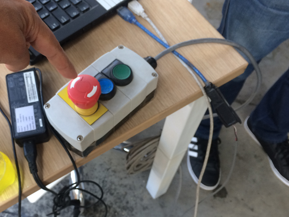
If you are not near the Shopbot there is another emergency stop button located next to the computer.
Calibrate the position of the milling machine
The software of the Shopbot has a functionality that allows to calibrate the exact position of the milling bit. When activated, the milling carriage moves to the position x = 0, y = 0, ie to the left front corner.
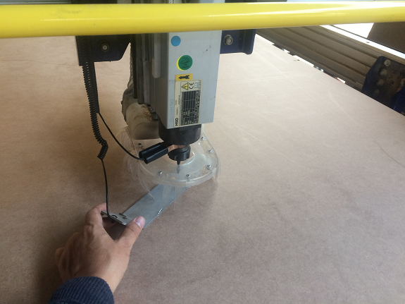
The calibration of the vertical axis Z, is made in combination with a metal plate that is placed under the milling drill, on the material to be milled and a clamp that is clamped from the neck of the milling mandrel.
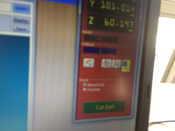
Both, the metal plate and the clamp are connected to an electrical sensor.
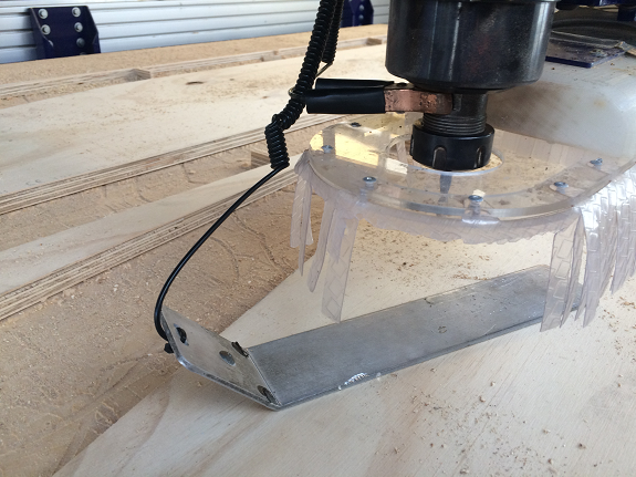
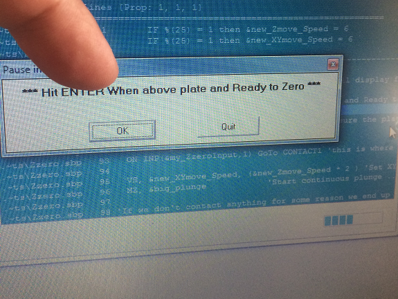
From the program the calibration of the Z axis is activated, at that moment, the milling bit goes down and stops as soon as it touches the metal plate, this process is repeated twice. After this, you are ready to mill.
Other safety regulations
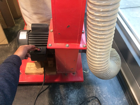
- Before turning on the milling machine, the sawdust vacuum system must be switched on.
- During the milling process, the yellow line on the floor must not be crossed.
- Always wear eye and ear protectors
3. Make press-fit test.
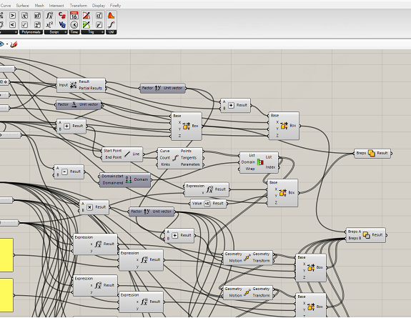
To know the adequate tolerance for the "press-fit" of my work bench, I made a Rhinoceros Grasshopper a parametric model.
Here you see part of the parametric definitions to create the test object.
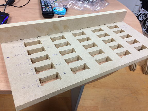
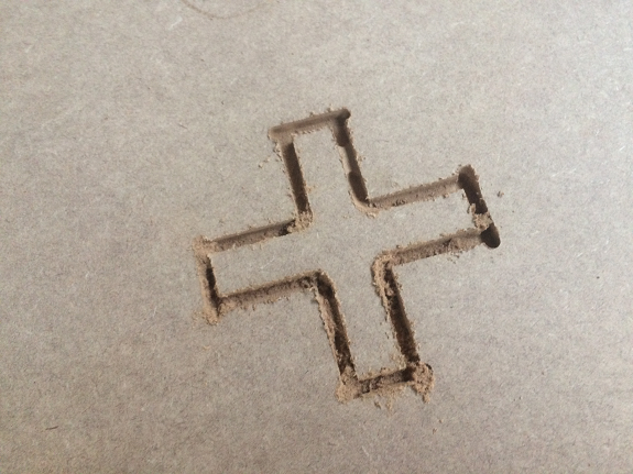
First minutes of the milling process
The milling process took 10 minutes.
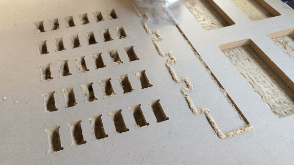
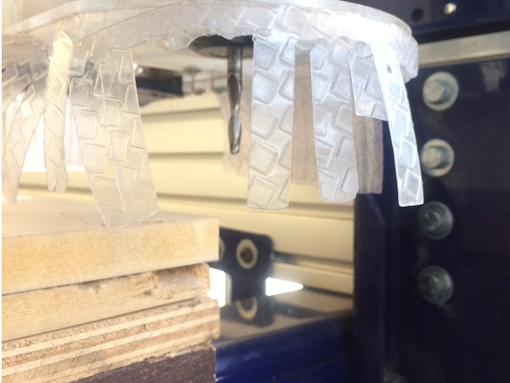
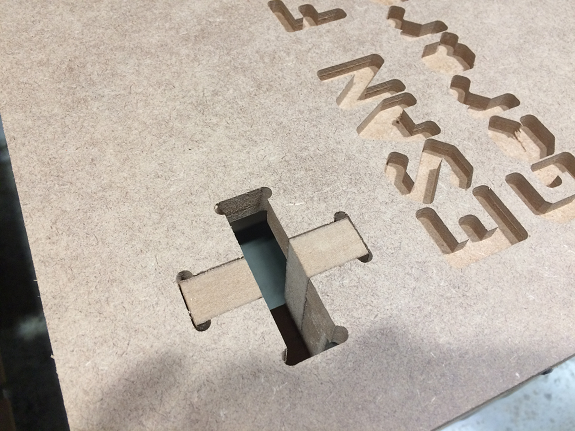
These are the pieces ready for the "press-fit" test with different tolerances.
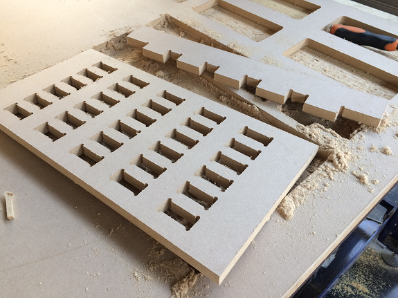
After testing the different adjustment tolerances, I chose 0.6mm, because with that tolerance the joints are made under pressure but the material is not deformed, although it is not easily removed.
Files to download
4. Make a parametric 3D design
The design took me much longer than expected, due to the large number of pieces and press-fits, this delayed me in the rest of assignments.
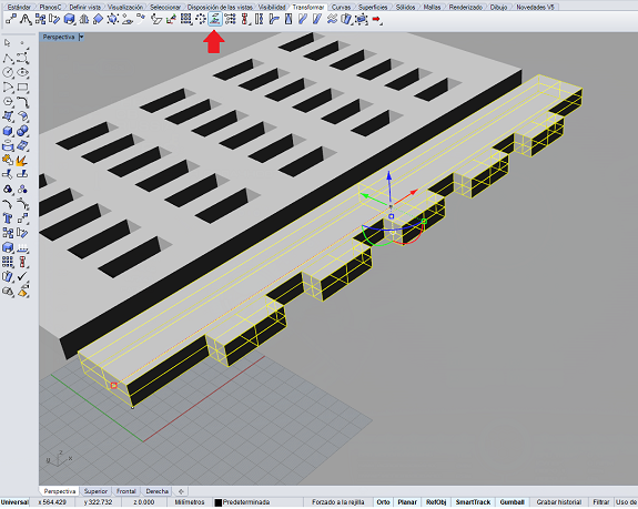
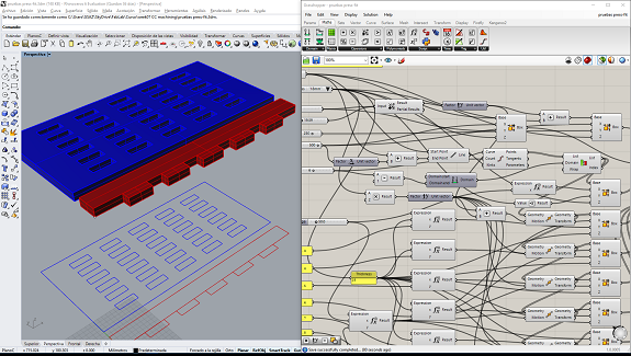
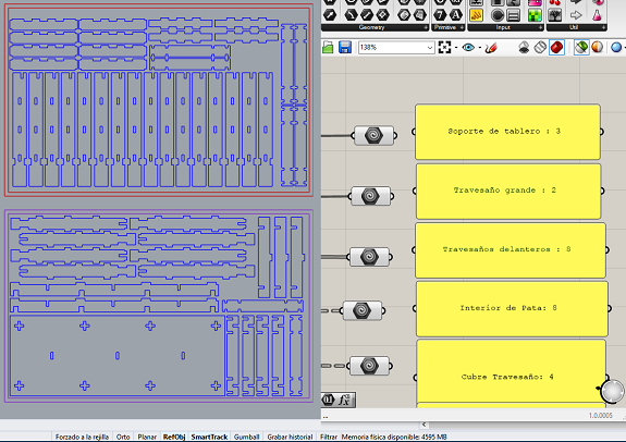
This is a general view of all the objects and how they relate to each other.
This is a general view of all the objects and how they relate to each other.

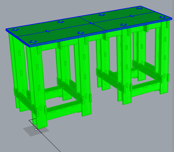
I selected the pieces one by one and used the "Bake" component to turn them into objects in Rhinoceros.
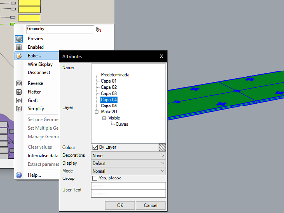
In this image you can see the workbench during the conversion process to 3d objects from Grasshopper to Rhinoceros.
Assembly check
To make sure that nothing is missing and that it is possible to assemble the "Puzzle", I decided to do a 1:10 scale test of the workbench using the laser cutter and a 3mm MDF plate.
To make sure that nothing is missing and that it is possible to assemble the "Puzzle", I decided to do a 1:10 scale test of the workbench using the laser cutter and a 3mm MDF plate.
As all the design is parametrized, I changed the thickness of the material to 30mm, so that when reduced to scale it is 3mm. This is necessary because many pieces have "press-fit" widths or holes depending on the thickness of the material.
I align the converted parts into Rhinoceros objects and convert them from 3d to 2d with the "Make2d" command in the top view, then I use the "Scale" command with the 0.10 factor to reduce everything to one tenth of its size.
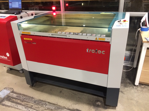
After having all the pieces located in the same plane, it is selected and exported as a DXF file, to be opened in the computer that is connected to the Trorec. The DXF file is read from Coreldraw, there it is given the "last adjustment", all the lines must be with the attribute of "fine line", the lines that are for cutting in red color and the lines for engraving in black color.
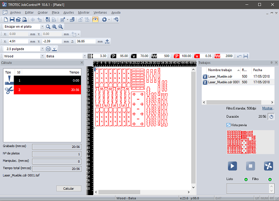
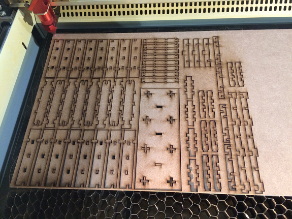
The laser cutting process took 20 minutes
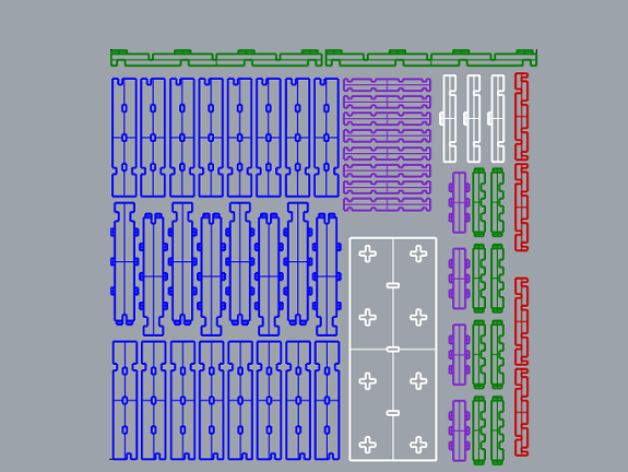
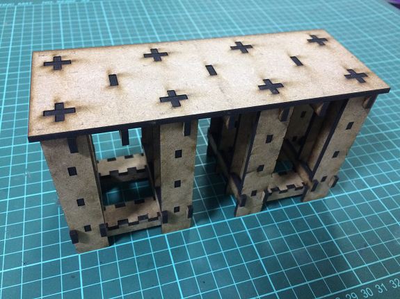
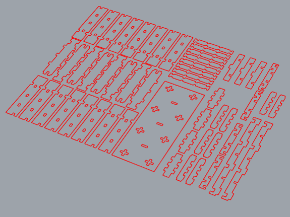
These are the 1:10 scale pieces for the test.
These are the 1:10 scale pieces for the test.
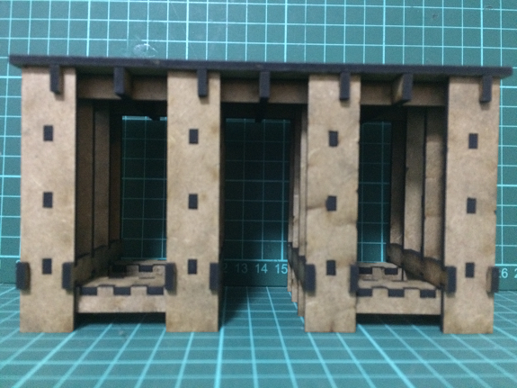
Here we can see some views of the scale model of the work bench, everything fits! It looks very stable and resistant.
Note that the legs look a little thicker than in the design, because their widths are depending on the thickness of the material.
Note that the legs look a little thicker than in the design, because their widths are depending on the thickness of the material.
Ready to do it on a real scale.
Files to download
5. Adjust the design.
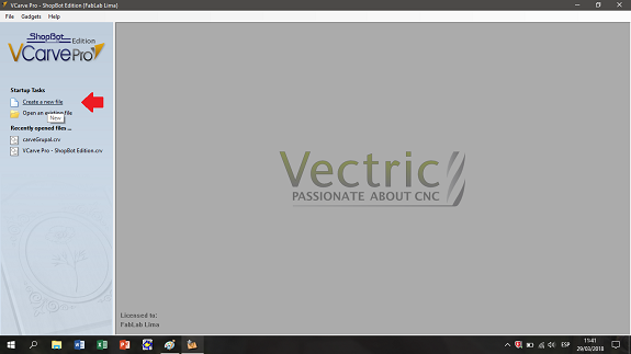
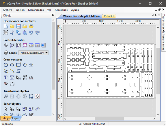
The preparation of the milling work is done in the VCarve software.
With this program the unions of all the vectors that form each object that will be cut or engraved with the milling machine are verified.
To solve the case of cutting straight inner corners with a circular milling bit, VCarve has the Dog-bone or T-bone tools.
With this program the unions of all the vectors that form each object that will be cut or engraved with the milling machine are verified.
To solve the case of cutting straight inner corners with a circular milling bit, VCarve has the Dog-bone or T-bone tools.
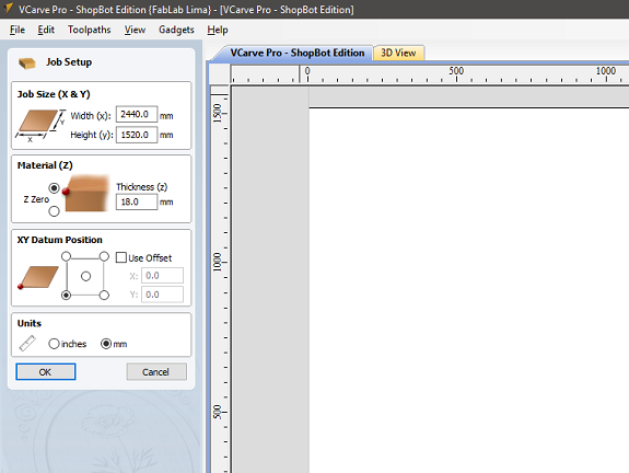
Then, I defined the size and thickness of the MDF board.
Width: 2440 mm
Height: 1520 mm
Thickness: 18 mm
Width: 2440 mm
Height: 1520 mm
Thickness: 18 mm
At Rhinoceros, I re-located all the pieces to save the maximum space, taking into account the dimensions of the MDF board.
According to my calculations I would need 2 MDF boards.
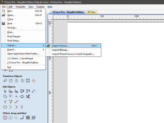
I selected only the pieces and exported them in two DXF files, then I opened them in VCarve.
According to my calculations I would need 2 MDF boards.
I selected only the pieces and exported them in two DXF files, then I opened them in VCarve.
The next step was to import each DXF file into the VCarve to check joints, adjust interior corners and prepare the milling jobs.
Once the DXF file was imported, I selected all the parts and with the tool to transform objects I moved them to the work zone.
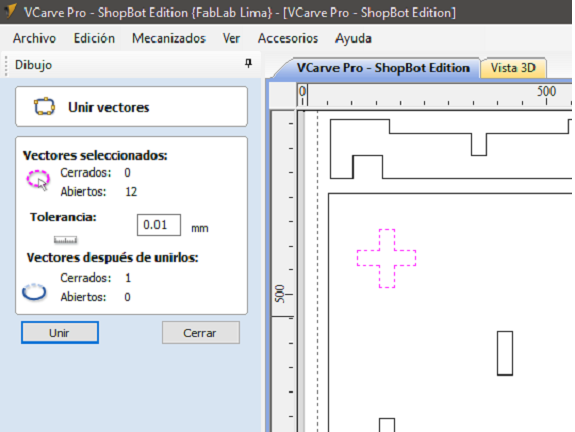
I checked each object, all its lines must be joined, those that were not joined I selected them and with the tool "Join vectors" I turned them into a single object.
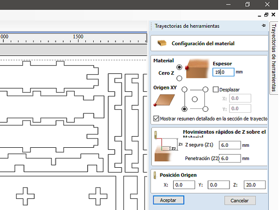
To make sure that the cut of the material is complete, I defined the thickness as 19 mm. This is because the thickness of the MDF boards can vary from one manufacturer to another or due to the effects of humidity.
The next step was to create the milling jobs. For better control, it is advisable to divide them into interiors and exteriors. The red arrow indicates the icon that I used to create the path.
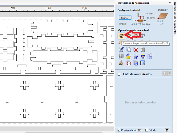
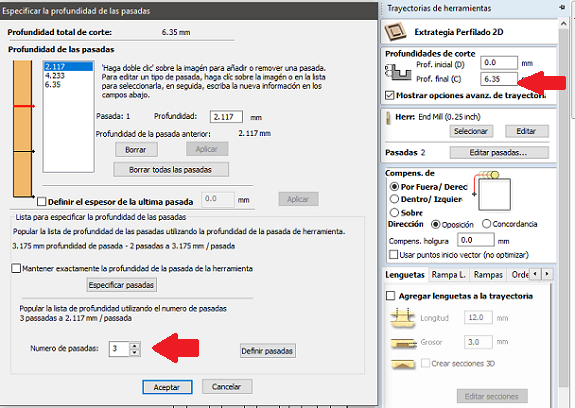
The milling bit I used was 1/4 ", I made sure that this measure was selected.The depth of each pass of the milling bit should not be greater than its width, otherwise, the risk of breakage increases. For that reason and for that thickness of material I assigned 3 passes.
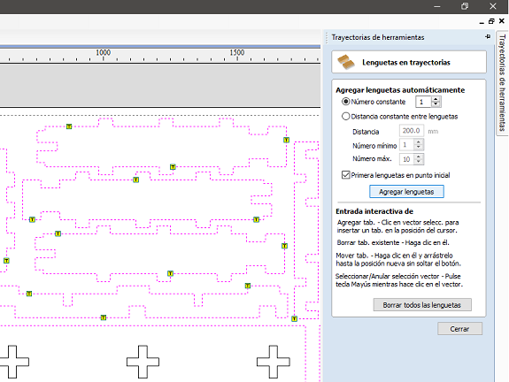
To ensure that no part already cut is moved and causes a bad cut or break of the milling drill or any other accident, you must define fastening points, these can be added automatically or manually. I added them manually, only two per piece and in the same places, so removing them with a rasp is faster.
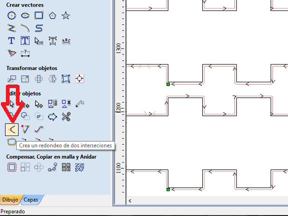
If I had maintained the definition up to this point, the milling bit would have made all the round inner corners and then could not fit any part, to avoid this VCarve has a tool that adds "T-Bone" or "Dog-Bone" to the corners. The arrow points to the access icon.
The radius of cut corresponds to the radius of the milling bit, in my case 3.175 mm. I chose the type "T-Bone"

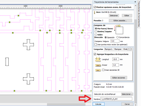
Before saving these definitions, you must select whether the cut will be outside or inside the strokes, in my case I selected from the outside.
The last step of this definition is to save the trace file. For the name, I decided to use a correlative number in front and a letter that indicates the board and a termination that indicates if it is external or internal strokes.
The last step of this definition is to save the trace file. For the name, I decided to use a correlative number in front and a letter that indicates the board and a termination that indicates if it is external or internal strokes.
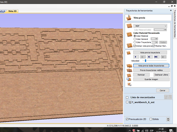
After saving the traces, a milling simulation is displayed.
6. Machining an MDF
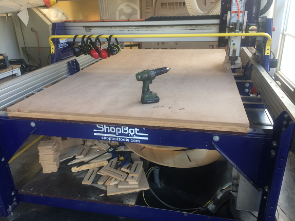
After placing the MDF sheet of 2440mm x 1500mm, I aligned it so that the sides reach the edges of the table.
To prevent it from moving, it must be screwed to the table.
To prevent it from moving, it must be screwed to the table.
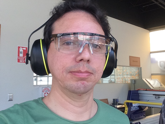
Before starting the work of milling I put the eye and ear protectors.
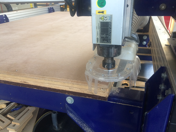
I started the process of calibrating the milling bit.
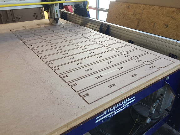
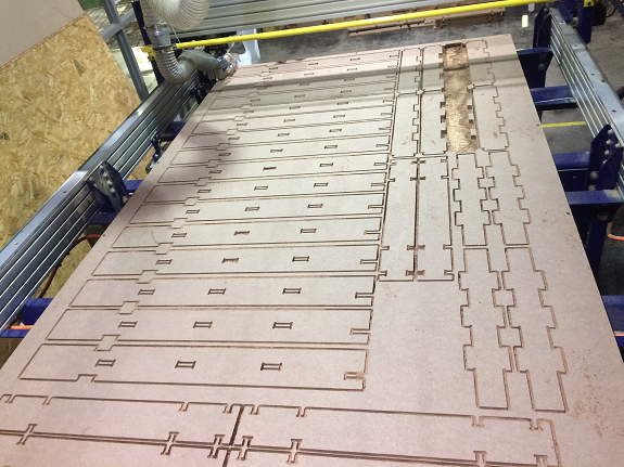
The first work of milling began with the internal strokes of the board.
Problem during the milling
During the milling of the second board a couple of pieces moved from their places. Fortunately, it was not serious, the drill was not broken, and nothing went flying.
This was to locate the pieces very close together. The separation between long pieces was a very thin line and with the thrust of the work of milling moved a few millimeters.
The two pieces were left with a few extra millimeters, so I passed them a rasp and a sandpaper until I reached the correct size.
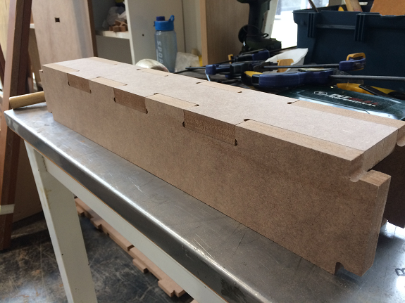
7. Check the parts and put everything together.
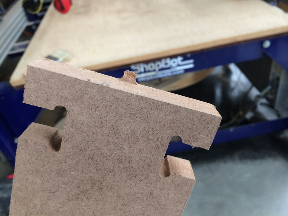
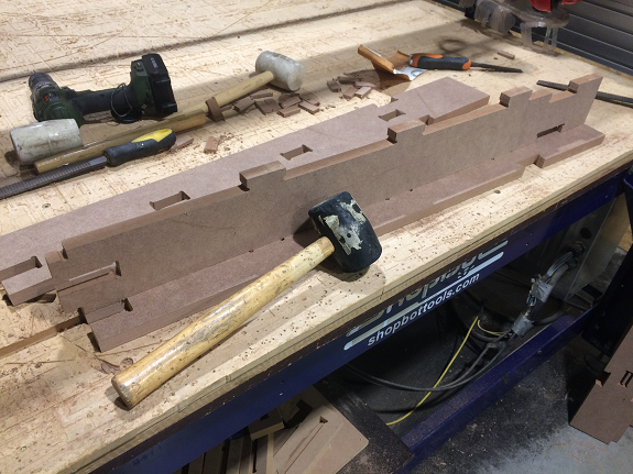
The cuts of the pieces were exact and clean. He only had to remove the clamping tongues with a rasp or chisel with a mallet.
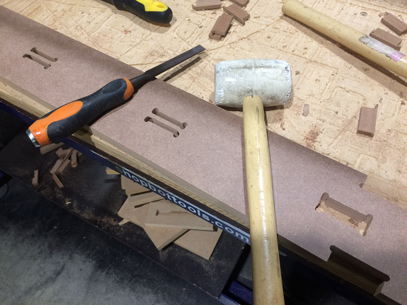
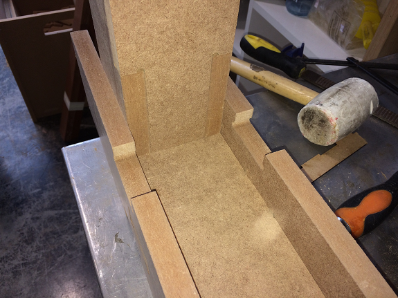
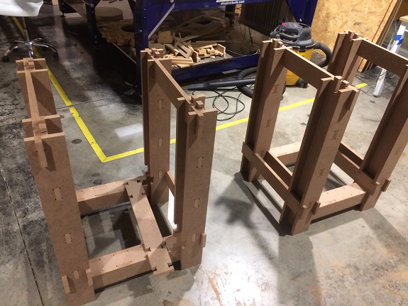
After removing the clamping lugs, I began to assemble the legs of the workbench. The assembly was with adjustment, so it was necessary to use a mallet.
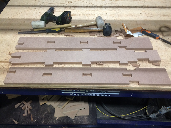
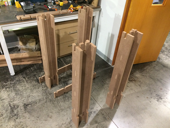
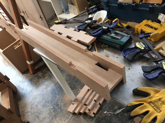
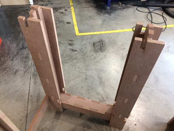
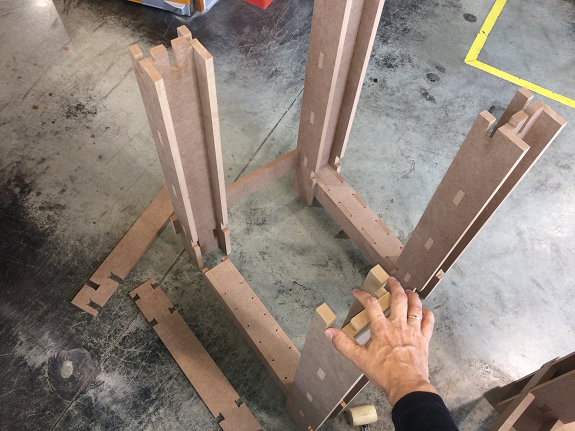
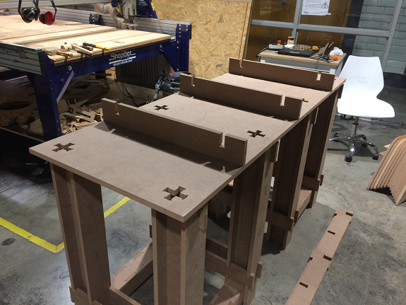
I align my legs to give me an idea of the space it would occupy.
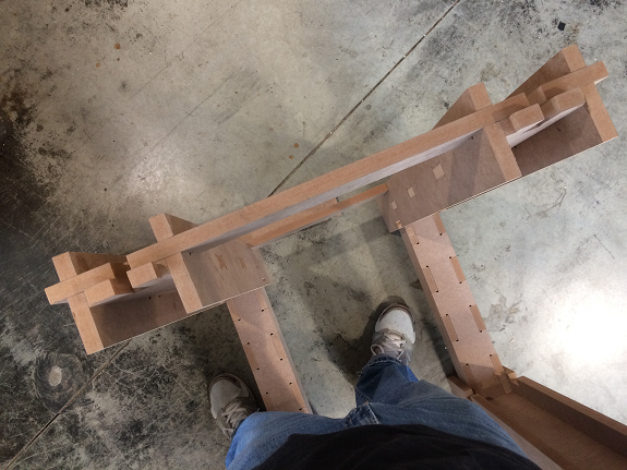
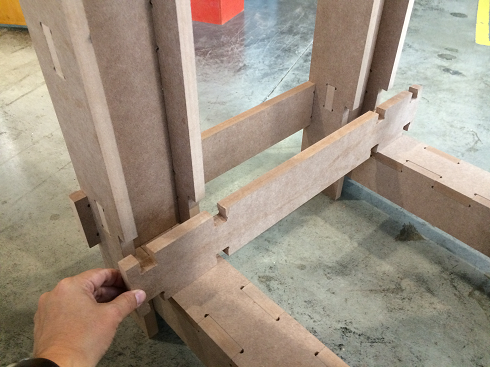
So I built the lower crossbars, everything to press-fit.
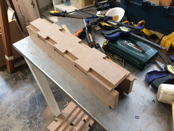
In this way, assemble the lower crossbars to the legs.
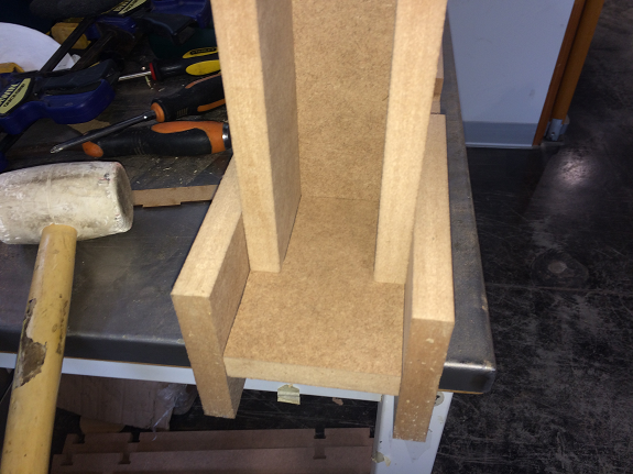
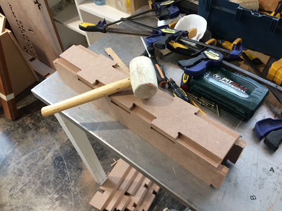
After aligning the legs I tried the assembly of one of the short crossbars. The assembly was effortless, only with the hands, in this place that is not a problem, since the weight of the board will keep the rest together and the function of this piece is to keep the legs in place.
The union of the parts is exact, fit without the need to use a mallet.
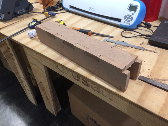
Another view of the union of the pieces that form the legs.
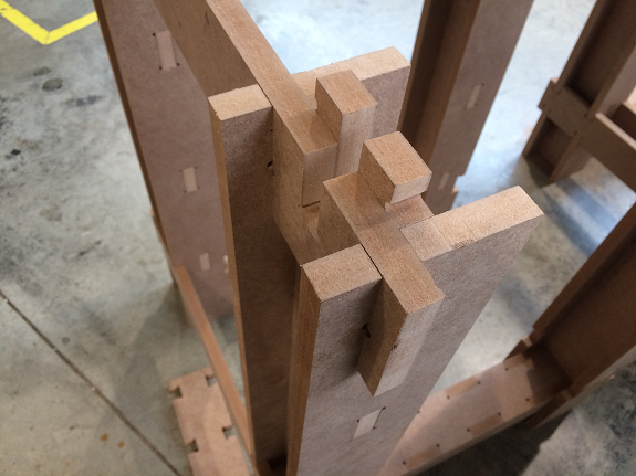
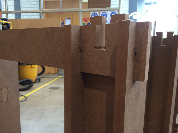
These pieces did need a rasp pass, because I did not consider that the lower crossbar (the three-piece) would push the H-shaped legs outwardly, separating the joints. If you had used a mallet to assemble it, it is very likely that something would have broken.
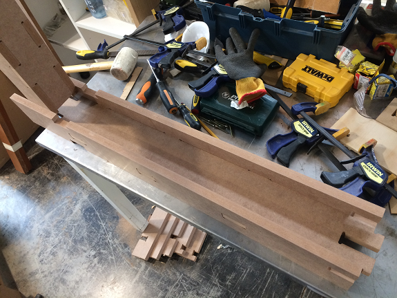
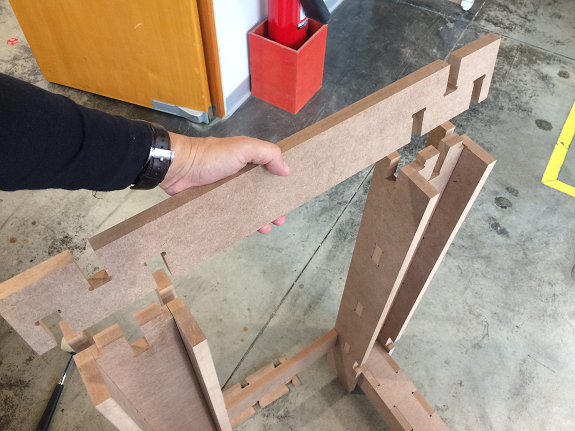
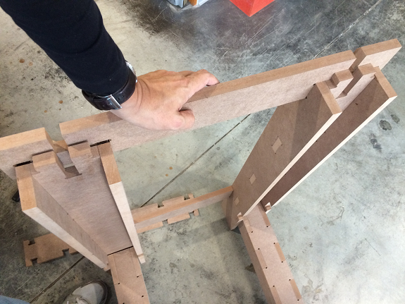
Now all the pieces fit, the next step is to try the assembly of the long upper crossbars.
To verify the materials, I tested the parts separately.
To verify the materials, I tested the parts separately.
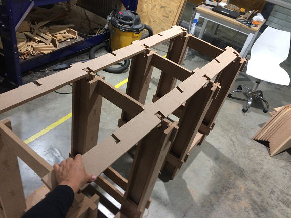
Test of board and legs, without long crossbar .... Ok.
Testing the short crossbars, his press-fit was accurate.
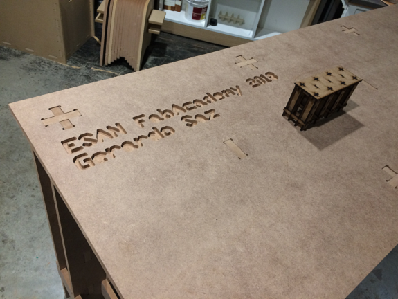
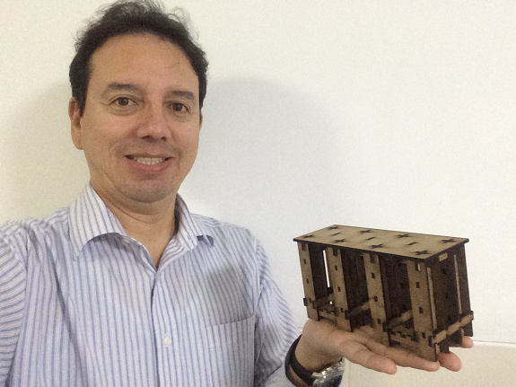
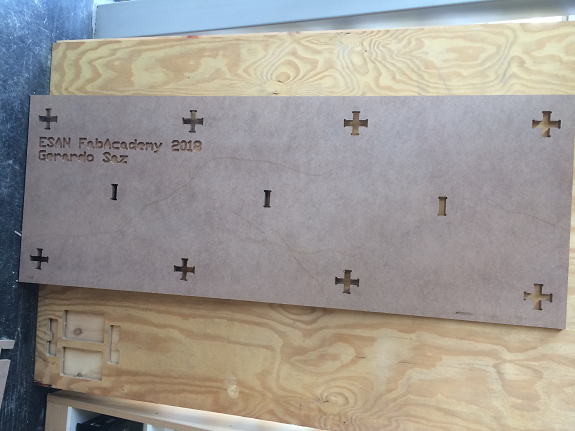
The work bench is ready!, I took a picture with the holding in hand the scale model made previously.
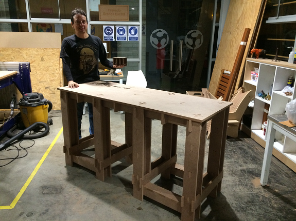
In this photo you can see the detail of the engraving and the model made to scale 1:10.
Files to download
Files to download