Week 8
Embedded programming
The theme of this week was "Embedded programming", that gave us the opportunity to learn other programming languages.
The objective of this assignment were:
The objective of this assignment were:
- Read a microcontroller data sheet.
- Program your board to do something, with as many different programming languages and programming environments as possible.
My Workplan
My workplan was as follows:
What is an embedded program?
It is a program that is inside a controller and that has a specific task. This program has been designed taking into consideration the limitations and capabilities of the controller and the components to which it is connected.
Microcontroller DataSheet: ATTiny44a
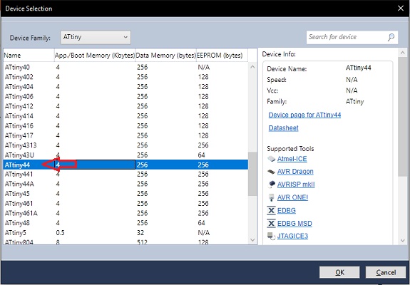
The datasheet I read was that of the ATtiny44, which is the microcontroller that I have used in the "Hello-world" PCB.
 ATtiny44datasheet.pdf
ATtiny44datasheet.pdf

On the first page the summary of the characteristics of the microcontroller is shown.
Among them, 8-bit microcontroller with high performance and low power, capacity for 120 instructions, high persistence memory, can hold up to 100 years at 25°C or 20 years at 85°C, operating voltage between 1.8V and 5.5V, industrial operating temperature between -40°C and 85°C, universal serial interface, in-system programming via spi port.
Among them, 8-bit microcontroller with high performance and low power, capacity for 120 instructions, high persistence memory, can hold up to 100 years at 25°C or 20 years at 85°C, operating voltage between 1.8V and 5.5V, industrial operating temperature between -40°C and 85°C, universal serial interface, in-system programming via spi port.
The structure of the datasheet is as follows:
- Pin configurations
- Overview
- Additional information
- Registration summary
- Summary of instruction set
- Order information
- Packaging information
- Errata
- Datasheet Revision History
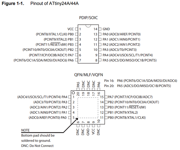
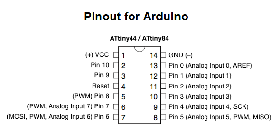
In the "Pin Configuration" section we see a couple of schematic diagrams of the formats in which 14 and 20 pins are available (although only 14 pins are used in the last one).
Followed by an explanation about the functions of each pin.
Three pins are intended for: supply voltage (VCC), earth (GND) and reset, the rest are divided into two groups: ports A and B.
Port A is 8 bits of bidirectional input/output analog, port B has 4 bits of bidirectional input/output, both ports have internal pull-up resistors.
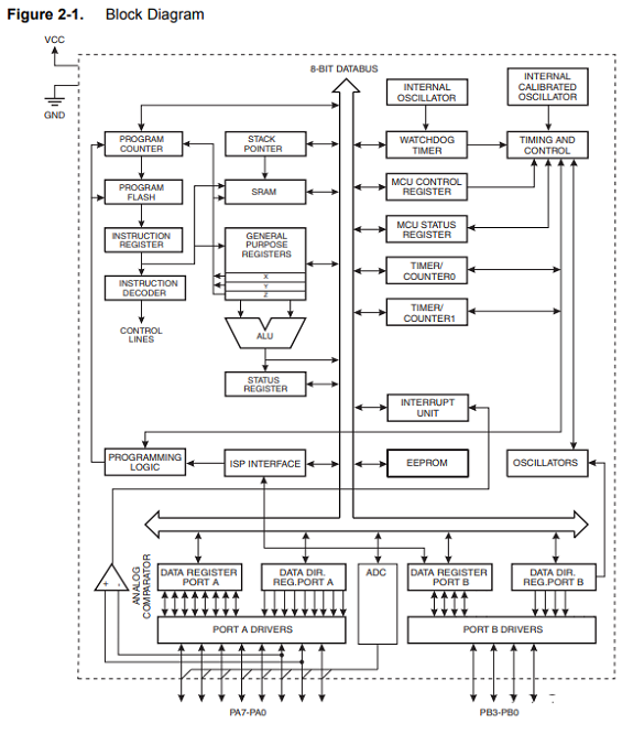
In the "Overview" section, a block diagram of the microcontroller is shown, followed by a summary explanation of the functions of each component.
In the "Instruction Set Summary" section there is a table with the list of instructions and a short description.
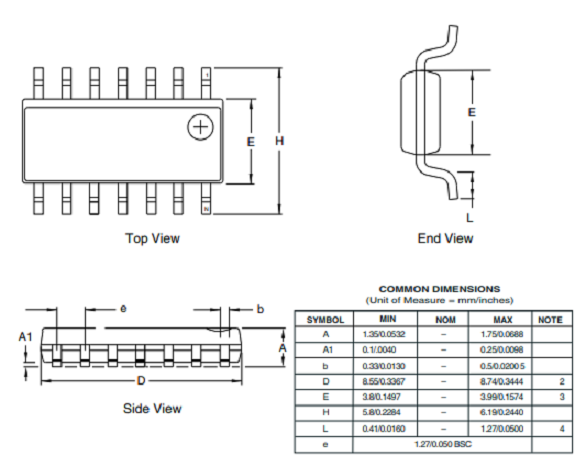
In the "Packaging Information" section, a plan of the controller is shown with a table containing the exact dimensions
In the "Packaging Information" section, a plan of the controller is shown with a table containing the exact dimensions
Conclusion:
I have a microcontroller with 12 pins (8 pins for port A + 4 pins for port B). The pins of port A can be used to read the signal of up to 8 analog sensors, or if I use both ports I could read up to 12 digital signals, or I could use them to manage 4 servo motors.
I have a microcontroller with 12 pins (8 pins for port A + 4 pins for port B). The pins of port A can be used to read the signal of up to 8 analog sensors, or if I use both ports I could read up to 12 digital signals, or I could use them to manage 4 servo motors.
Programming my board
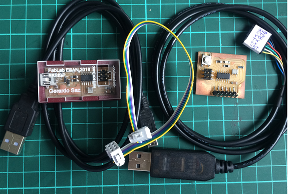
Materials and equipment needed
- My pcb of the assignment "electronic design"
- My FabISP of the "Electronics production" assignment
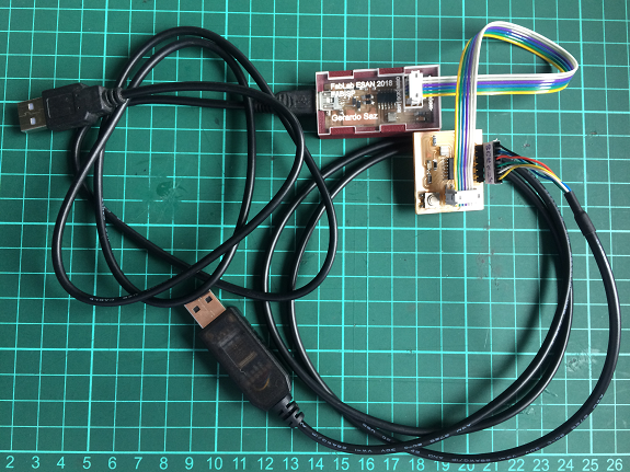
- A 6-wire ribbon cable c
- A USB cable - mini USB
- An FTDI cable
- A computer with USB ports
The assignment asks "Use as many languages as possible".
These are the programming languages that I used.
These are the programming languages that I used.
- C# from Arduino IDE
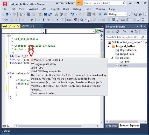
- C from AtmelStudio IDE
1. C# from Arduino IDE
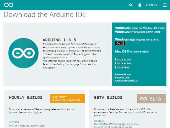
The first thing I did was make sure I had the latest version, so I went to the Arduino website, this is the link
https://www.arduino.cc/en/Main/Software#
The first thing I did was make sure I had the latest version, so I went to the Arduino website, this is the link
https://www.arduino.cc/en/Main/Software#
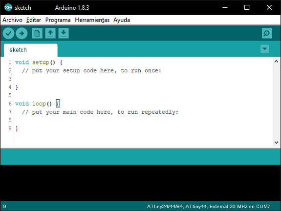
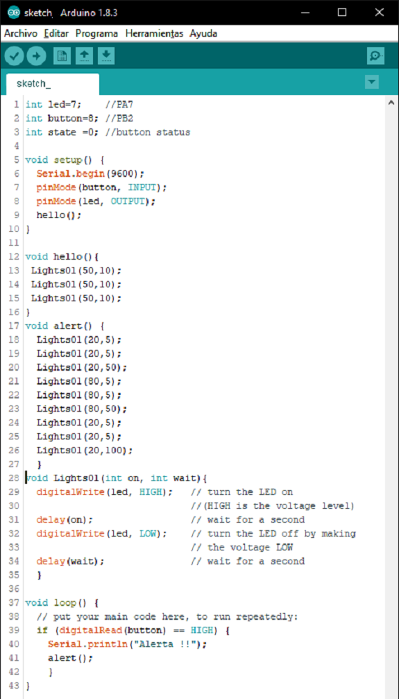
Once installed, run the program. The following image shows how the arduino IDE looks.
At the top is the menu and command buttons, in the central part, the program's editing area, and at the bottom, the compiler's message area.
At the top is the menu and command buttons, in the central part, the program's editing area, and at the bottom, the compiler's message area.
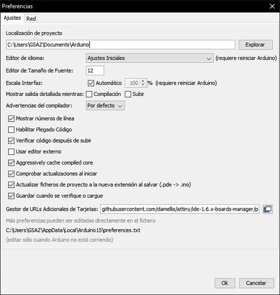
The ATTiny44 driver library is not installed in the Arduino IDE, it must be installed first, so I went to the menu "File / preferences" and where it says "Manager of additional URLs of cards" copy the following:
https://raw.githubusercontent.com/damellis/attiny/ide-1.6.x-boards-manager/package_damellis_attiny_index.json
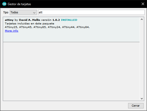
Then I clicked on the menu "Tools / Board / Card Manager" and in the pop-up window I searched for "ATTiny" and installed it.
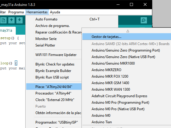
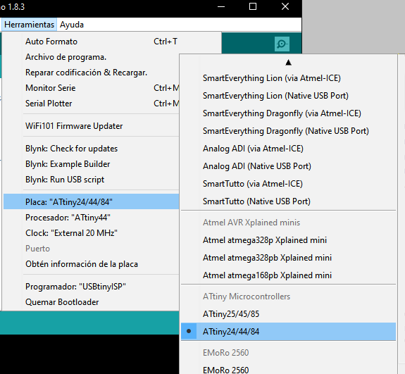
When I returned to the "Tools / Plate" menu in the list of cards I selected "ATtiny24/44/84". Then in the "Tools / Processor" menu I chose "ATtiny44"
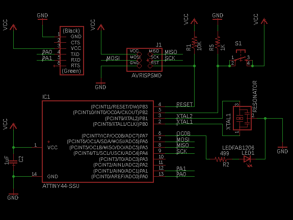
In the schematic diagram the LED is connected to the 6th pin of the ATtiny44, and the button to the 5th pin, these numbers do not correspond to the Arduino numbering.
This table has the equivalence between the ATtiny44 and Arduino controller pins.
So in the case of Led, the 6th pin corresponds to analog input 7 (PA7).
And in the case of the button, the 5th pin corresponds to pin 8 (PB2).
So in the case of Led, the 6th pin corresponds to analog input 7 (PA7).
And in the case of the button, the 5th pin corresponds to pin 8 (PB2).
To test my PCB I made a program that starts blinking the led three times and then if the button is pressed, the led will make three short blinks, three long and again three short blinks.
I connected my FabISP to the computer with the USB cable, the FabISP I connected to my PCB with the ribbon cable taking into account that both GND must be connected with the yellow wire, and my PCB to the computer with the FTDI cable.
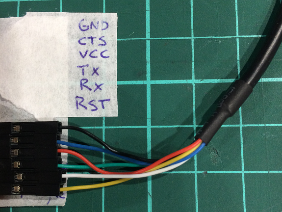
The connection of the FTDI cable is as indicated in the image.
This is the video of the test run of my PCB. Works perfectly with a 3 volt source.

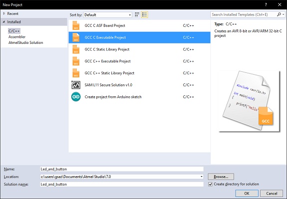
2. C from AtmelStudio IDE
I downloaded the latest version of the IDE, directly from its page:
http://www.microchip.com/mplab/avr-support/atmel-studio-7
I downloaded the latest version of the IDE, directly from its page:
http://www.microchip.com/mplab/avr-support/atmel-studio-7