Week 11
Output Devices
The theme of this week was "Output Devices".
The objective of this assignment were:
The objective of this assignment were:
- Add an output device to a microcontroller board you've designed, and program it to do something
I decided to dedicate this assignment to engines, for my final project I need an engine that takes care of the suction propeller and other motors for the movement.
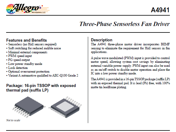
I chose the brushless motor for the propeller of the vacuum cleaner because it is a motor with low noise emission and very fast 7200 rpm approx. the A4941 microcontroller manufactured by Allegro is responsible for speed control.
This is the Datasheet of the A4941 processor
This is the Datasheet of the A4941 processor
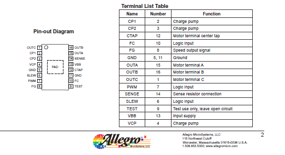
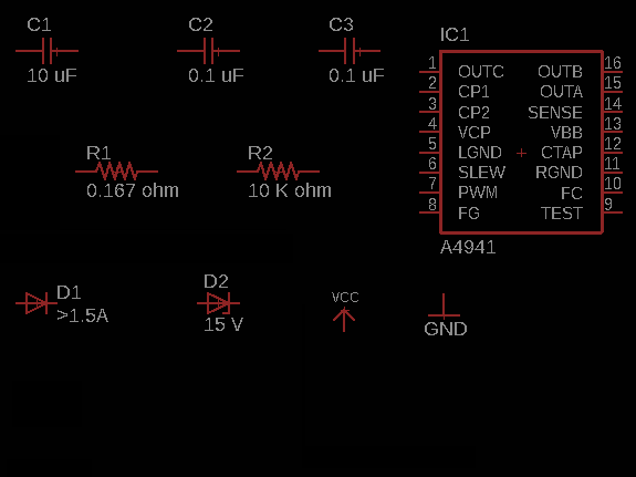
This is the pinout of the A4941 processor, it will guide me to make the schematic diagram
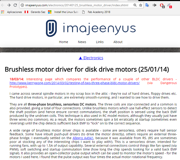
I found a page on which describes the operation of the engine with this processor
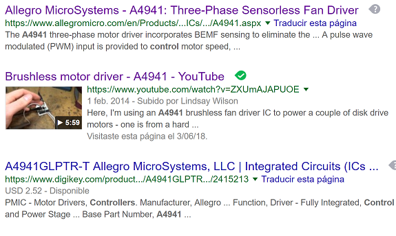
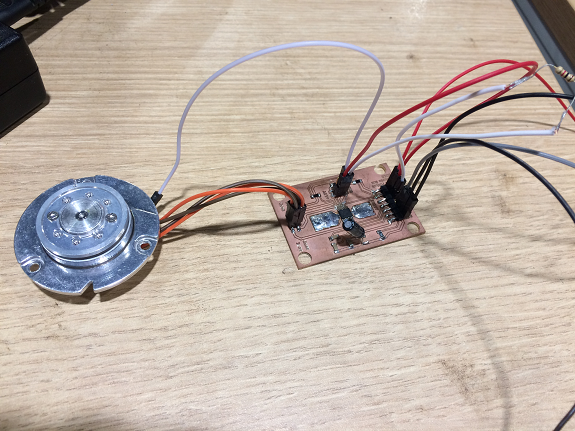
I checked the page and followed some guidelines, using a fan controller to move a hard drive motor.
Brushless motor driver for disk drive motors
Brushless motor driver for disk drive motors
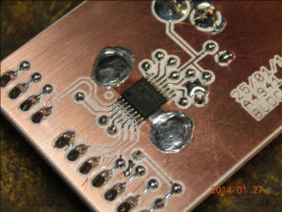 Example taken as a basis for my PCB
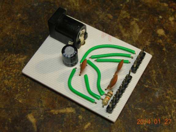 Example taken as a basis for my PCB
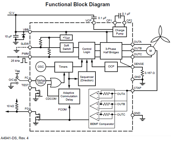
In this diagram the Datasheet explains that:
- SLEW: GND = soft switching, Open = disable
- PWM: Open = full Speed
- FG: Pulse output - divide by 4 to get shaft speed
- SENSE: Connected to 0V via resistor
- FC: has three states: V + 50ms, GND 100ms, Open 200ms
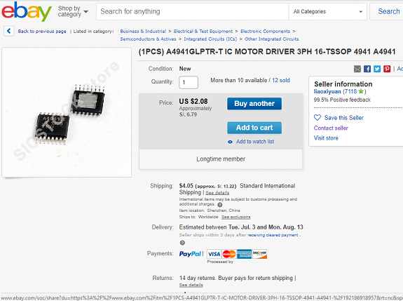
The A4941 processor was not in stock, so I looked for it in electronics stores but I did not find it either. So I bought it from Ebay to a Chinese manufacturer at $ 2.08 each, I bought 8 to have reserve if they burn during use.
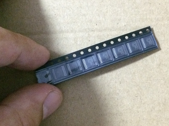
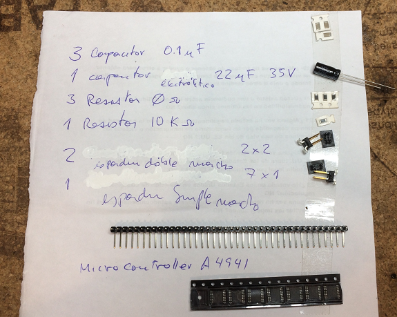
After six days I received a small package with the A4941 drivers, I did not imagine that they were so small.
From the schematic diagram I extracted the list of materials.
- 1 controller A4941
- 1 capacitor 10uF
- 3 0.1uF capacitor
- 1 resistance 0.167 ohm
- 1 resistance 10 K ohm
- 1 zener diode 15v
- 1 diode> 1.5A
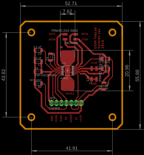
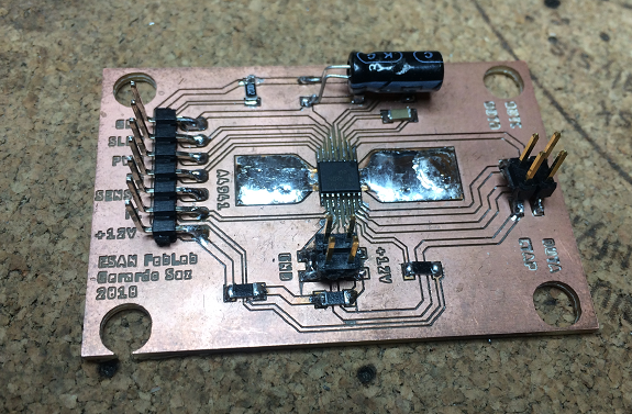
This is the schematic diagram that I made with all the information that I got, to avoid making clues lor the other side I added some resistors of 0 ohm that helped me to make bridges.
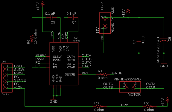
The controller A4941 has a heat sink on the bottom that is connected to Gnd, to help dissipate this heat I made the tracks as thick as possible, and on both sides of the controller I drew a couple of areas to help dissipate that heat , I will not know if it was enough or exessive until I tested its operation.
Files for download
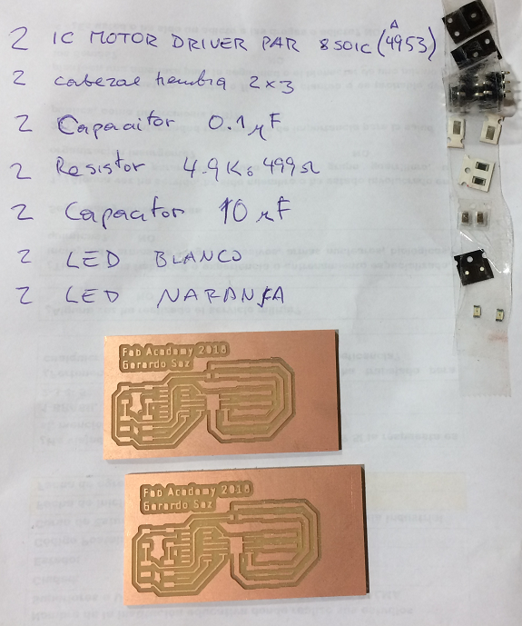
Here is the list of components for the PCB that will control the hard drive motor.
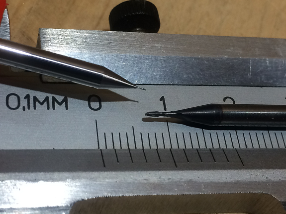
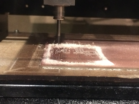
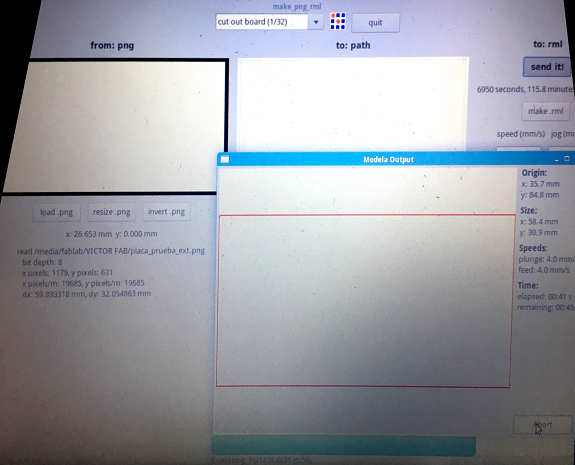
To mill the tracks the PCB used the milling bit of 0.01 "and for the cut the 1/32"
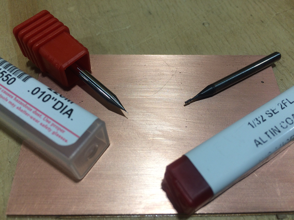
In this photo you can see the thickness difference between both drills.
Problem
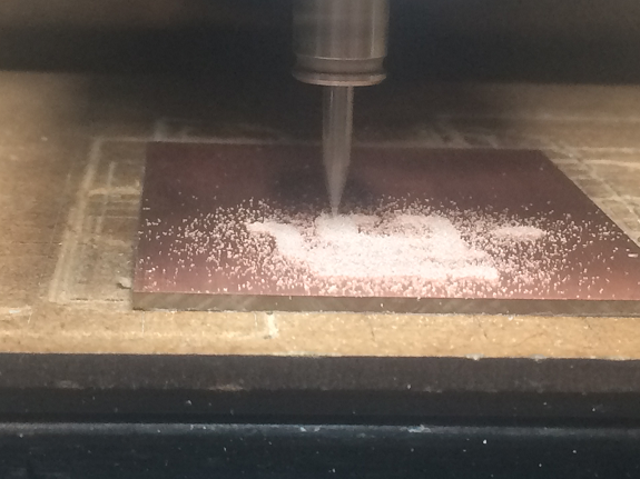
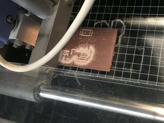
The bit broke in the middle of the job. I think it broke because I was milling very superficially.
Solution
Remove PCB and drill, when calibrating the point of contact of the bit with the PCB, I will give it a point further down.
The bit broke in the middle of the job. I think it broke because I was milling very superficially.
Solution
Remove PCB and drill, when calibrating the point of contact of the bit with the PCB, I will give it a point further down.
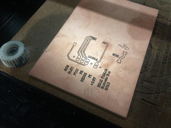
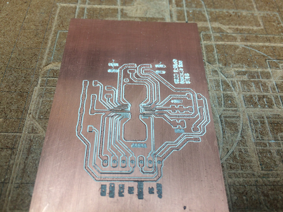
I re-milling the PCB, this time there were no problems.
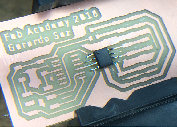
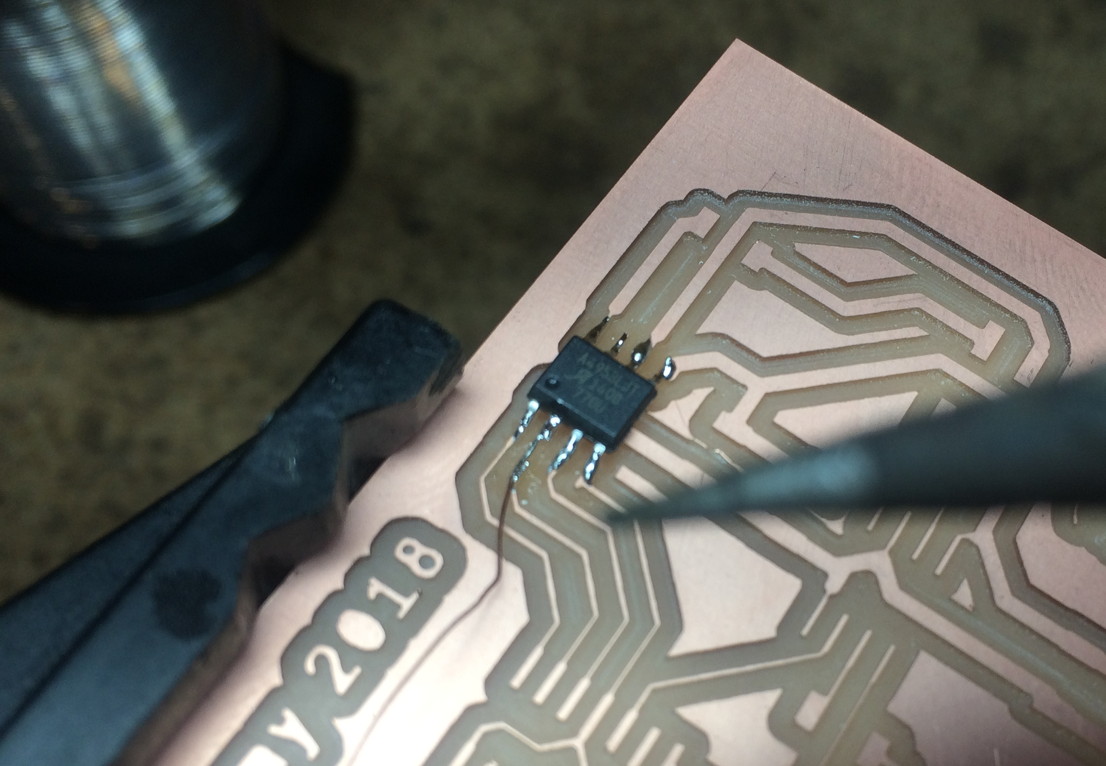
It was the first time that I soldered a controller with a heatsink and thought it was the best to protect myself from the heat to make sure that the heat can be dissipated.
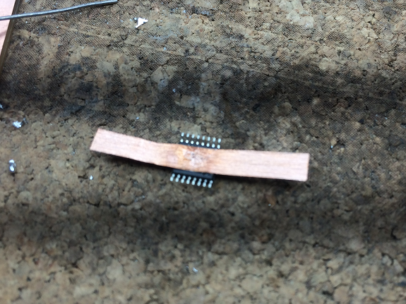
With that copper tape it was easier to place the controller in its place to be able to weld it.
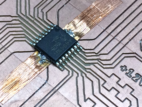
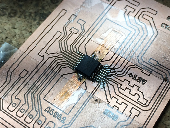
In these images, I welded the controller and added tin to the sides to help with heat dissipation.
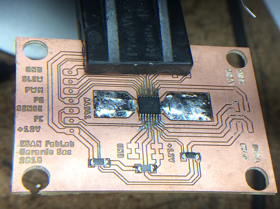
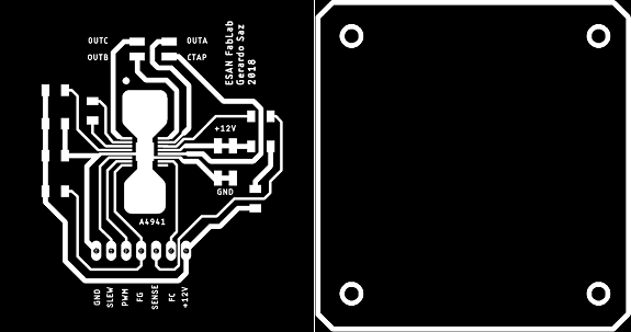
In these images I already have the PCB finished.
Video
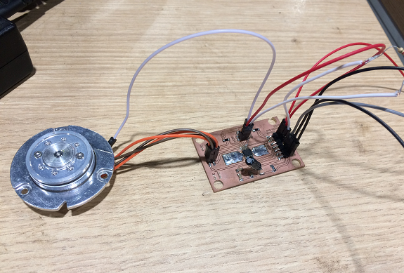
Test of operation of the motor controller with A4941 processor
But, no work !.
Test of operation of the motor controller with A4941 processor
But, no work !.
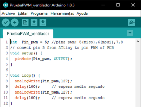
File to download
 TestPWM_propeller.ino
TestPWM_propeller.ino
As it did not work and I still felt that I was missing information from the A4941 controller, I decided to make a different PCB.
Motor Controller H-bridge
For my final project I need a couple of H-bridge drivers for the left and right wheels.
For this I used the example of Neil: hello.H-bridge.44 in the section "DC motor H-bridge".
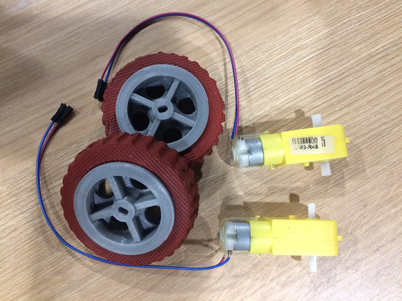
In the image I show the tires made in the assignment "Molding and Casting" and rims manufactured in 3d printer, both I designed them in Rhinoceros and Grasshopper.
In the image I show the tires made in the assignment "Molding and Casting" and rims manufactured in 3d printer, both I designed them in Rhinoceros and Grasshopper.
This board carries the controllers ATtiny44 and A4953 which is responsible for the H-Bridge.
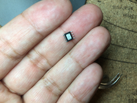
In this image I have in my hand an A4353 driver , it measures 4.9mm
In this image I have in my hand an A4353 driver , it measures 4.9mm
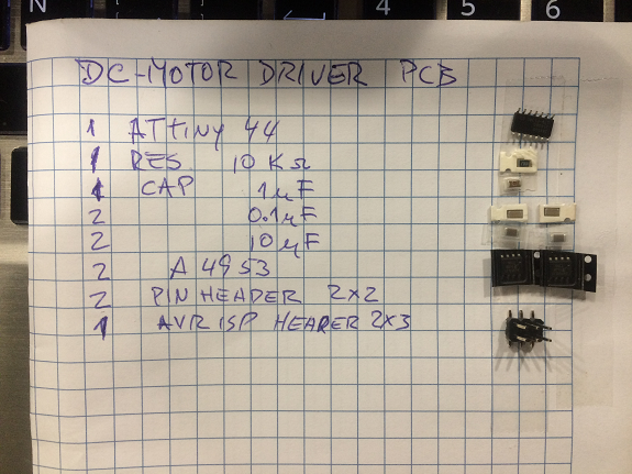
This is the PCB of the example (link to page), , from it I extracted the follow list of components.
- 1 ATtimy44 microcontroller
- 1 A4353 motor DC driver
- 2 Capacitor SMD 1uF
- 1 Capacitor SMD 10uF
- 1 Resistor SMD 10kΩ
- 1 Voltage regulator 5V
- 1 6-pin header
- 2 4-pin header
- 3"x 2" PCB board
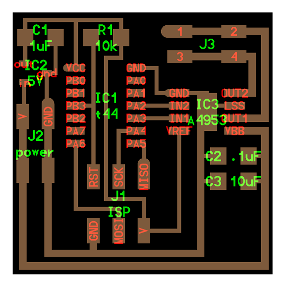
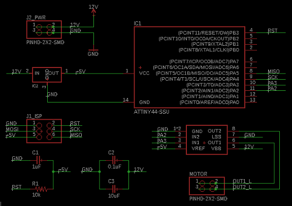
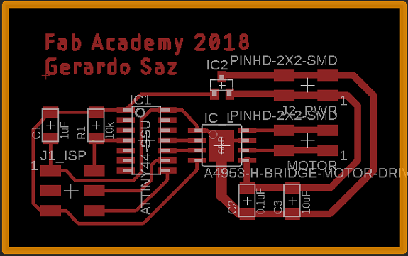
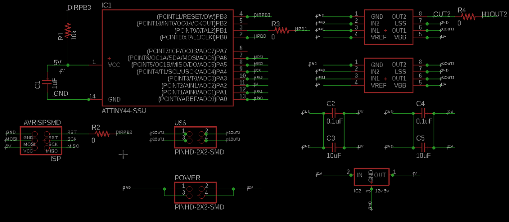
To make the PCB I used Eagle, here I show the schematic diagram, with all the components, their values and the connections between them.
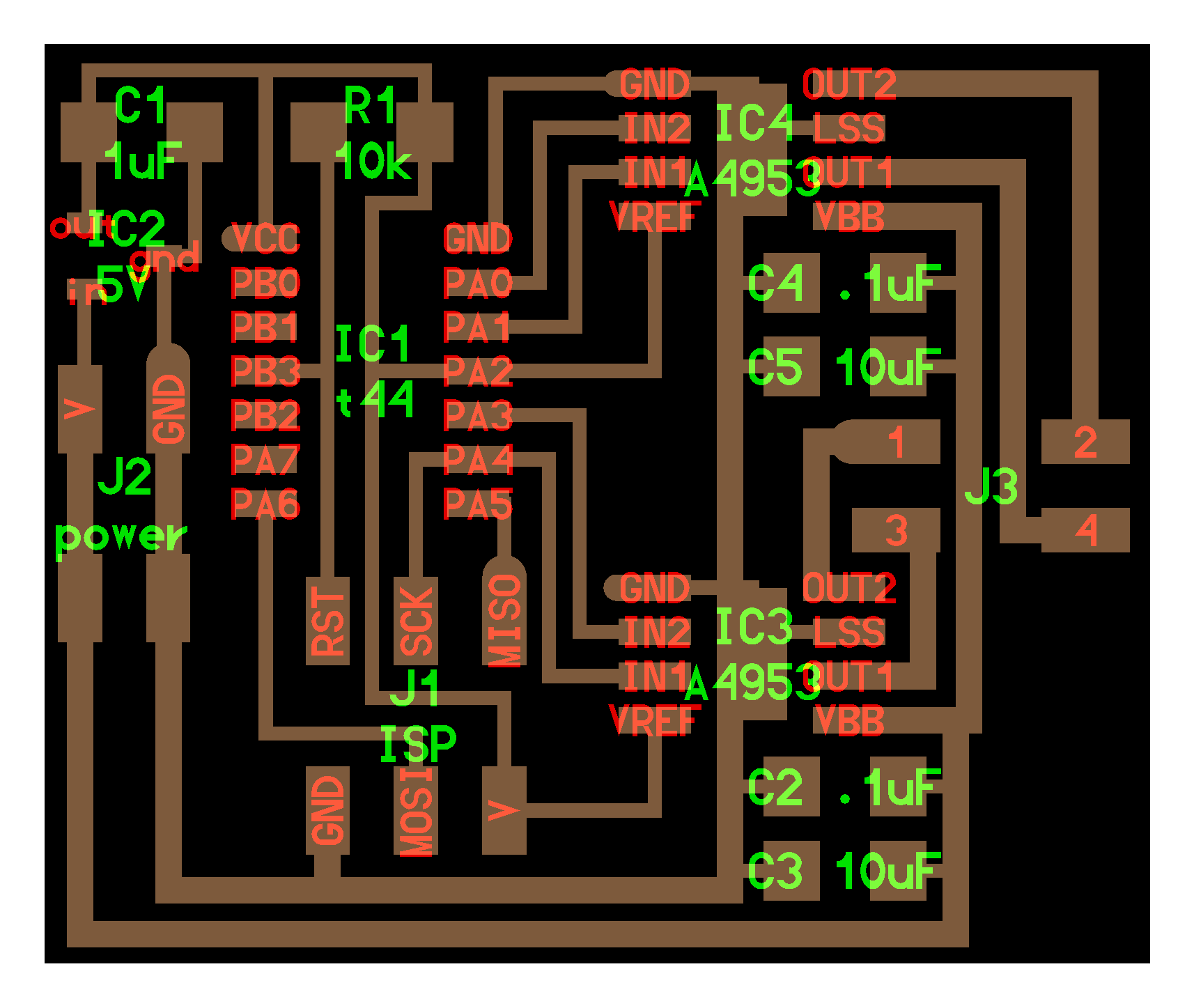
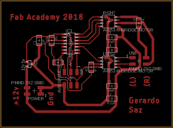
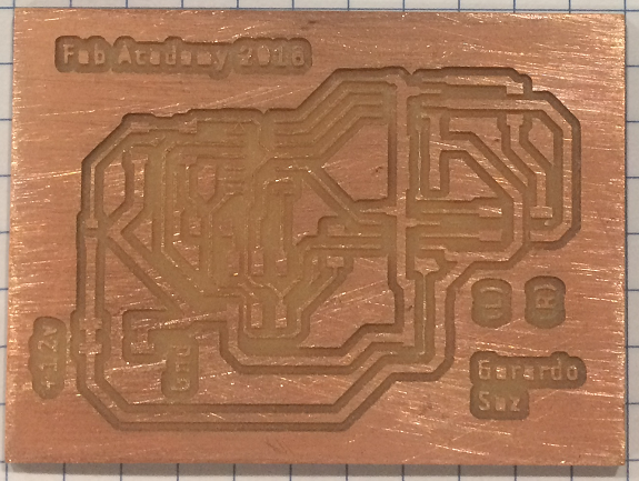
After accommodating all the components keeping the routes as short as possible and the components not so close that it is difficult to weld, nor so separated that the PCB is very large, I obtained the PCB, there was some space left for my name.
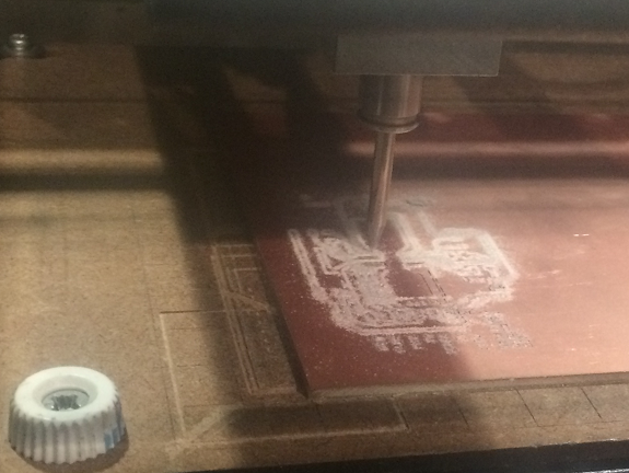
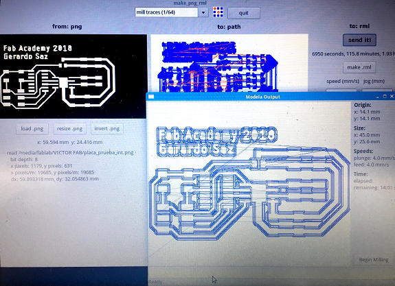
The milling process in Modela 20 lasted 1 hour.
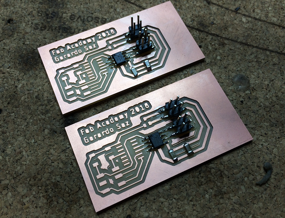
This PCB can only control one motor, so I milled a second plate.
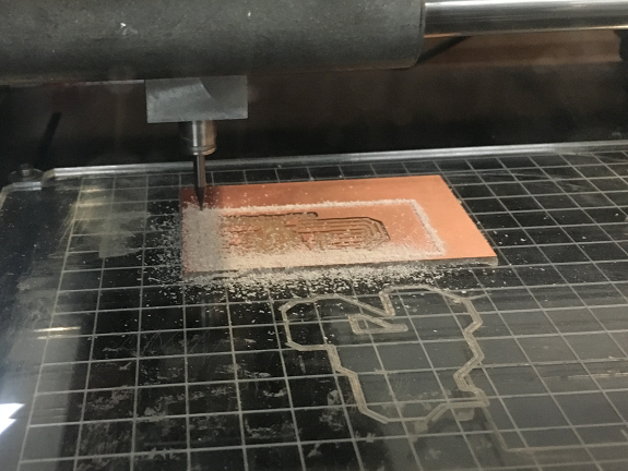
This PCB is one of the newly milled plates, it is ready to weld the components.
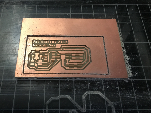
Ready to start the process of welding components.
I connected one of the PCBs to my FabISP programmer and this in turn to my laptop to load the program.
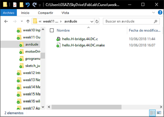
These are the files of Neil's example.
Fabacademy's archive
Files for download
hello.H-bridge.44.DC.c
hello.H-bridge.44.DC.make
Files for download
hello.H-bridge.44.DC.c
hello.H-bridge.44.DC.make
Error
These PCBs do not have FTDI, the communication is by ISP, so I used my FabISP burner to load the test program, but I could not, I do not know what is wrong, an error occurs in the code.
gsaz@TOSHIBA:/mnt/c/Users/GSAZ/Output$ ls
hello.H-bridge.44.DC.c hello.H-bridge.44.DC.make
gsaz@TOSHIBA:/mnt/c/Users/GSAZ/Output$ make -f hello.H-bridge.44.DC.make program-usbtiny
hello.H-bridge.44.DC.make:10: *** missing separator. Stop.
gsaz@TOSHIBA:/mnt/c/Users/GSAZ/Output$
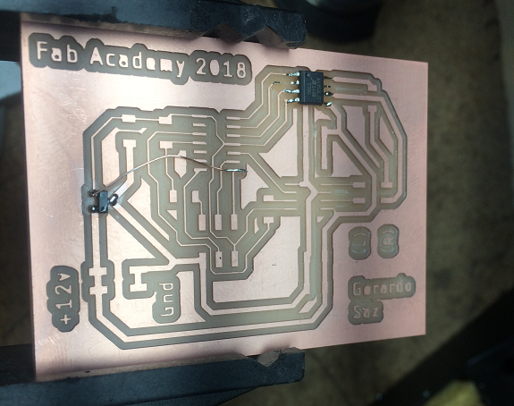
I looked for the fault and found one of the tracks of ISP without doing, to prove that the fault was due only to that, I soldered a copper wire to the contacts of the ISP and the pin 7 MOSI.
I tried again, but the error continues.
So I had no other way out than to do the PCB again, from the design using Eagle.
I tried again, but the error continues.
So I had no other way out than to do the PCB again, from the design using Eagle.
Stepper Bipolar Motor Controller
This time I based another example of Neil, Stepper Bipolar Motor, which has two A4953 with separate outputs, so with them I can control two gear motors.
This time I based another example of Neil, Stepper Bipolar Motor, which has two A4953 with separate outputs, so with them I can control two gear motors.
This is the schematic diagram made with Eagle, from Neil's example.
Then, I arranged the components and traced the tracks, I made the GND tracks wider.
This is the new milled PCB.
This is the list of components to weld.
Another obstacle
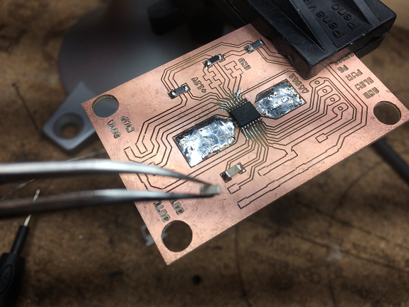
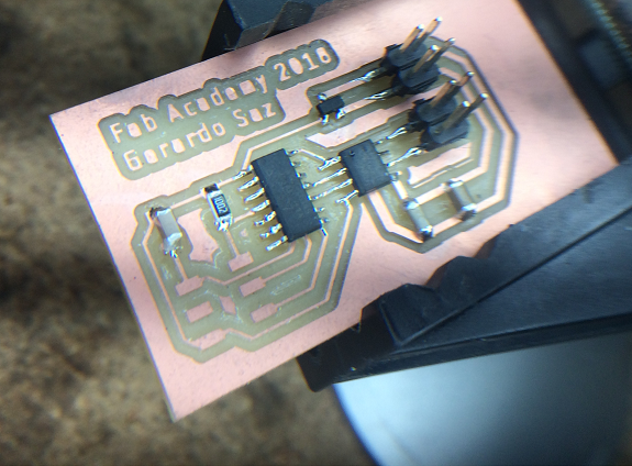
The track that reaches pin 2 of ATtiny44 was very thin and broke.
The track that reaches pin 2 of ATtiny44 was very thin and broke.
To repair it I used a piece of copper wire, it was very good.
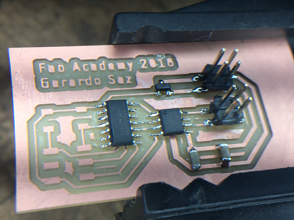
This is the Stepper Bipolar Motor PCB.
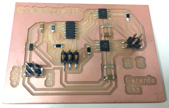
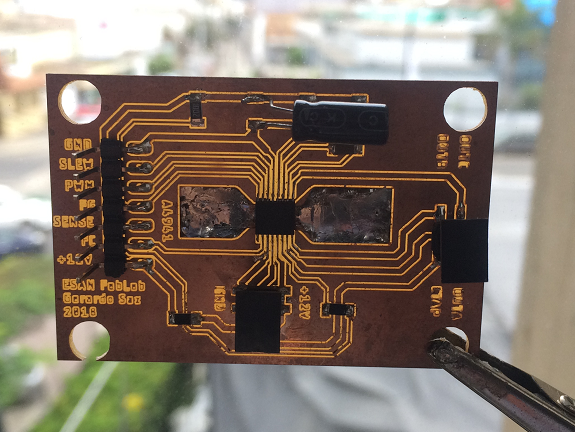
As you can see in my component diagram, the microcontroller of the right motor is on the upper side of the PCB and the microcontroller on the left side of the central side.
According to my schematic diagram, the right motor microcontroller is connected to pins # 13 and # 14 of the ATtiny44. While in the case of the left motor microcontroller are pins # 10 and # 3.
I made this table by combining the above information with the Pin of the ATTiny44 microcontroller.
According to my schematic diagram, the right motor microcontroller is connected to pins # 13 and # 14 of the ATtiny44. While in the case of the left motor microcontroller are pins # 10 and # 3.
I made this table by combining the above information with the Pin of the ATTiny44 microcontroller.
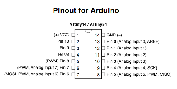
| Motor | #Pin | Description | Arduino |
|---|---|---|---|
| Right | 13 | PA0 | 0 |
| 12 | PA1 | 1 | |
| Left | 10 | PA3 | 3 |
| 3 | PB1 | 9 |
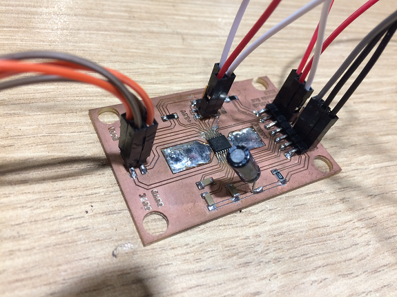
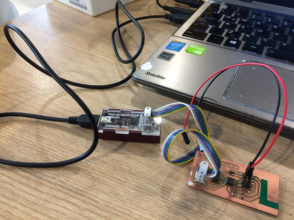
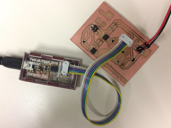
It's time to upload the program. for that I used my FabISP programmer and some cables to give 12 volts to the PCB.
This time, there were no problems, everything was loaded and suddenly the engines started to work.
This time, there were no problems, everything was loaded and suddenly the engines started to work.
Programming the microcontroller
Video Test