Week 2 (Computer-Aided Design)
Part1: Model (raster, vector, 2D, 3D, render, animate, simulate, …) a possible final project, Part2: compress your images and videos, and Part3: post it on your class page
Part1: Model (raster, vector, 2D, 3D, render, animate, simulate) a possible final project
For 3D modeling I use parametric design software called Grasshopper. I started modeling three curves in the rhino front view because I need to transform with nurbs points.
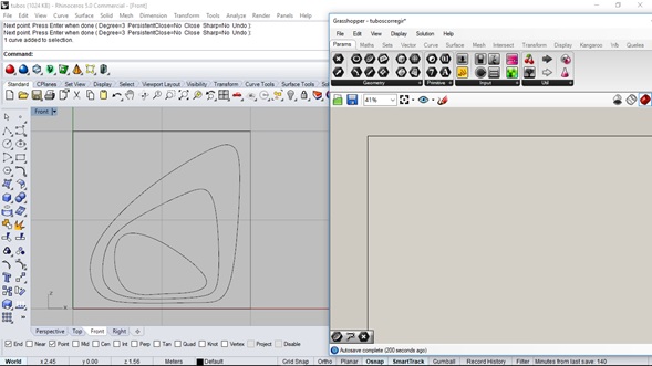
Once the curves were moved in space I sent their information to Grasshopper using the Curve component, with "Set one curve" command, and after that pick the curve
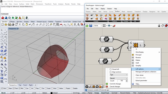
Using the loft component I've made the parametric surface geometry that allows faster prototype creation.
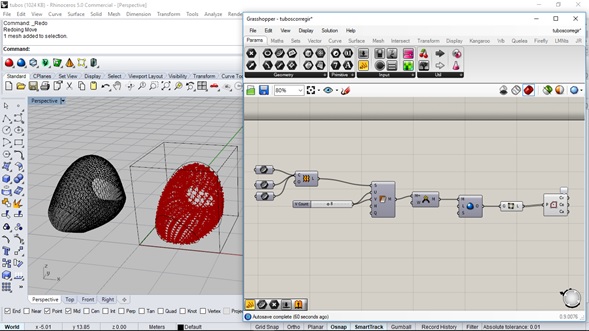
The surface was transform to mesh. The mesh allows work with building units to create a skin with the mesh shape, it was possible with weavebird components.
Other options of defining the surface as a function of a pattern were tested, so a box pattern was used that allows defining the surface as a function of the nurbs geometry and not on a mesh.

Develop the module that allows the assembly of the connectors, was defined from a triangle that generates the intersections of three extrude circles in space.

+

+

The parametric definition of the pattern was used to complement the division of the surface and to have an idea of its distribution in space

2D Software-(AutoCad Civil3D)
For 2D software, I've started configuring Autocad to modeling
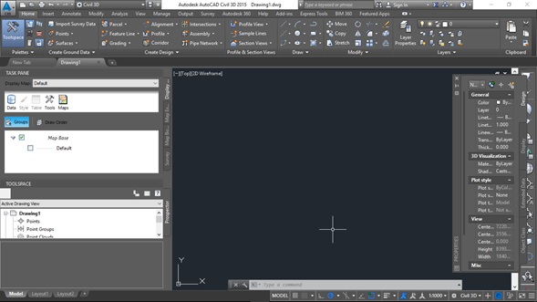
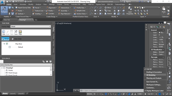
Once in the modeling environment, Autocad allows to make special tools only available in 2D drawing mode and modeling
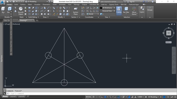
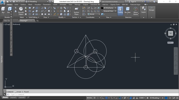
The profile of the form was started as a function of the center of an equilateral triangle. Tangent arcs were generated to join the circles results of joining vertices with midpoints of the opposite sides.

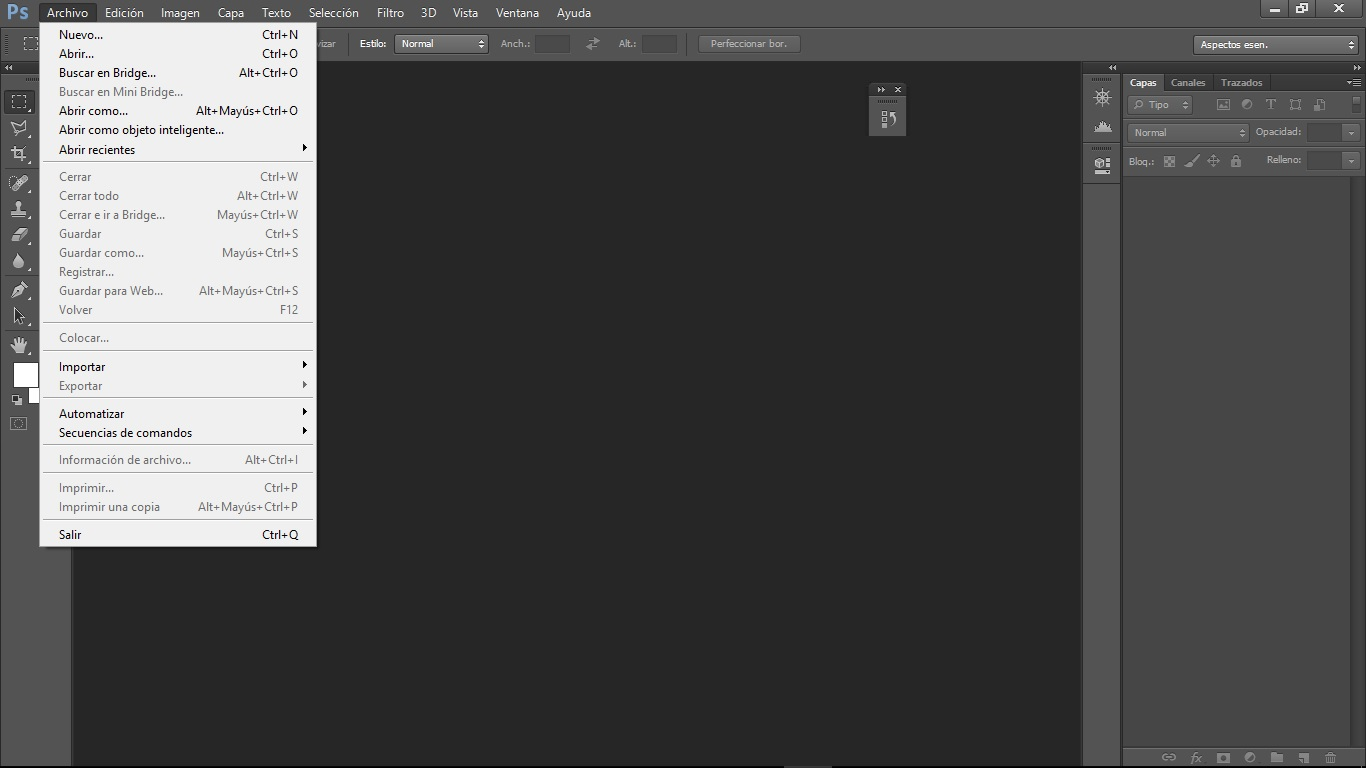
For 2D Raster Design Software I used Photoshop
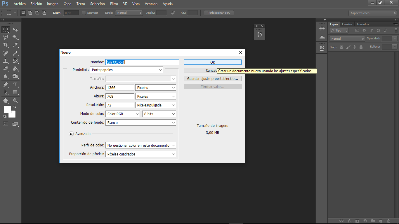
we have to create a new file, for that we go to the new menu -> file, in the options window We choose the name and the dimensions of the design canvas
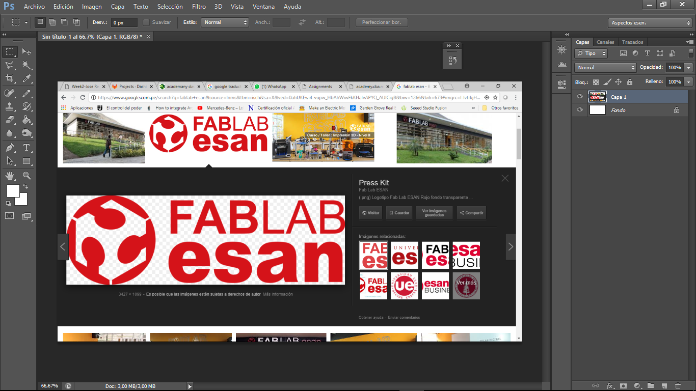
Paste an image
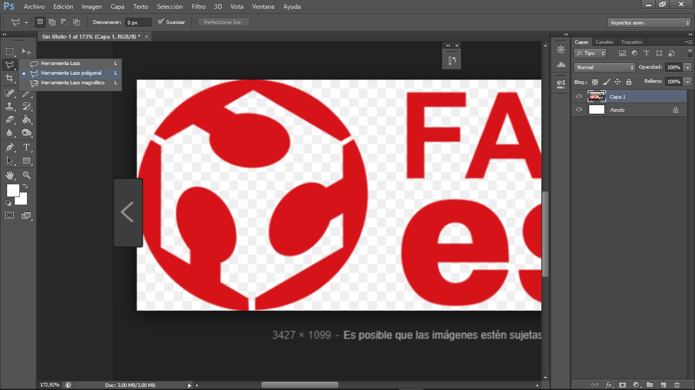
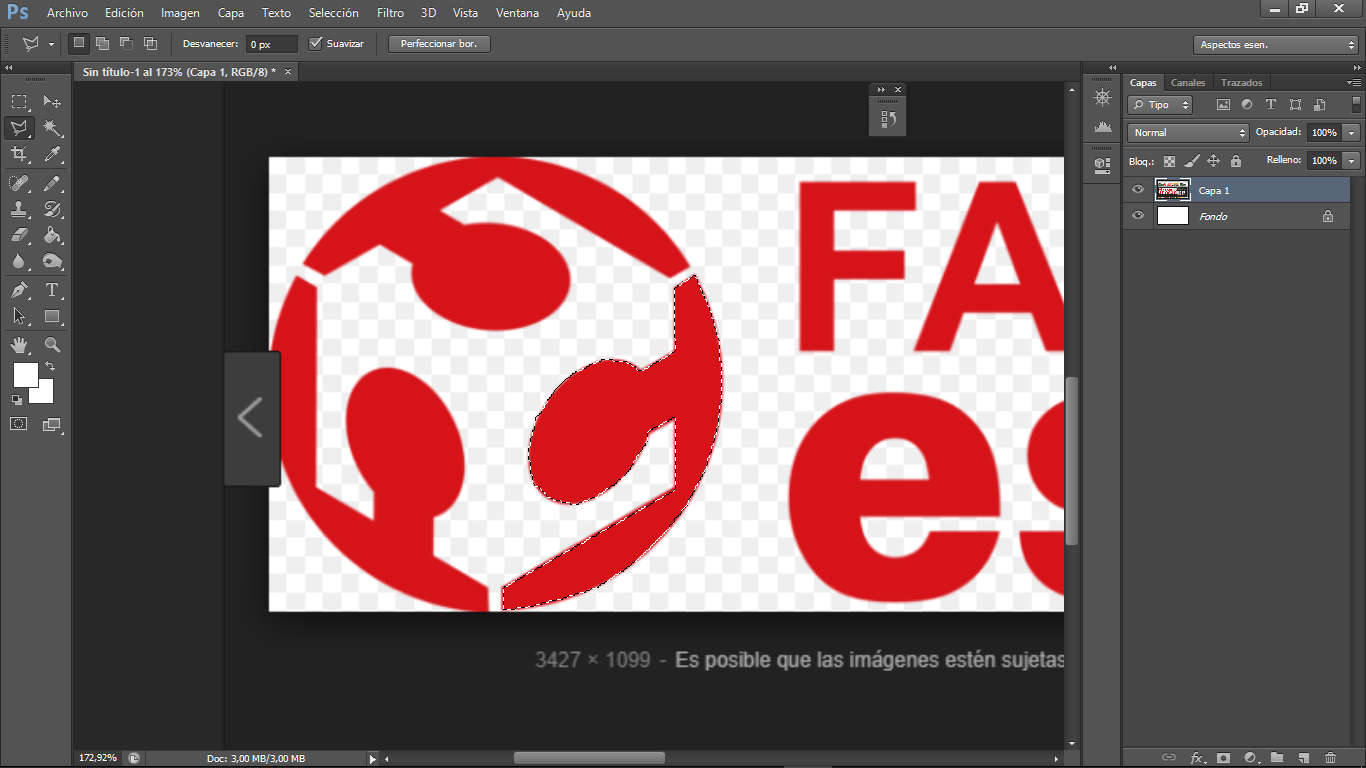
choose the polygonal lasso tool and select what we need from the reference image
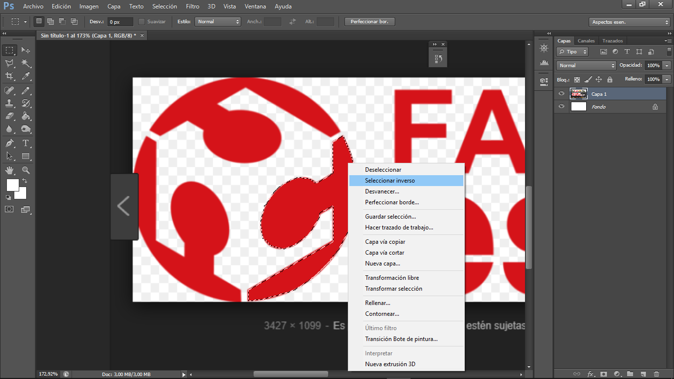
Choose the reverse select tool to erase everything we do not need
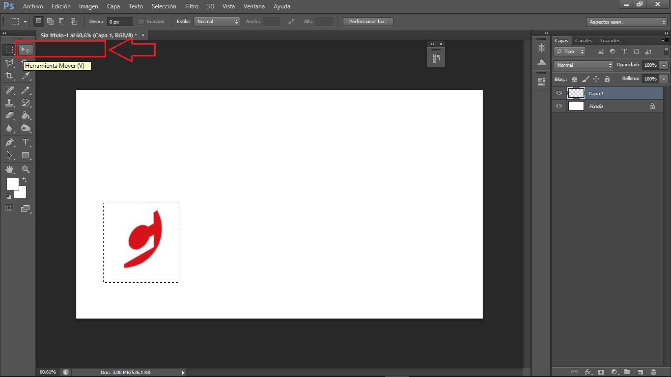
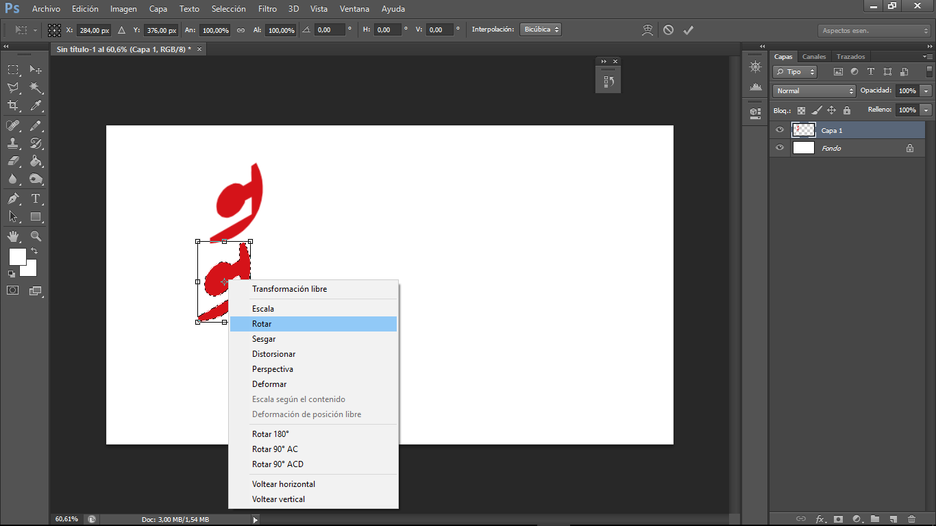
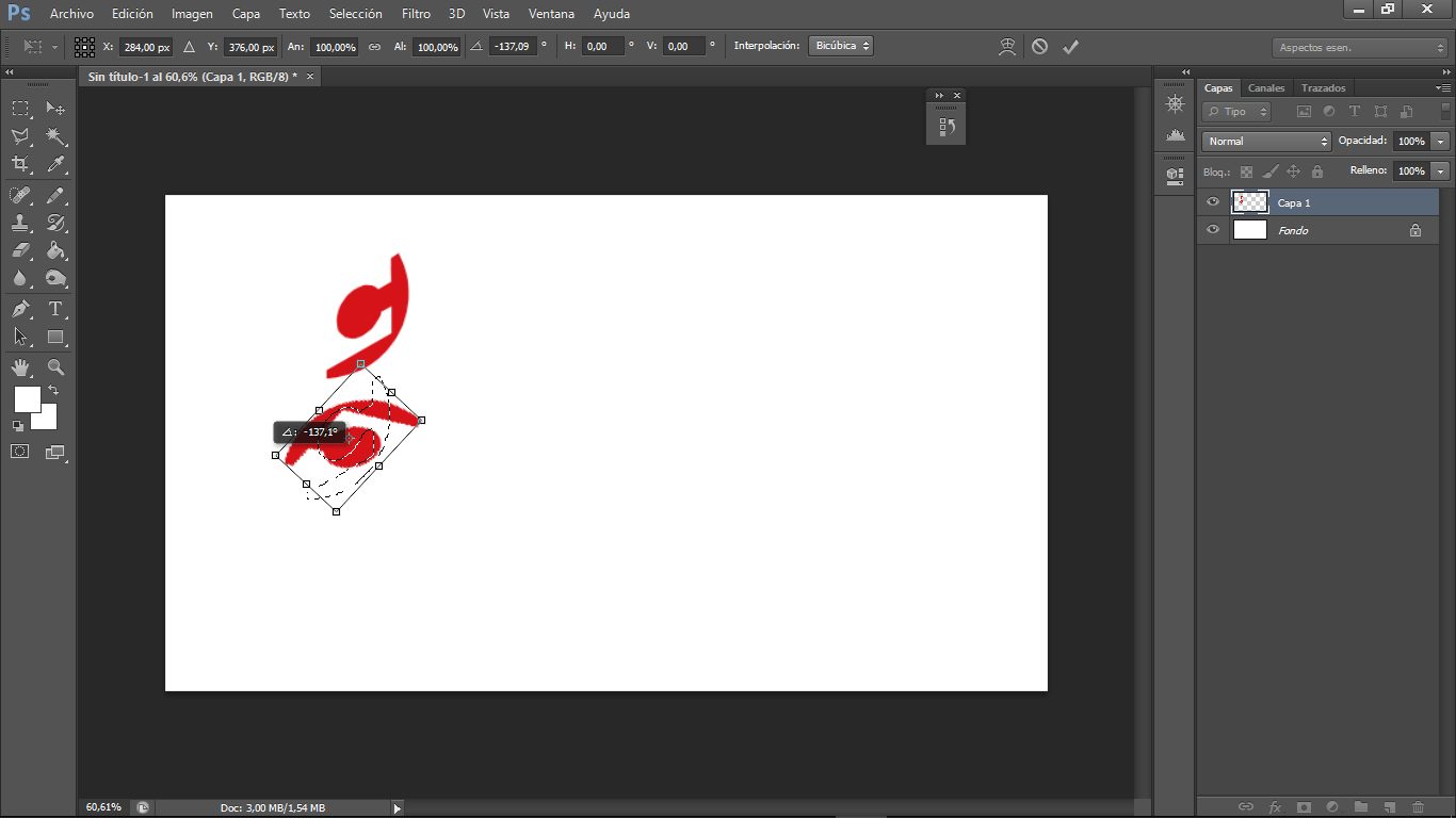
We begin to transform and copy our selection according to the design we want to achieve. To copy press the Alt key and to transform we have to have selected the zone that we want and with right click we choose the type of transformation that we need
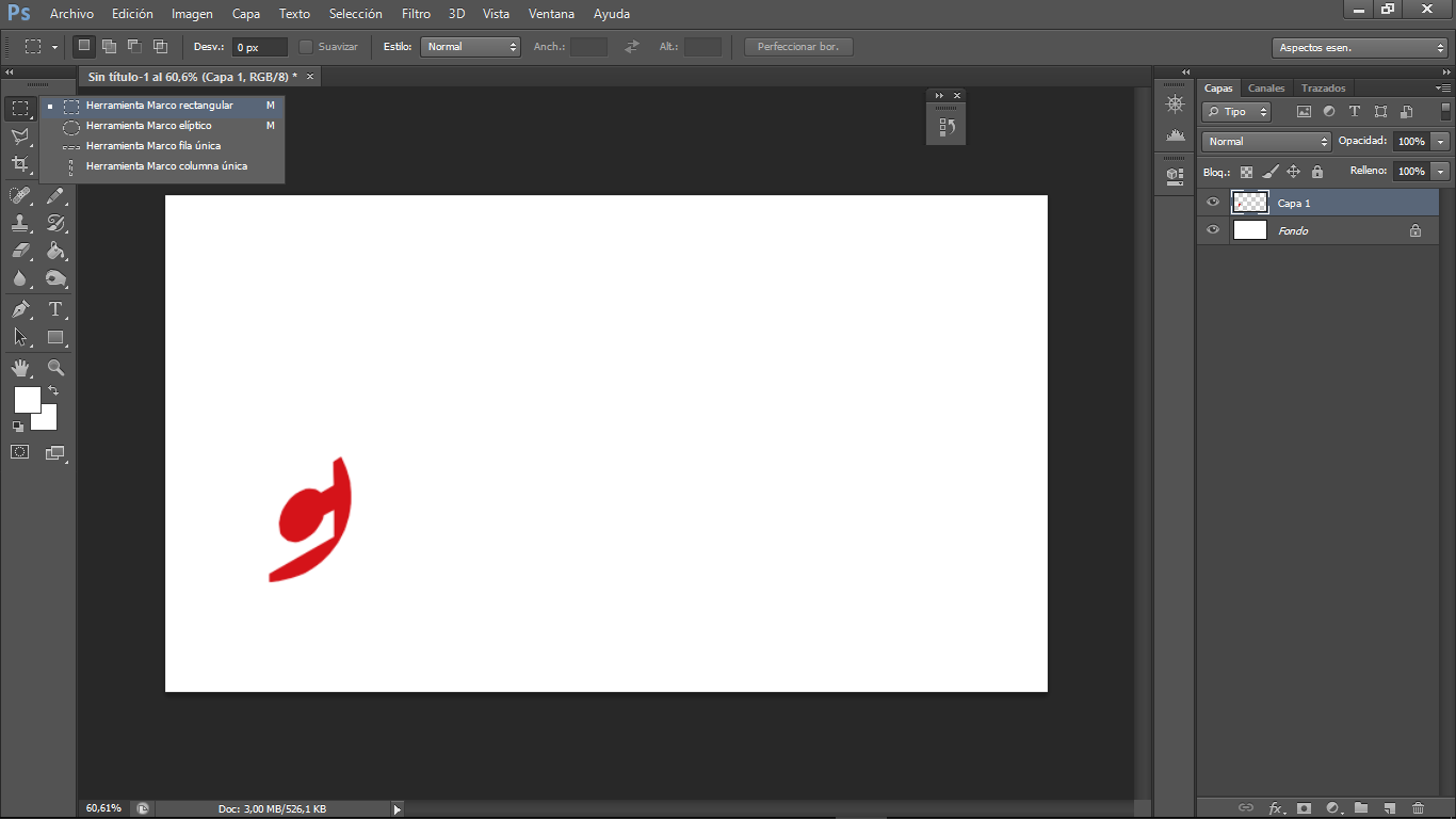
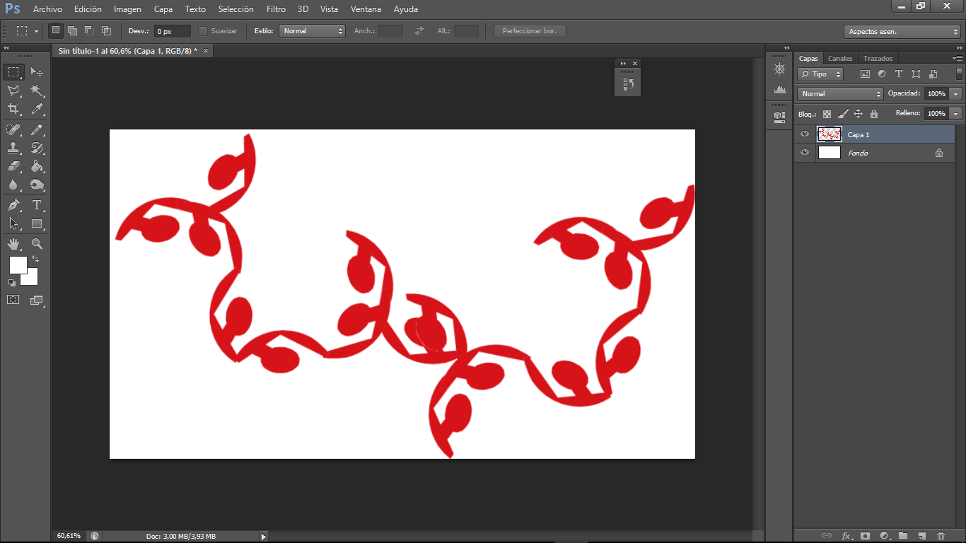
I've selected the previous form to copy and create new patron

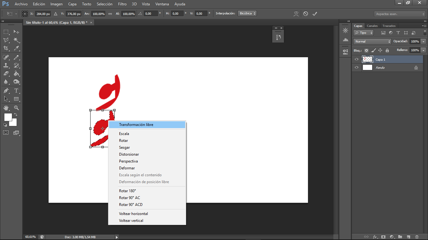
we can compose with this simple technique and if we need to export we go to the option to save as and there we can use the form
Part2: compress your images and videos
To compress the images in format png and jpg I use the ffmpeg command line software
After the installation process I leaved to ffmepg folder unpacked to copy my images and I used the following process to compress:
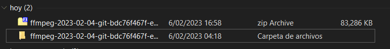
After the download process we have to uncompress the folder
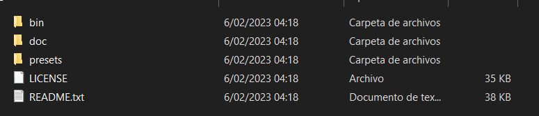
We have to leave to the bin folder into the ffmpeg folder
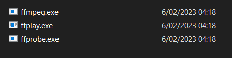
Inside the bin folder we have the .exe file, it means when we want to run the program we have to use the windows command line or "cmd"
Inside the cmd command line we have to located into the folder that contains the .exe file
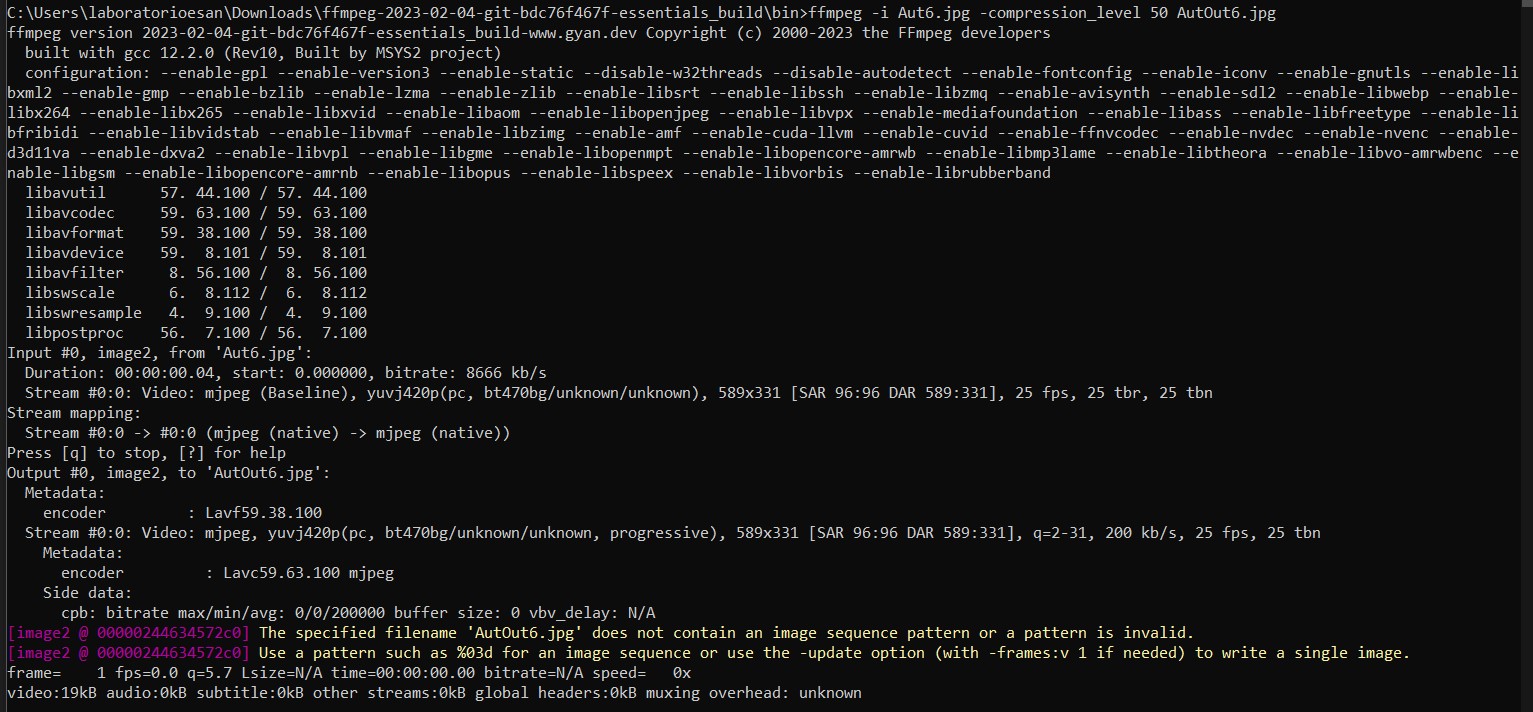
The final command that I used is: ffmpeg -i ffmpeg3.jpg -compression_level 50 ffmpeg3Out.jpg
Part3: Simulate
To simulate the forces that work into the join, I used SimScale to perform a simulation
The first step is Sign Up with a account creation there is a free credits enought to make a simulation, this plattform has 3 different types of simulation. strutural, fluid, and thermal.
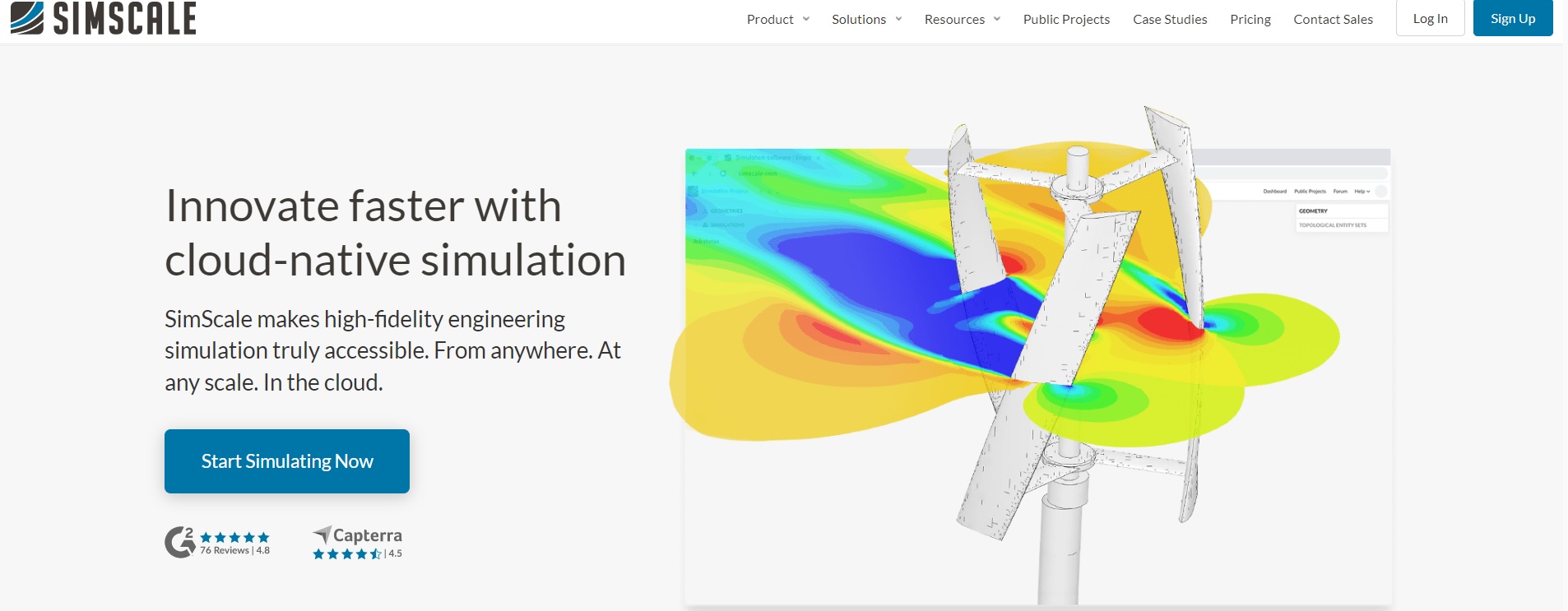
The Sign Up option in the top right side needs a google account to sign in
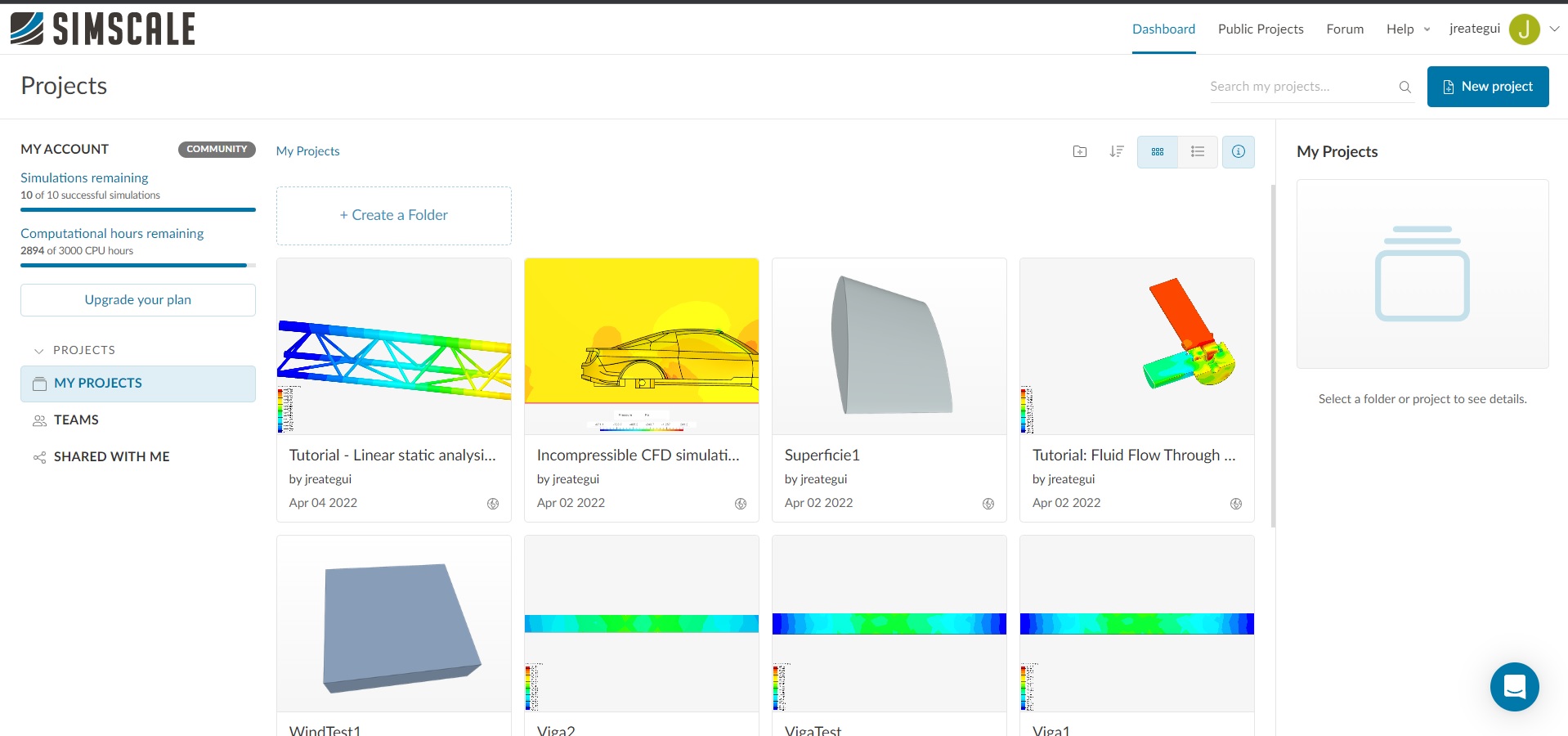
The first screen after sign in shows the recent project and in the right side there is a blue button: "New Project"
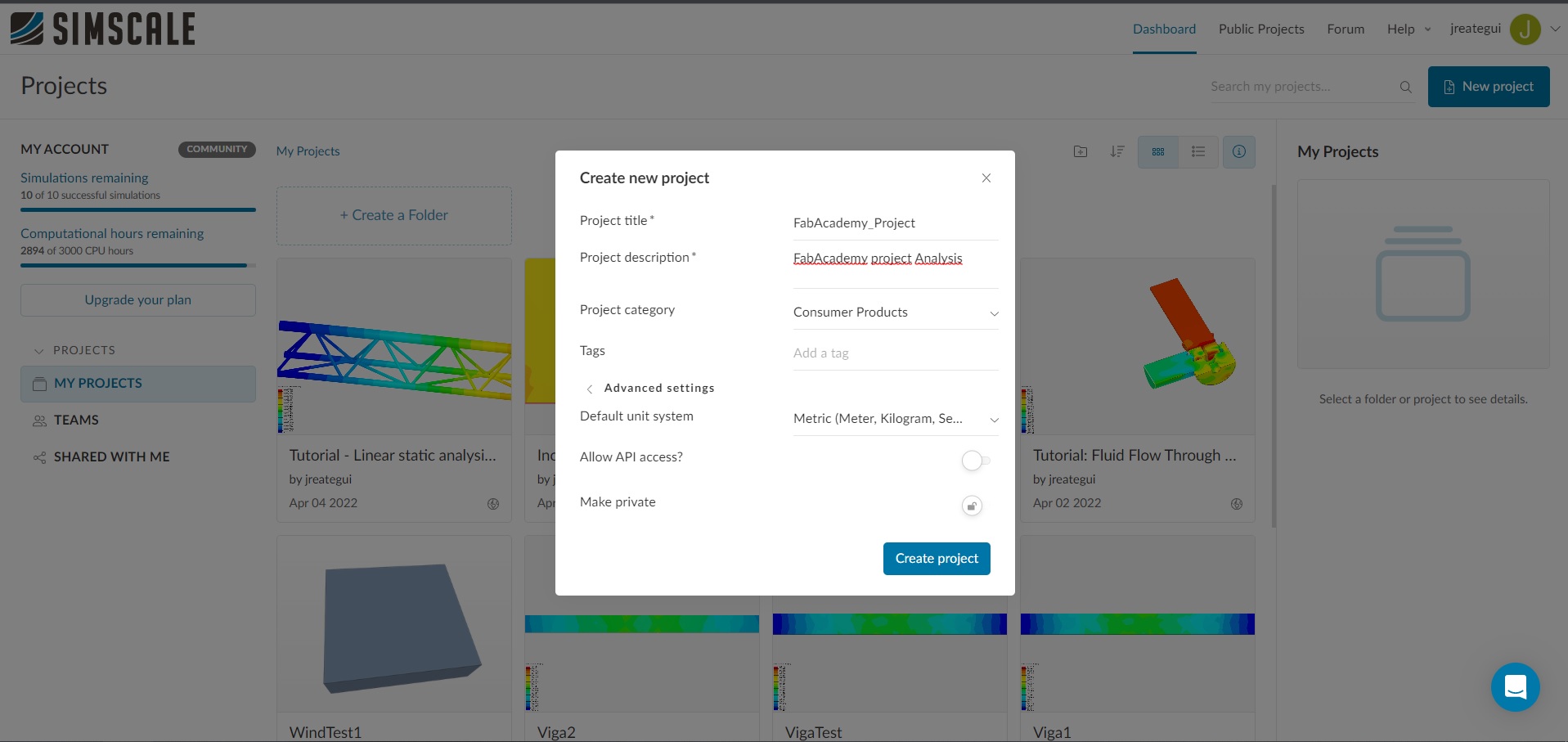
To make the project we have to complete the gaps: "project title" "project description"
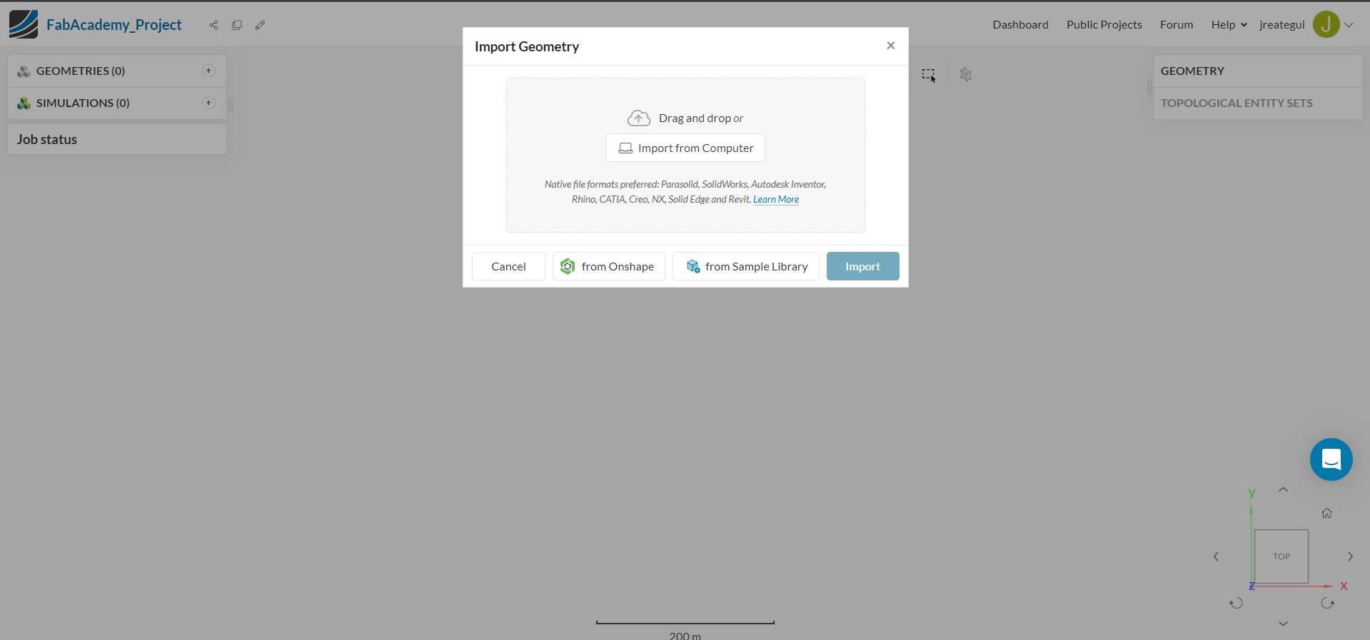
The next step is import the geometry, in my case I made the geomtry with Rhinoceros3D
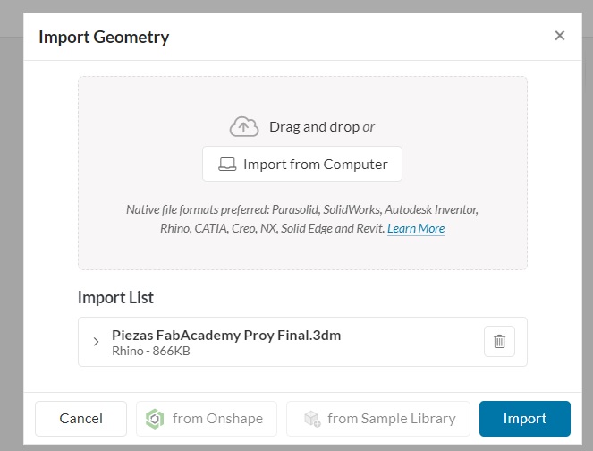
SimScale can import Rhinoceros3D files in 3dm format in native way
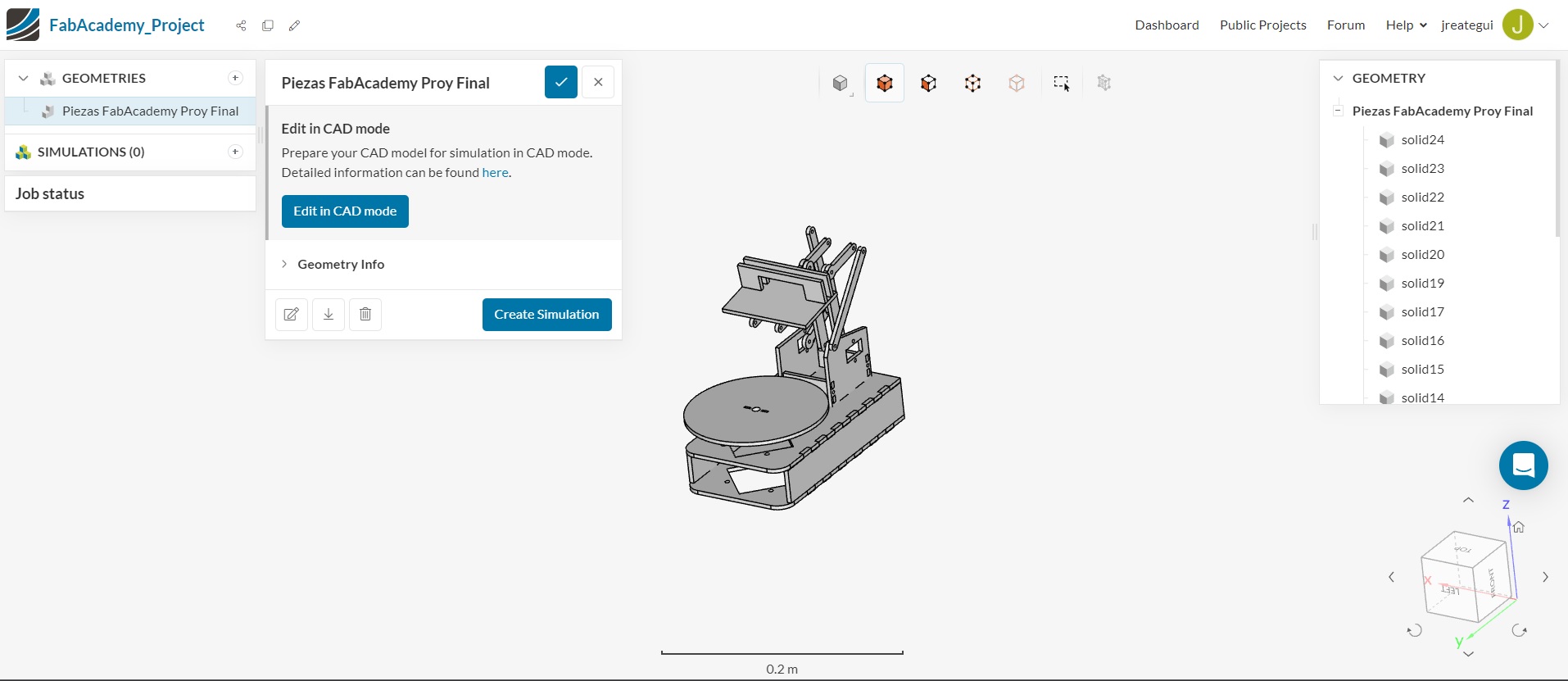
The import result shows the solid entity in the right side
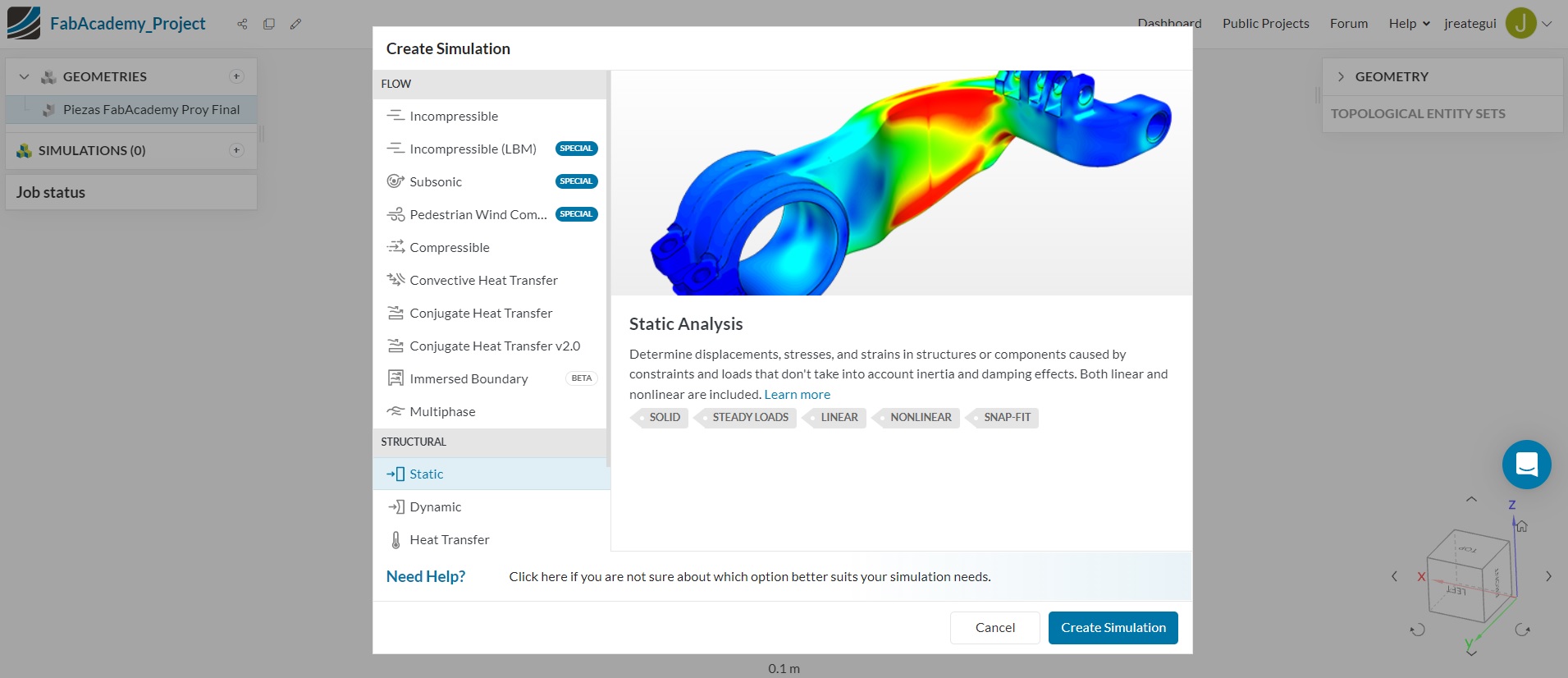
In the next screen I deciced to use the "Structural-Static" simulation in the left side with the butto "create simulation" in the right side
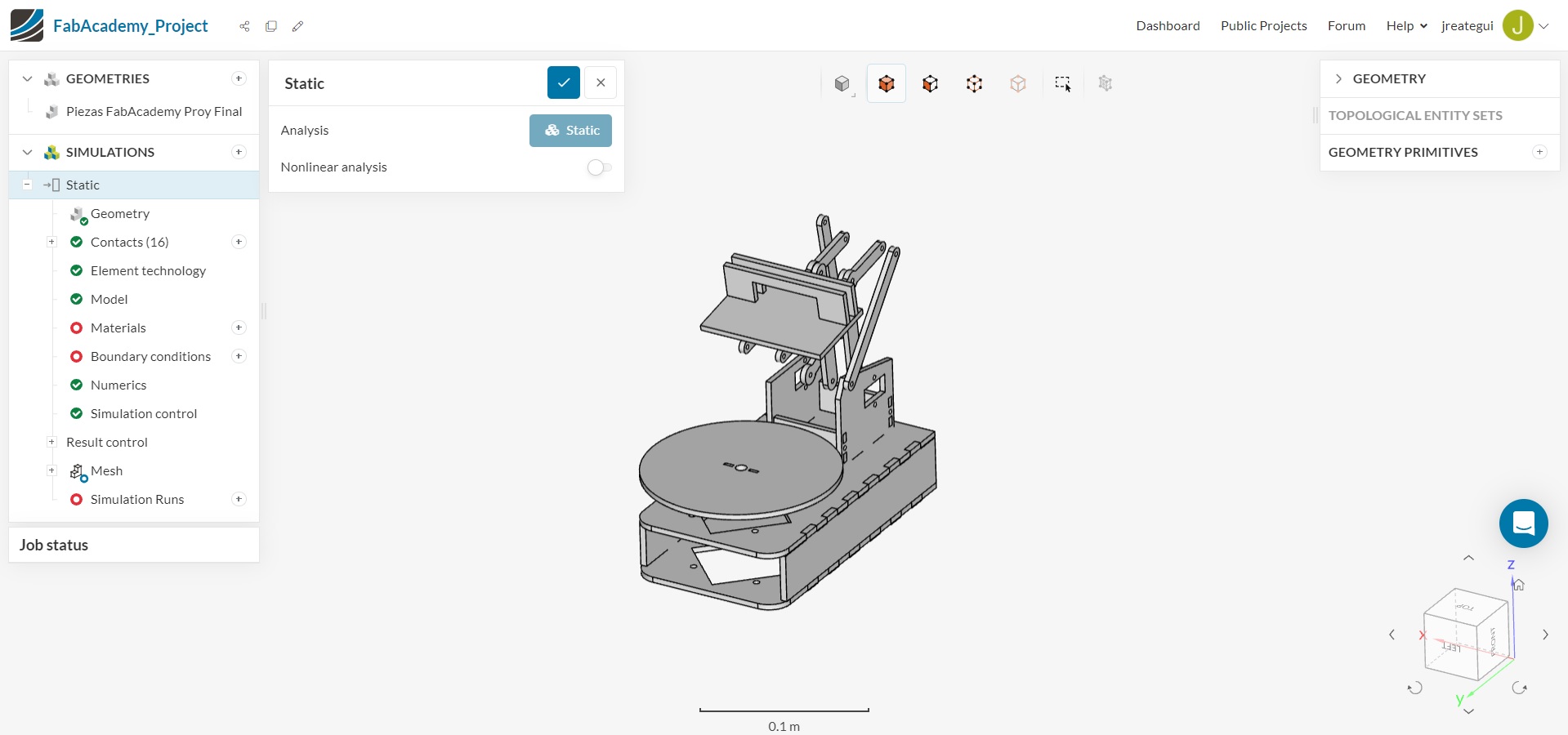
Then in the left side the software shows a process tree with geometries, simulations, the simulations consists in Geometry, contacts, element technology, and others options have a green check closer in the left side. But we have to solve the options with red color such as materials, boundary conditions, and simulation runs in the top down sequence
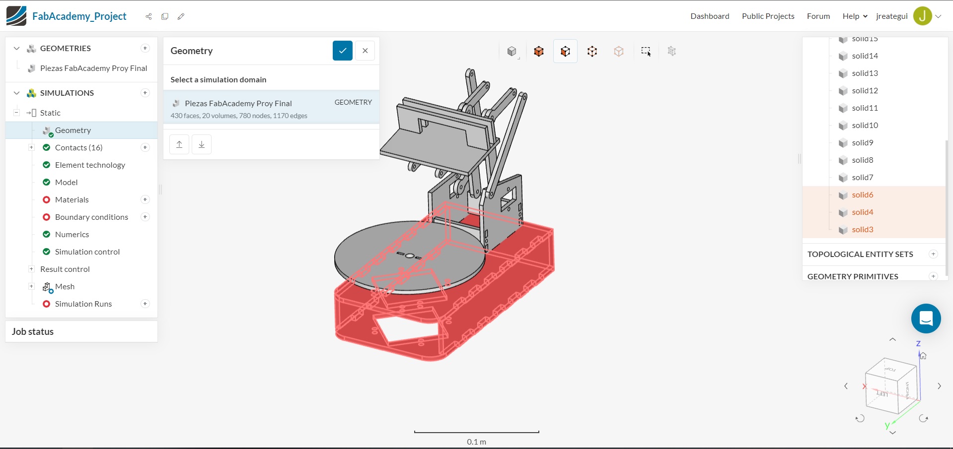
The first step is to select the geometry that we want to analyze
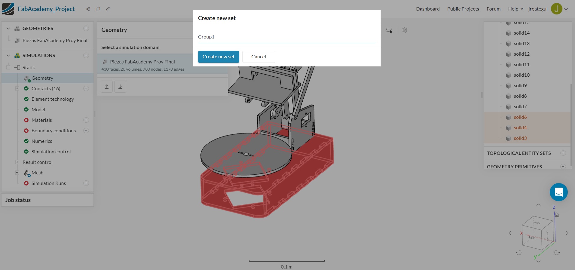
Is important to make a set with the geometry elements that we want to analyze
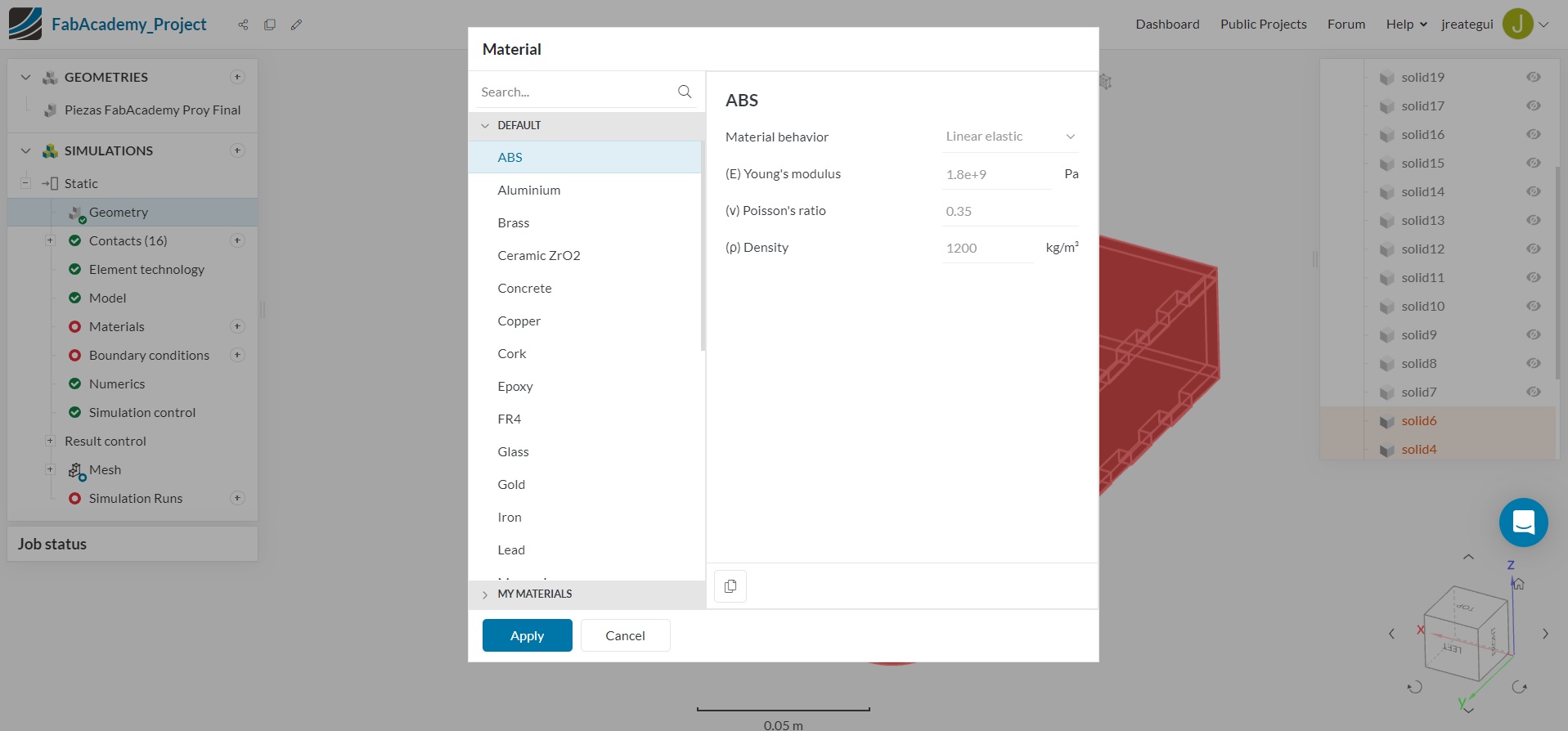
After that we have to define the material, in this case I choose wood beacuse the parameters is closer to MDF
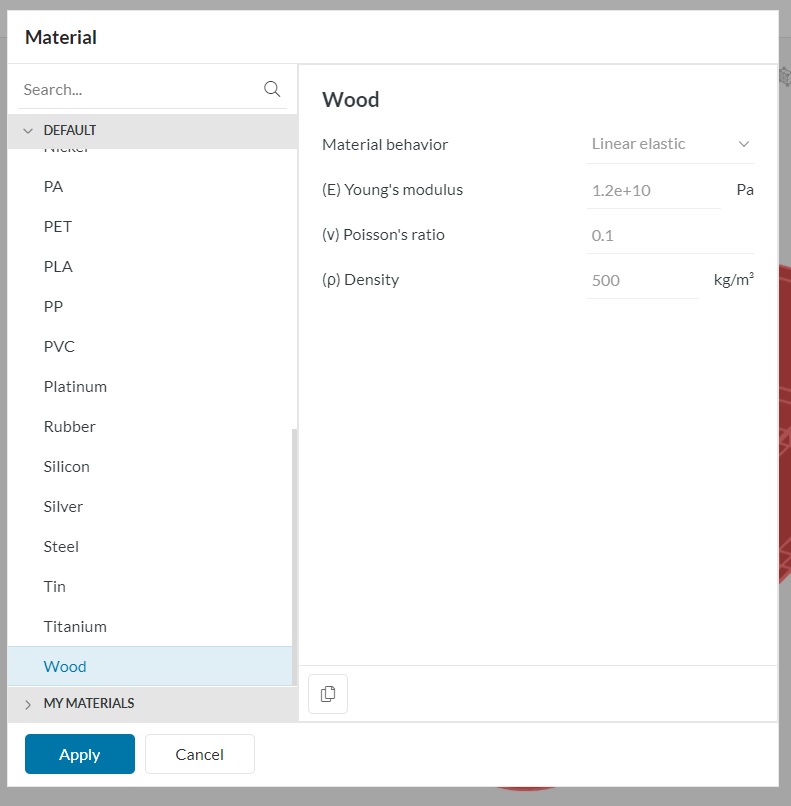
The wood material has the following parameters: Young's modulus, Poison's ratio, and Density
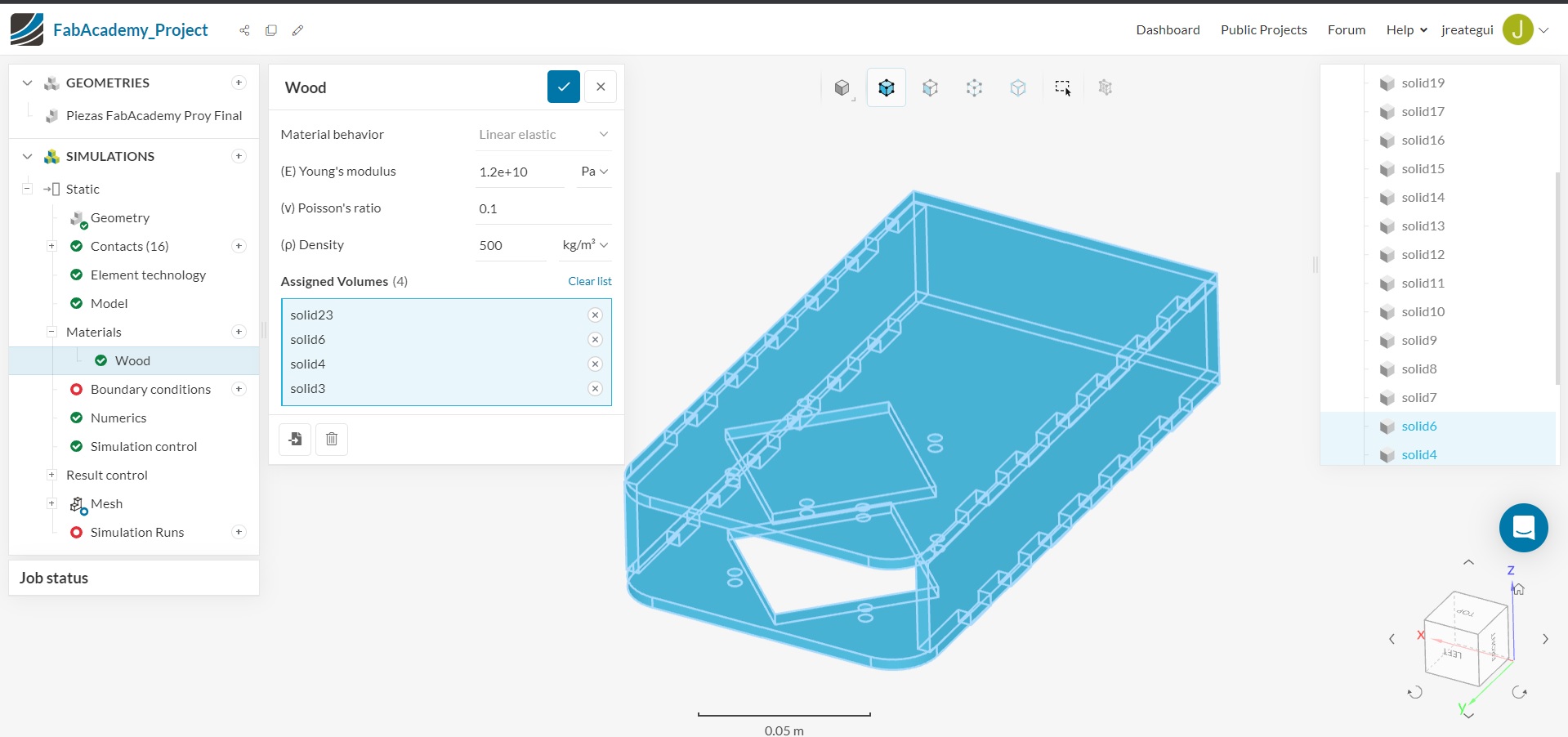
The wood material was assigned to geomtry set
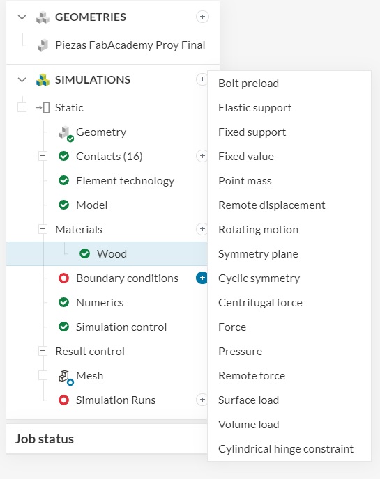
When the set had the material the next step consists in define the boundary conditions. First, the fixed support
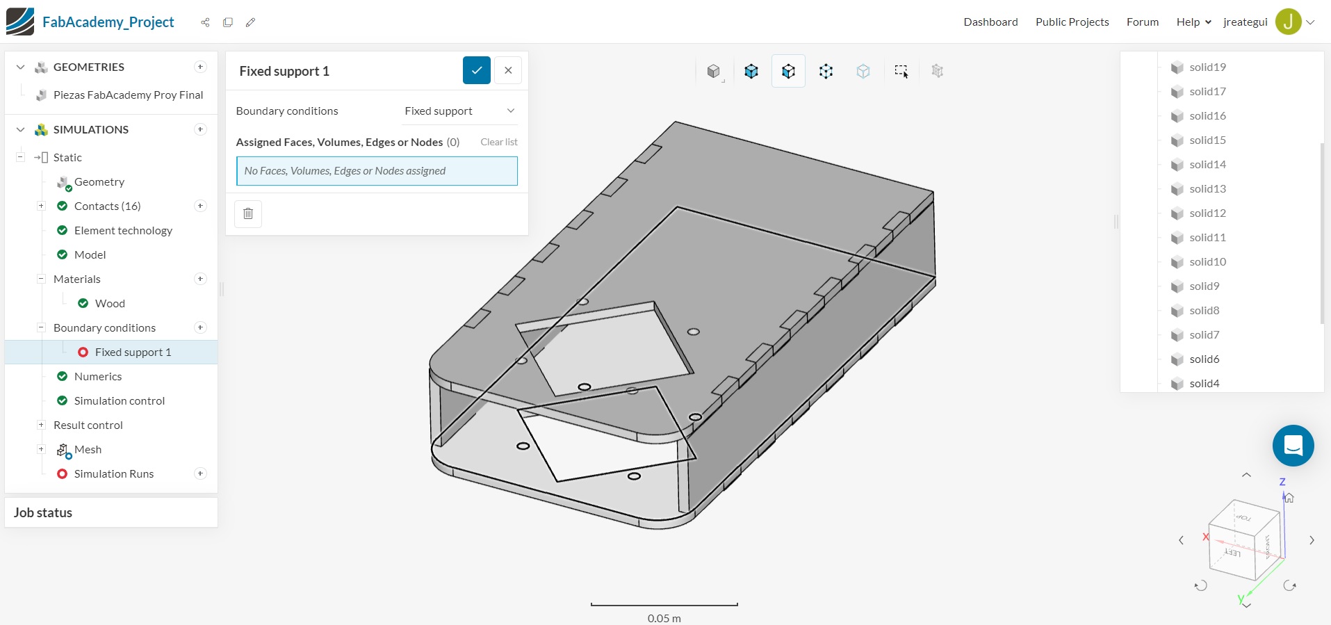
The fixed support needs to define with pick from user mouse
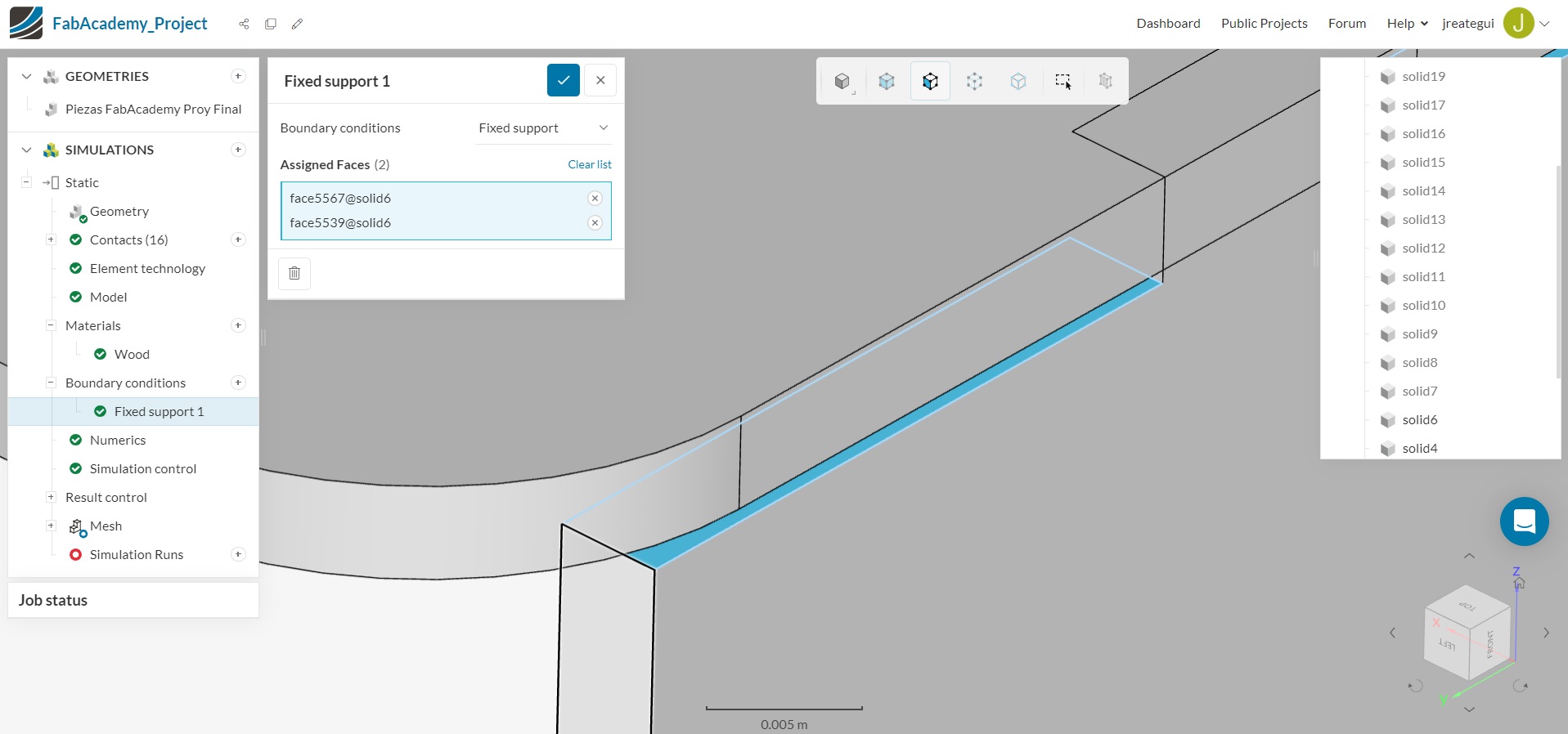
The fixed support in this case consists in the xy faces
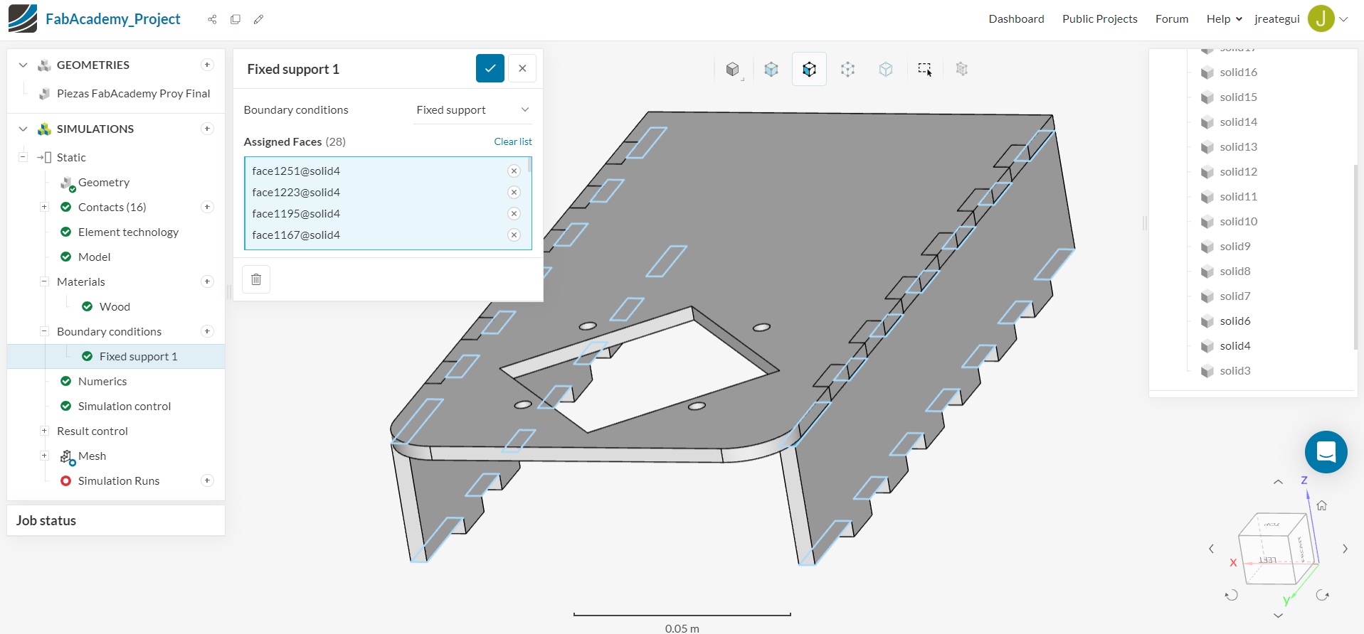
Once the selection was completed, the Fixed support window shows the geometry linked with the fixed support feature.
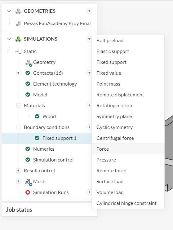
This is the moment to add the Force feature in Boundary Conditions
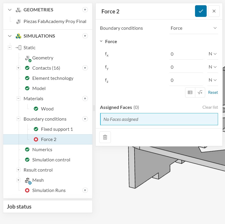
I defined the faces YZ to recieve the Z vector force
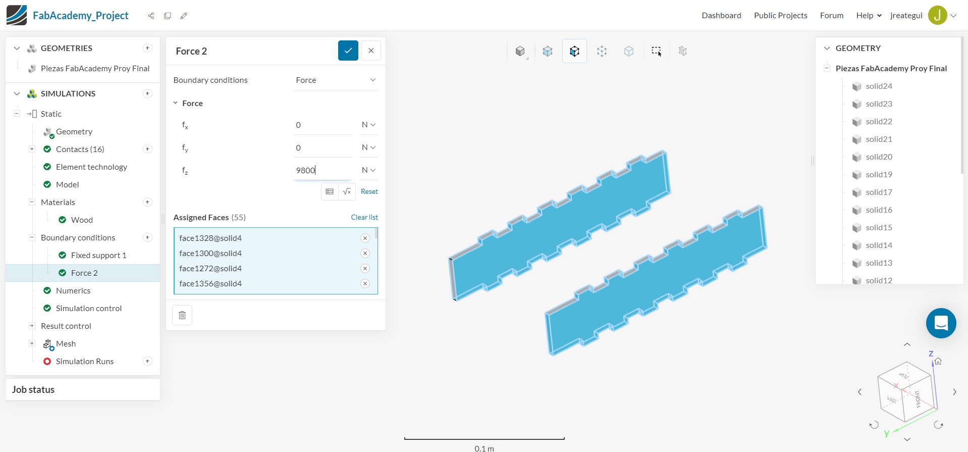
The interface shows in blue color the geometry used to recieve the force and in the force window dialog
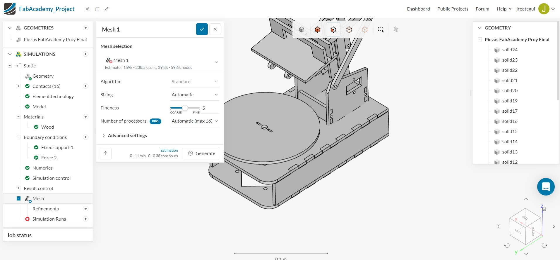
Now is time to make the mesh analysis, it's a crucial step because SimScale uses Finite Element Analysis to calculate the object behaviour, in this way FEA needs a mesh
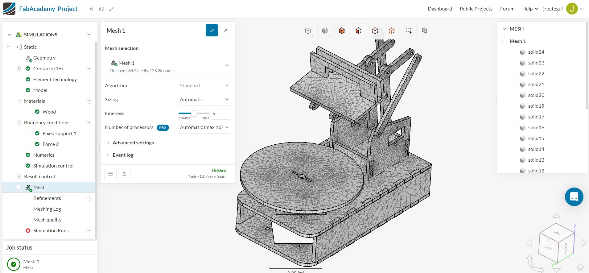
After the mesh process we can observe the nodes are more closer to curve edges, it's beacuse the mesh algorithm needs more triangles in the curve to define the shape
Conclusions: There are several CAD systems that can help to produce design. For me Rhinoceros 3D has a interesting tools to combine 2D and 3D design, it means less time to design, document, and fabricate. Before the fabrication process is necessary a virtual test in physics simulation, I choose SimScale, a web service to analyze 3D models with fluids, heat analysis, and static analysis, and has got a native integration wirh Rhinoceros 3D