Week 3:
Computer-controlled cutting: Design, laser-cut, and document a parametric press-fit construction kit,
group assignment:
Characterize your lasercutter's focus, power, speed, rate, kerf, joint clearance and types
individual assignment:
cut something on the vinylcutter: design, lasercut, and document a parametric construction kit, accounting for the lasercutter kerf, which can be assembled in multiple ways, and for extra credit include elements that aren't flat
This link shows the group Assignment task: Group Assignment Information
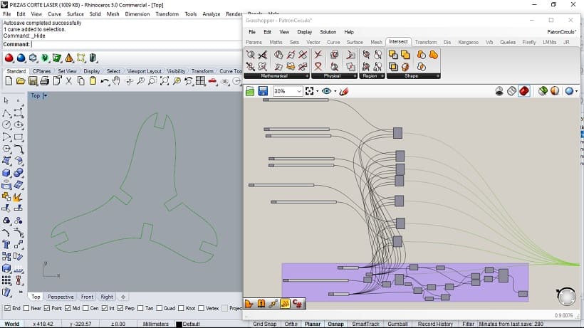
Design the pieces in Grasshopper Parametric System.
Parametric Modeling processes
1. Design the shape.
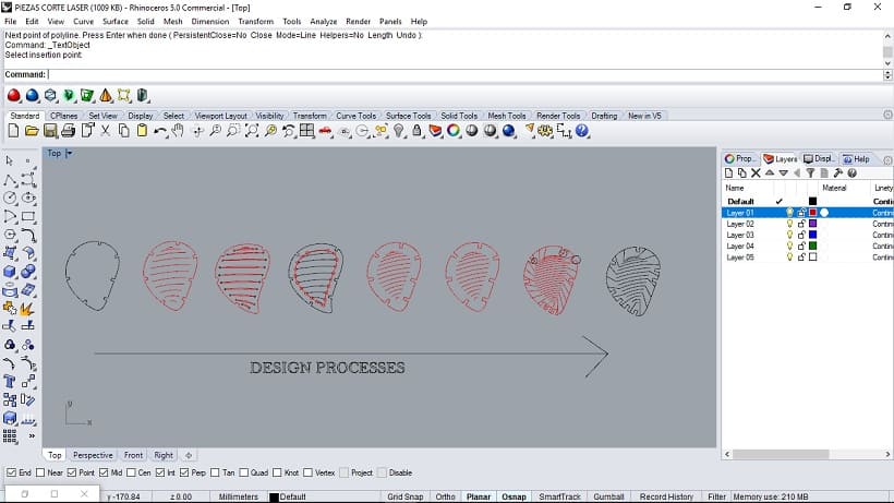
The design goal is related to reach the correct parameters combination between the material performance with lasser cutting process and the design flexibility pattern, in this way the process works with a form made in Rhinoceros3D and a parametric workflow with Grasshopper 3D.
2. Design the join.
To define the join deep We need to considerer the material thickness
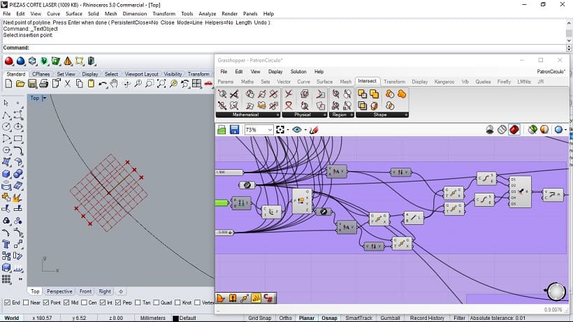
The join was a crucial feature because I made a lot of test before to take a final choose. In this way I made a parametric definition that analyzed the curve and define perpendicular axes, and Offsets tu predefined a hole
I used the knowledge from group assignment related with plywood, in this way I worked with a carf with 0.8 mm of size in the begining of process and plywood with 1.5 mm of thickness.
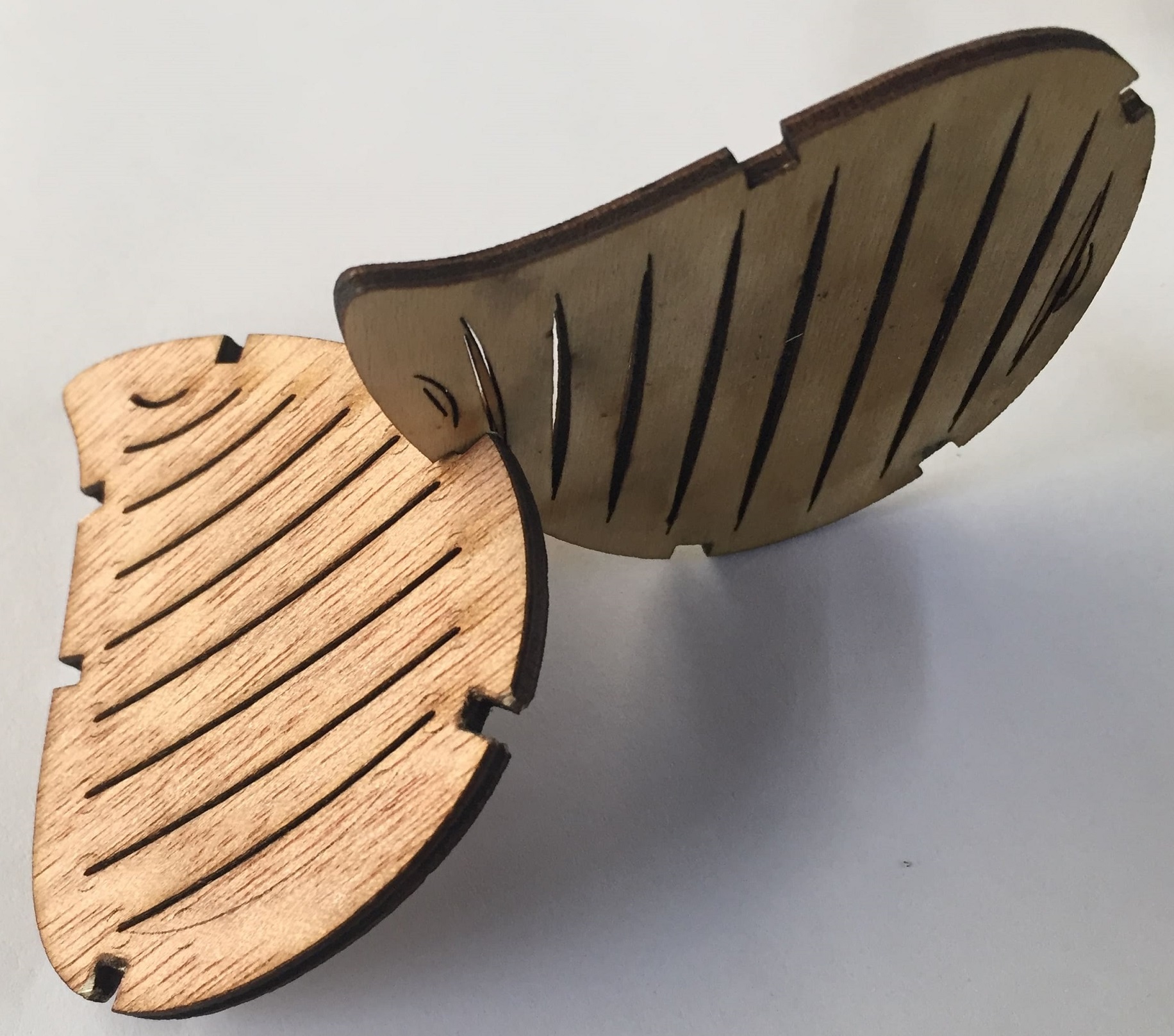
3. Design the flexibility pattern.
To define where will there the joints, I connected the inside circle subdivision points with the outside circle subdivision points in order to made lines that allow me fold the object. The first curve and the second curve (the inner curve) have the same points subdivision, to Connect them
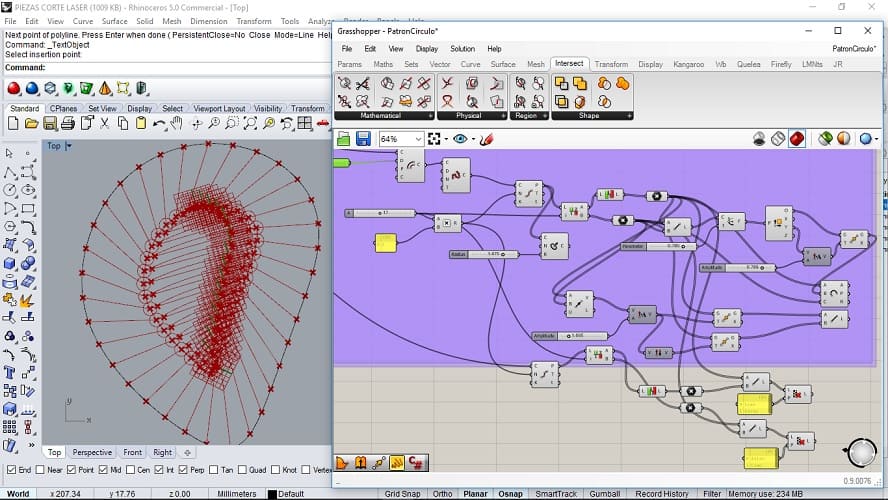
To transfer the results of parametric process I had to use the "bake" command, in this case I made several objects with different parameters values
4. Design to export.
To fabricate this design we need to export in .dxf format in Rhino
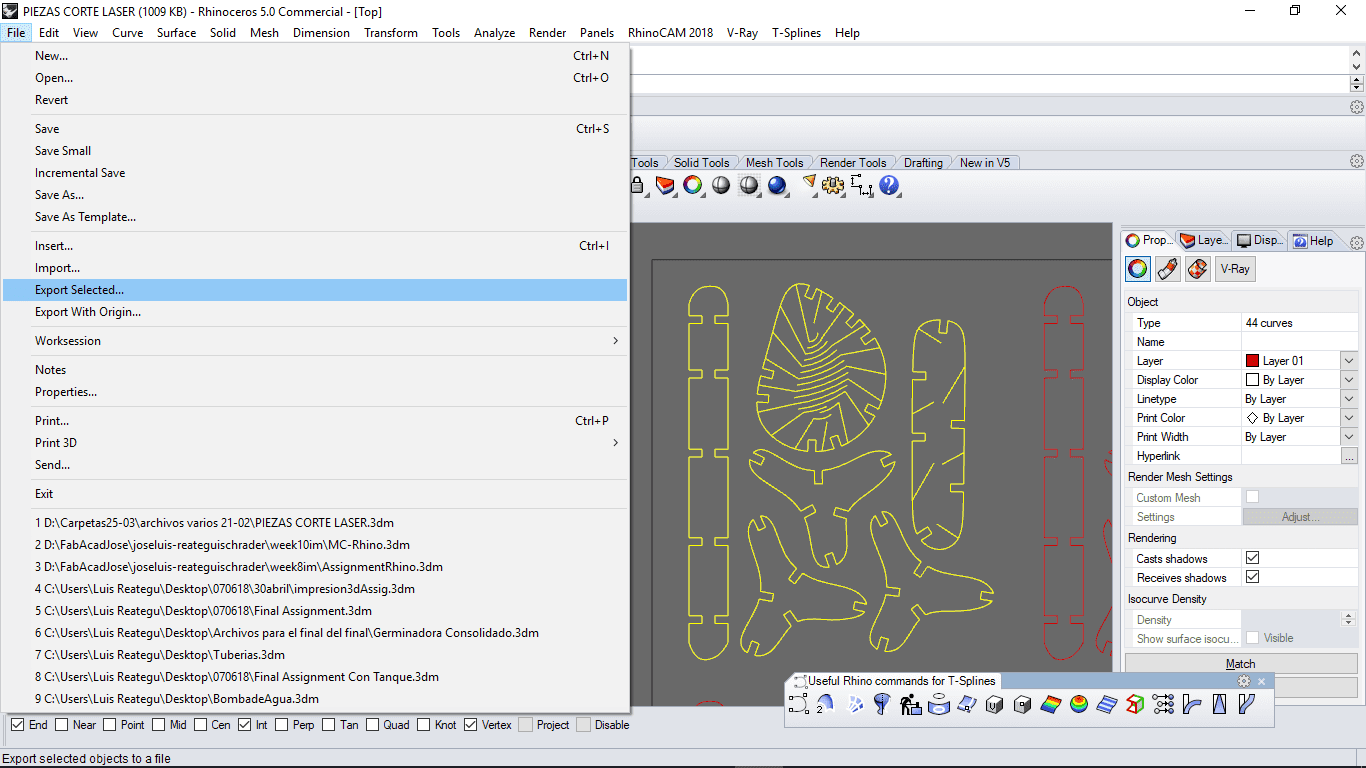
The first step is select the objetcs that we want to make, after that we have to go to file and Export Selected option
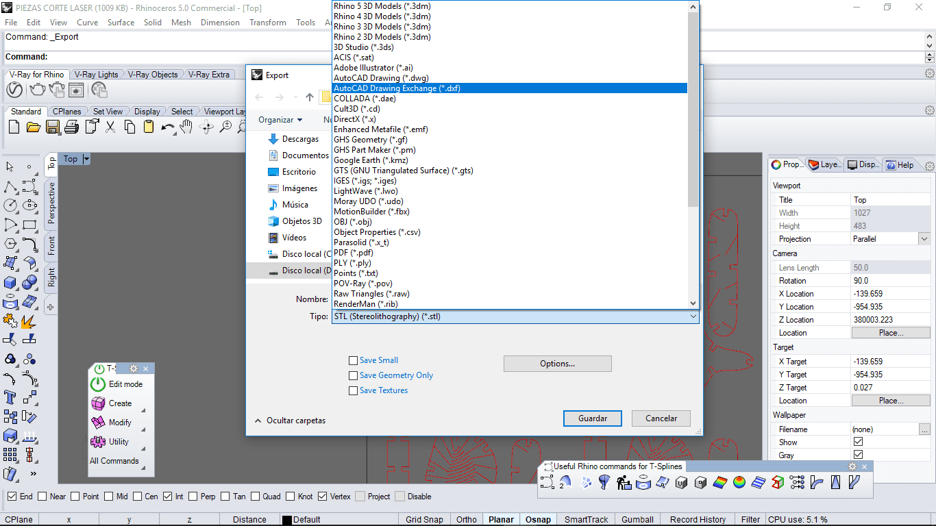
I choose Autocad Format file, in this case "dxf" file type, because I had more good results, compared with another formats
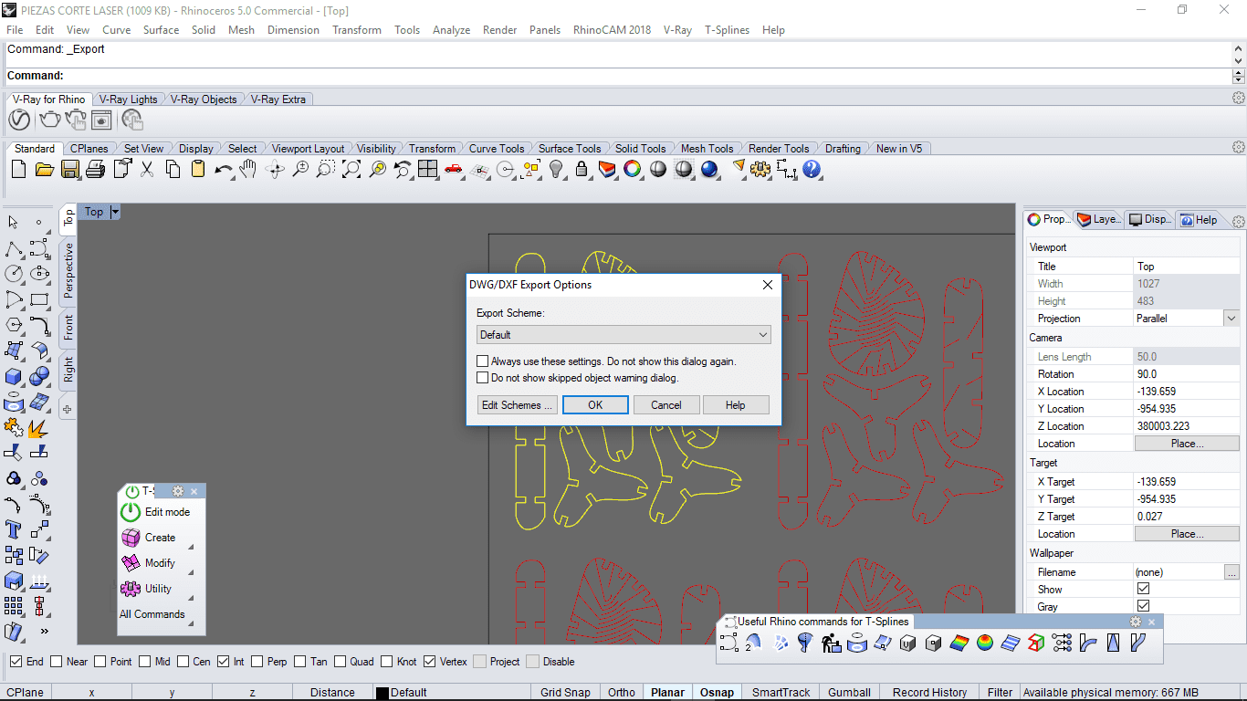
I export with defect setting options, it means only push in "OK" button
5. Import dxf file to CorelDraw.
I used Corel Draw to configure the file features and Laser properties
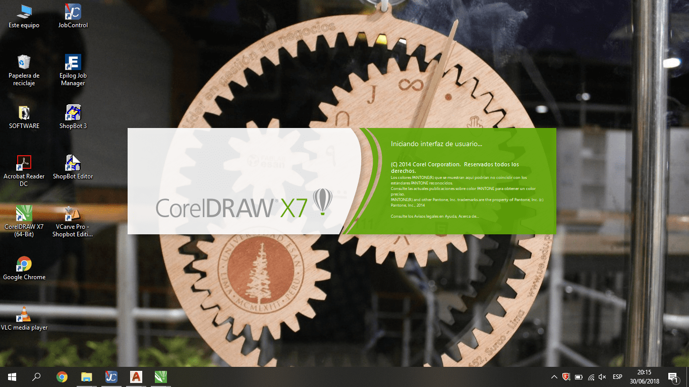
This software requieres a license to work, the Fab Academy node has one, but If there is another option like RDWorks, is better
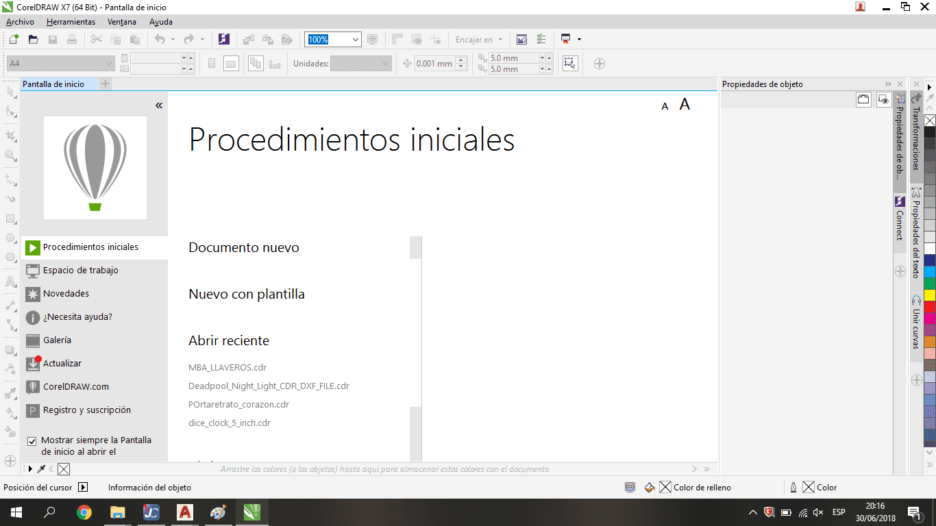
Like another vector software for design we have a canvas and tools to design or edit the shapes
6. Setting the CorelDraw features.
After open corel draw, choose File-->New. After that specify the board measures
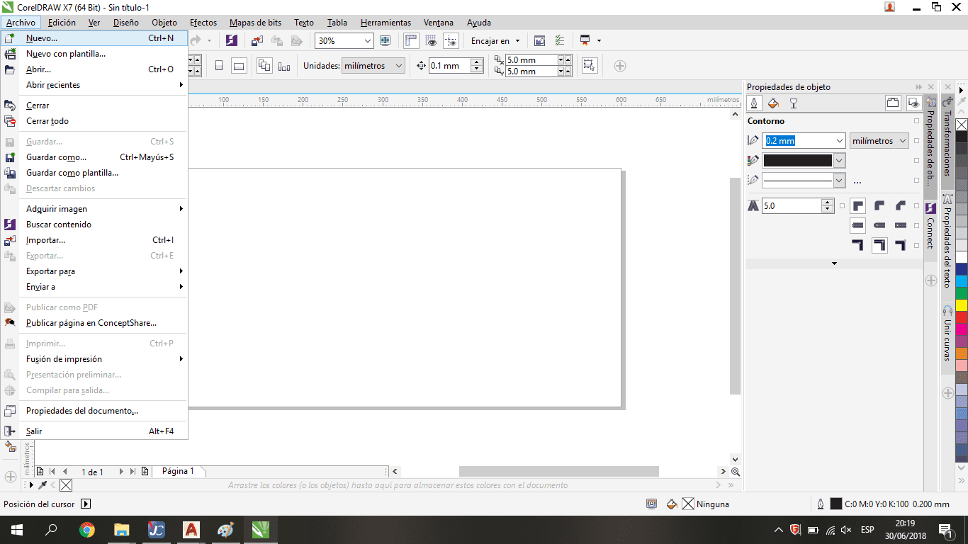
After "new" command we have to define the board measures
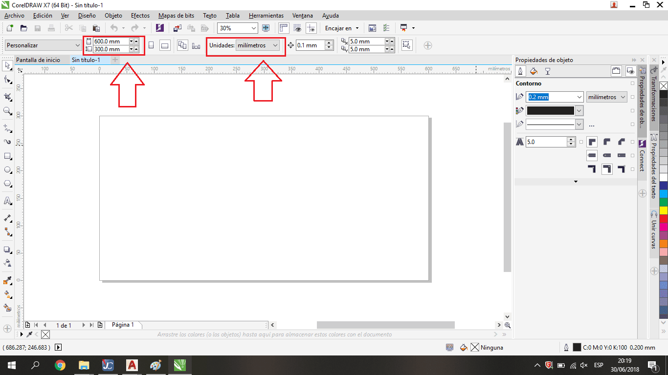
This step is very important because the laser machine needs to work with the same measures, it means the physical height and width have to be the same with the digital workspace or canvas into Corel Draw
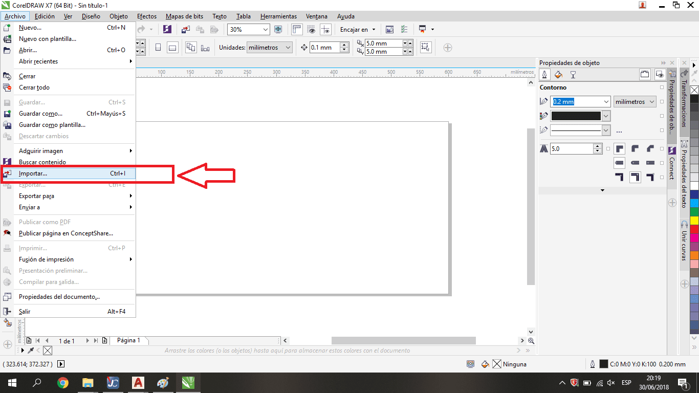
Choose the import option
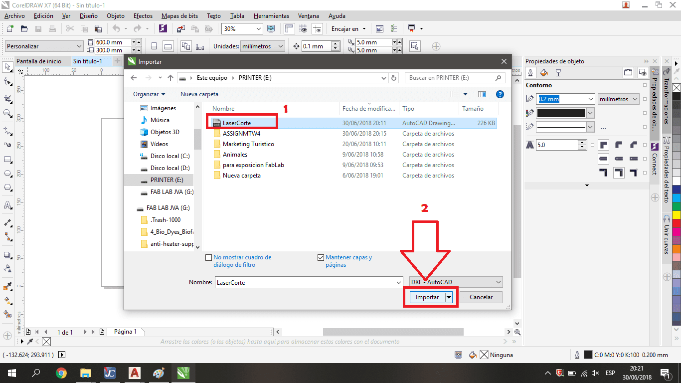
We have to choose the dxf file made previously, it's important define the format, in this case "DXF-AutoCAD"
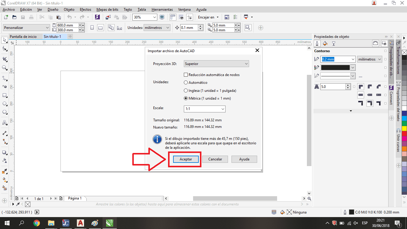
I used the defect configuration in the dialogue box
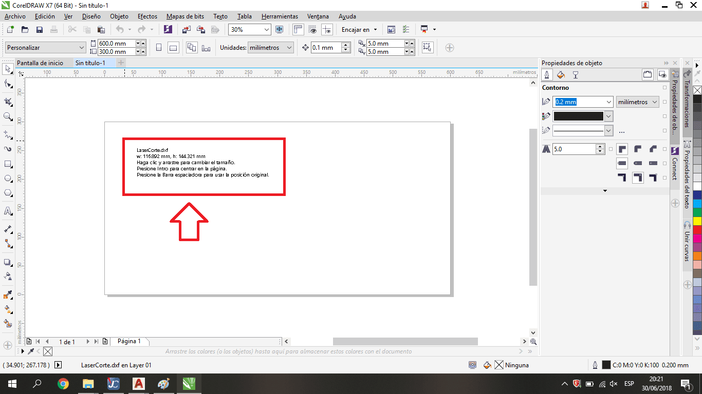
with the mouse we can drag into the canvas to put on our dxf information
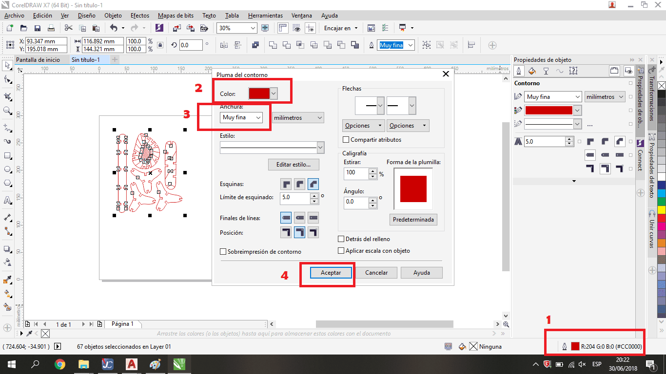
7. Define the layers features.
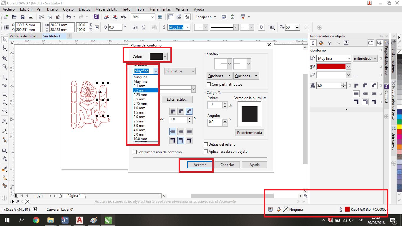
Define the characteristics to cut or to record. To Cut uses the color red, and in the width: "very thin line". To record the color Black, and it is necessary to say what is the thickness of the line to be recorded
Is usual that we have two layers to work, the first one is the carv layer with low laser power, and the second is the cut layer with the highest laser power, is very important to know the material constraints because each material has different ways to respond the laser cutting process. In the group assignment I can see it, the wood board has different cutting parameters compared with acrylic board.
Now you have to go to the Print option, to configure the file that is displayed in the Trotec cutter program.
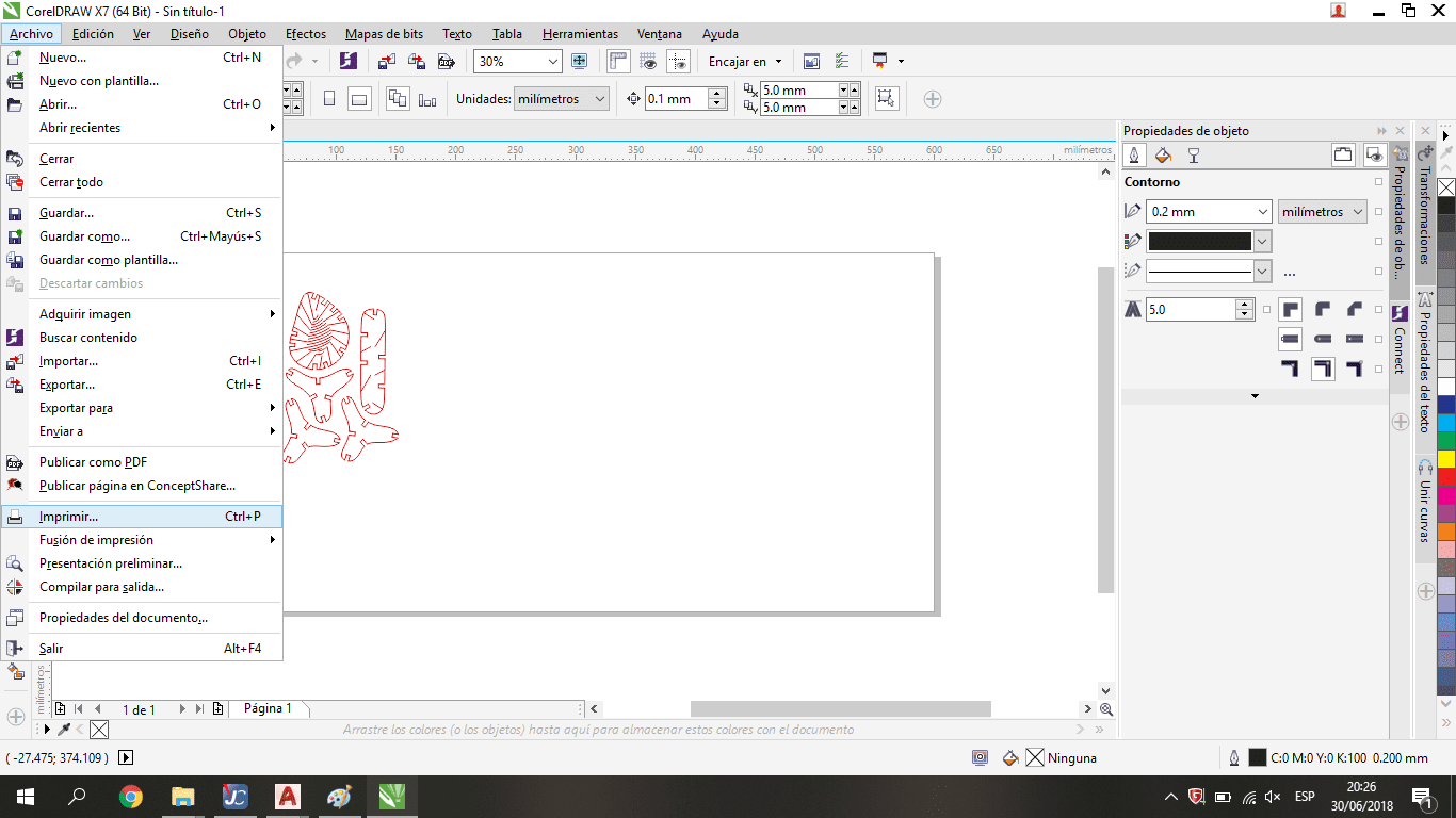
This software works as a virtual printer and allows connect Corel Draw with the laser cutting machine
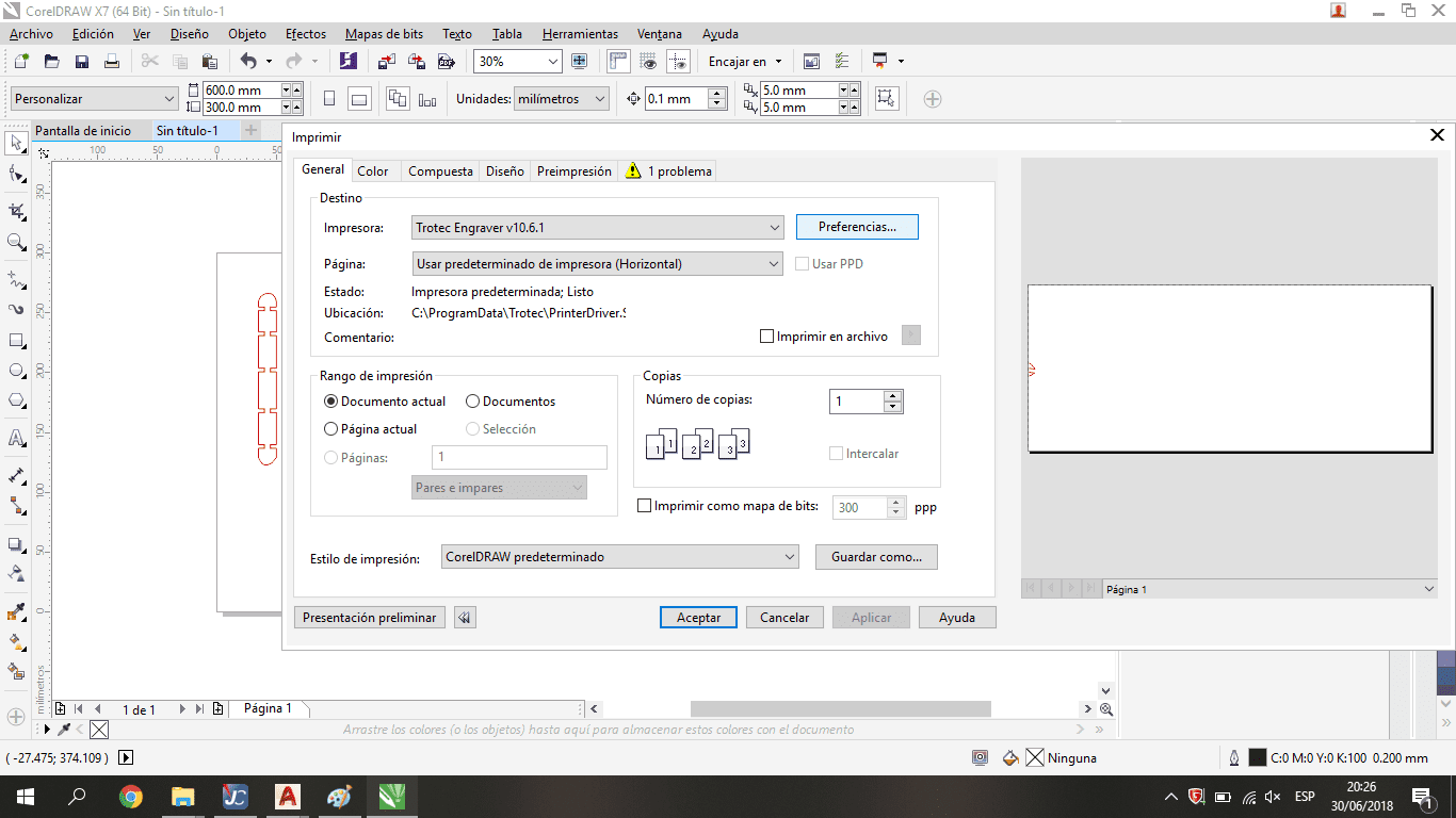
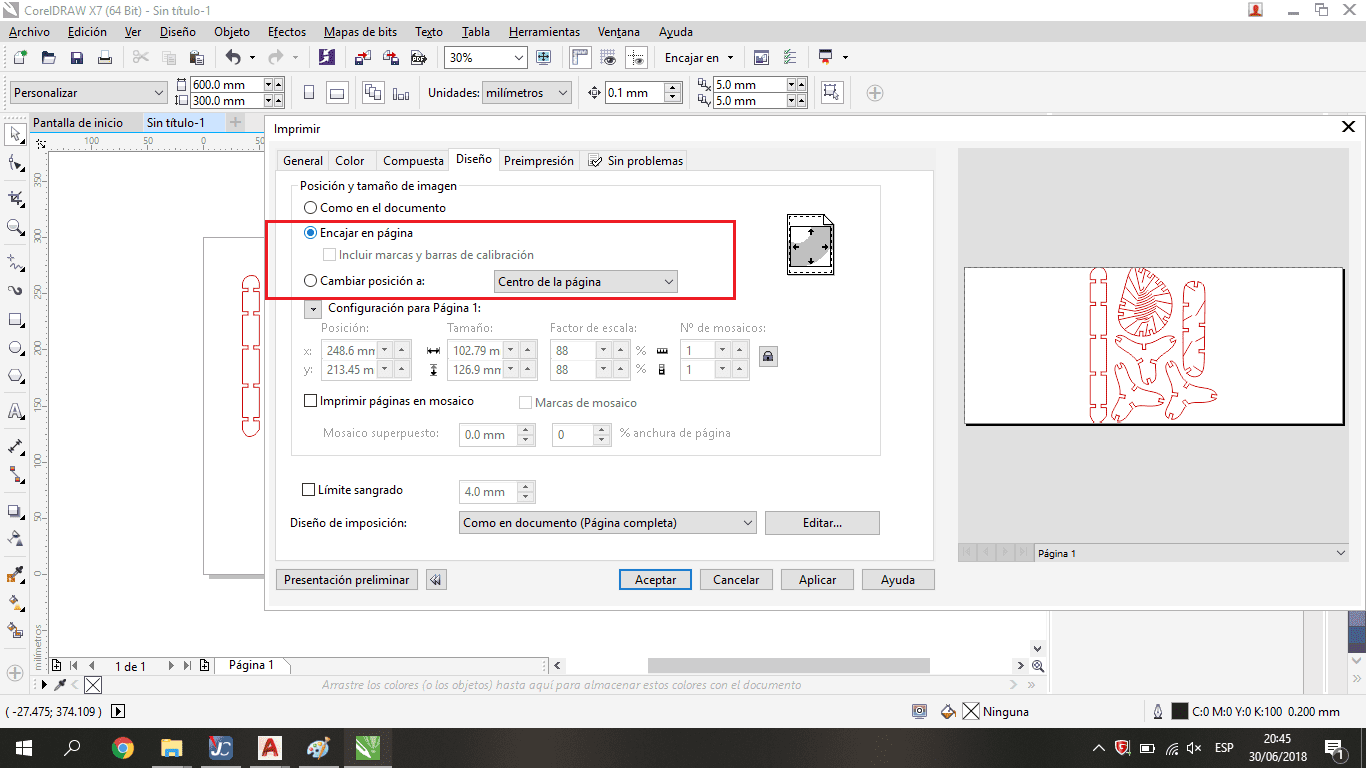
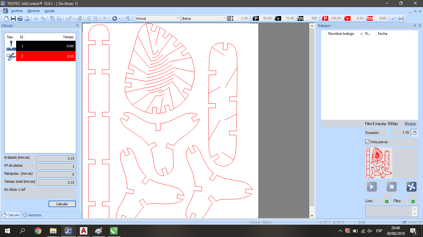
We have to match the machine constraints with the software constraints to avoid warms flags. The right window shows the geometry that the laser cutting machine takes to move.
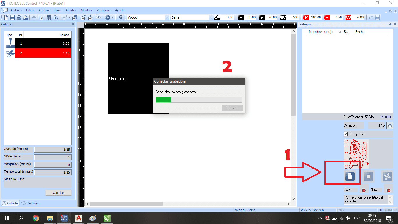
Once We are in Trotec Software We need to include the the file from rigth side to left side. Click on Calculate Button option. Click on Connect Button and wait for the machine connection
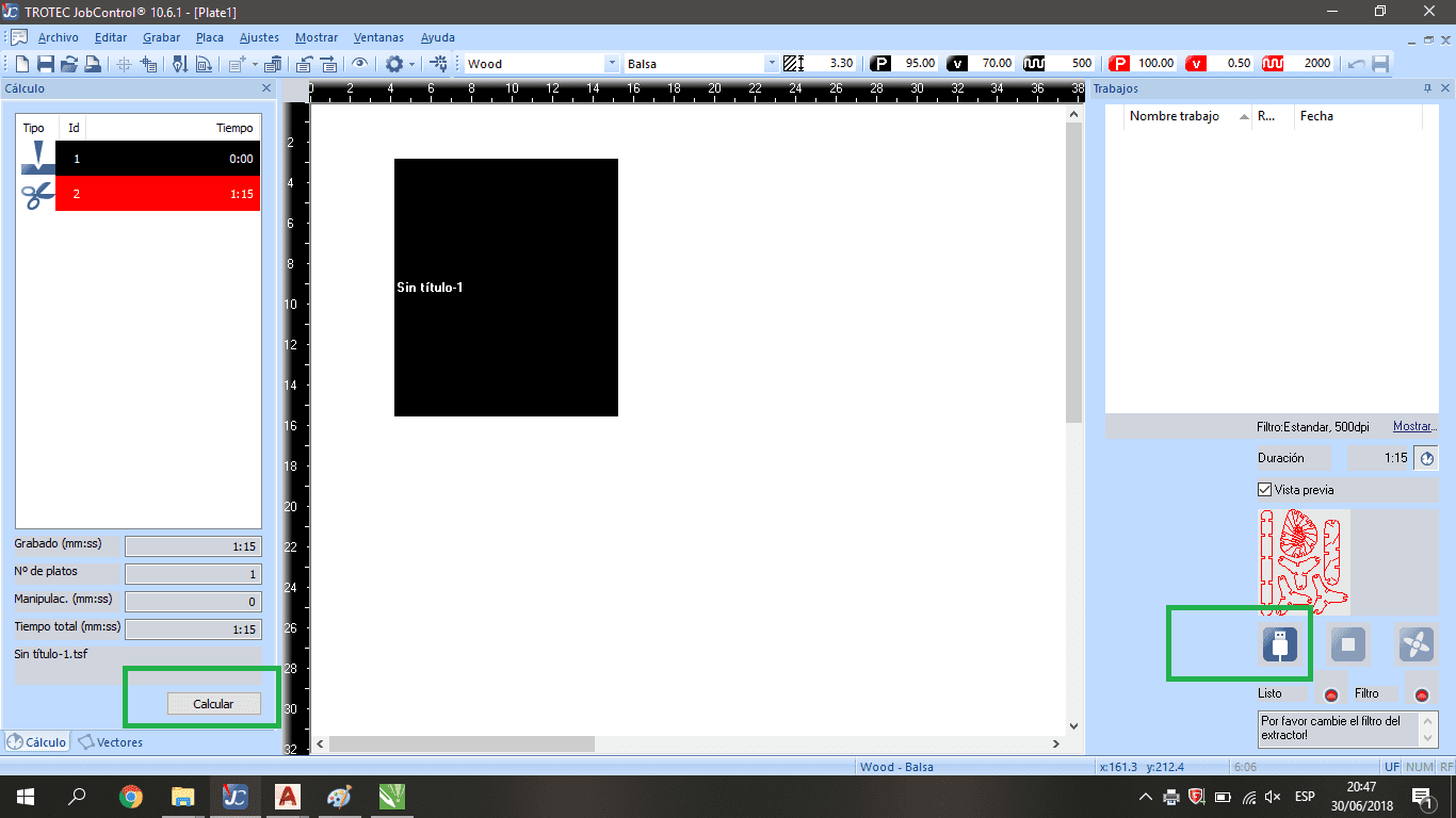
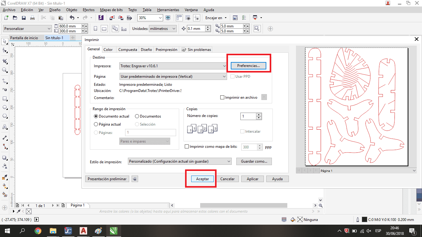
We have to push the "Calcular" button to know how many minutes needs the process, in this way know that the laser cutting machine takes correctly the information from Corel Draw.
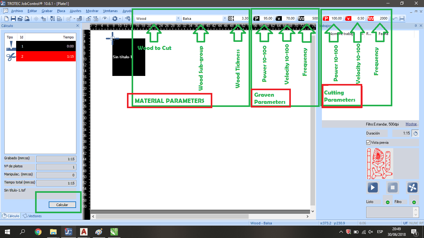
We have to consider the parameters to process information: First one, the material parameters: In some cases the material parameters was register previously, in my case I used wood because I worked with plywood. The second parameters group is related with graven parameters like power, velocity, and frequency. And the last one is related with cutting parameters. The key difference beetwen graven and cutting parameters is the laser intensity that is related with the power, this number define the energy that the laser use, the velocity, with lower speed the laser has more time to cut the material, and with frecuency whit high values the laser can cut more material.
When I finished the setup configuration I send the geometry information with button ">"
After that I could see the machine works and the instructor said me the safety requirements, like the distance from the laser machine, the safety lens, and the emergency button that I have to push on if I realize the machine doesn't work very well.
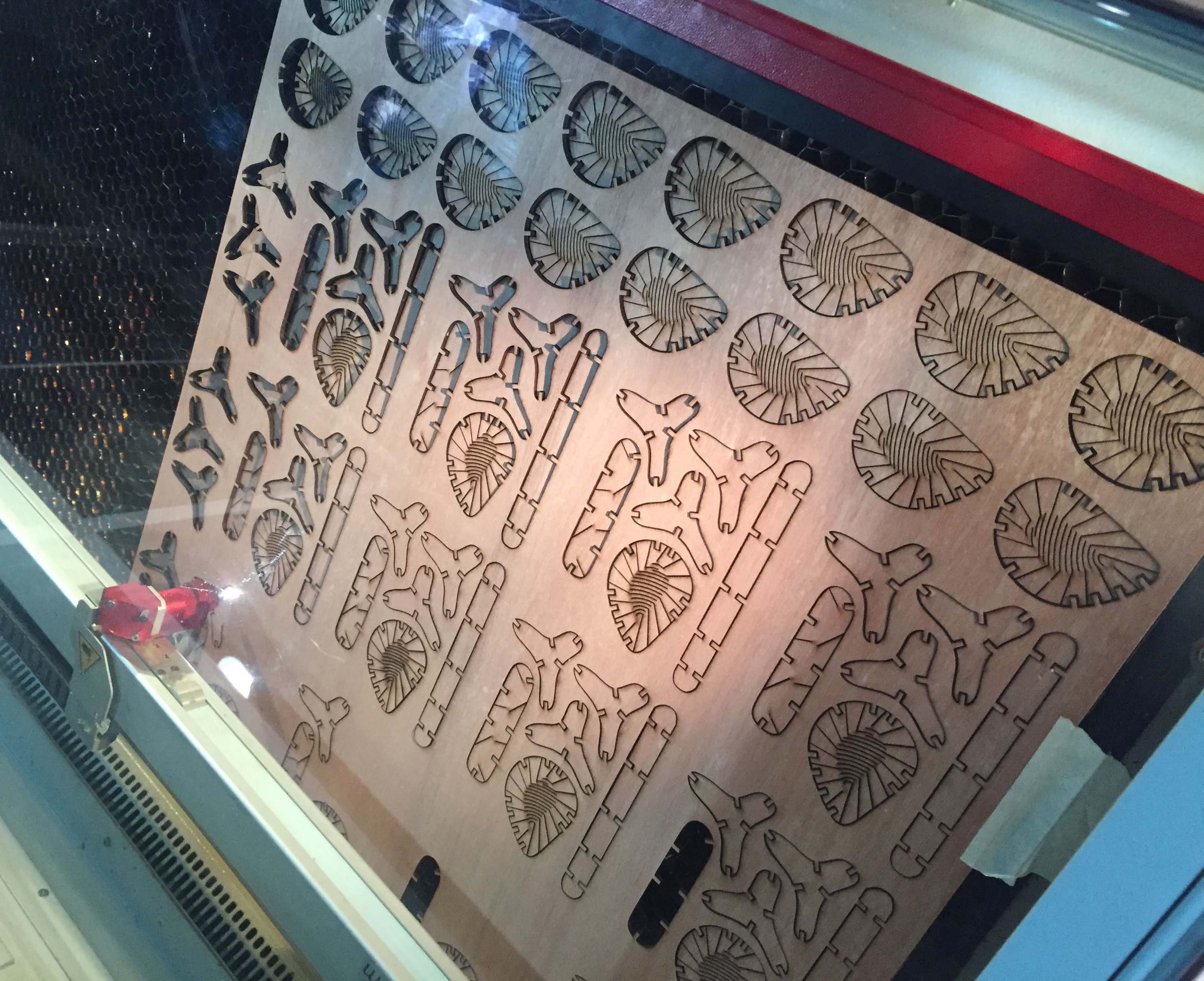
I've used this following features to cut the MDF board
I worked with several join measures, to test the pressure and the press fit engage
We need to test the material-cut tolerance, it means how much differences there are between the digital design and the laser machine results.
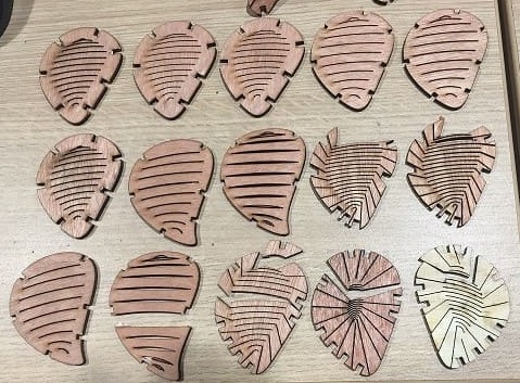
The Join test wants to know the material flexibility, this test show the fail in the design and the anchor limits. the limits is 1.5 mm between a cut with other.
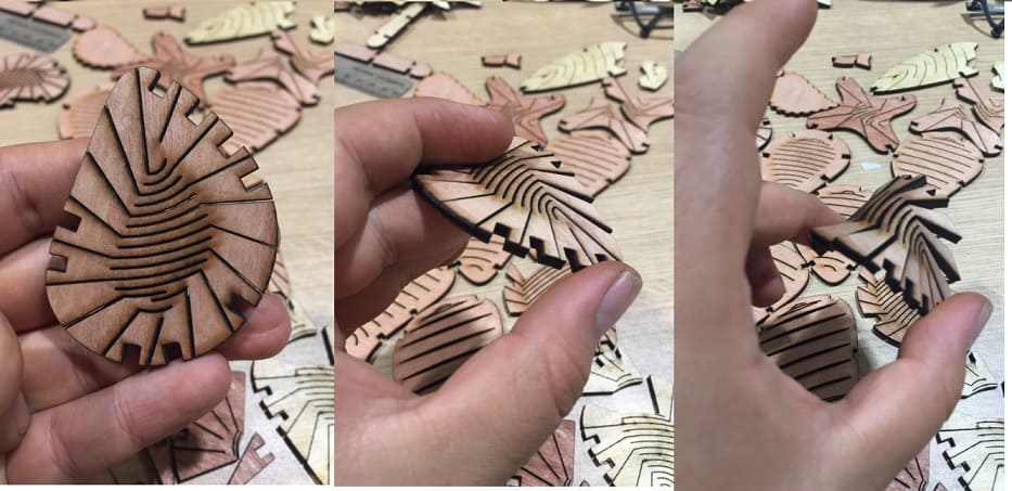
I test the cutting pattern to know the material limits
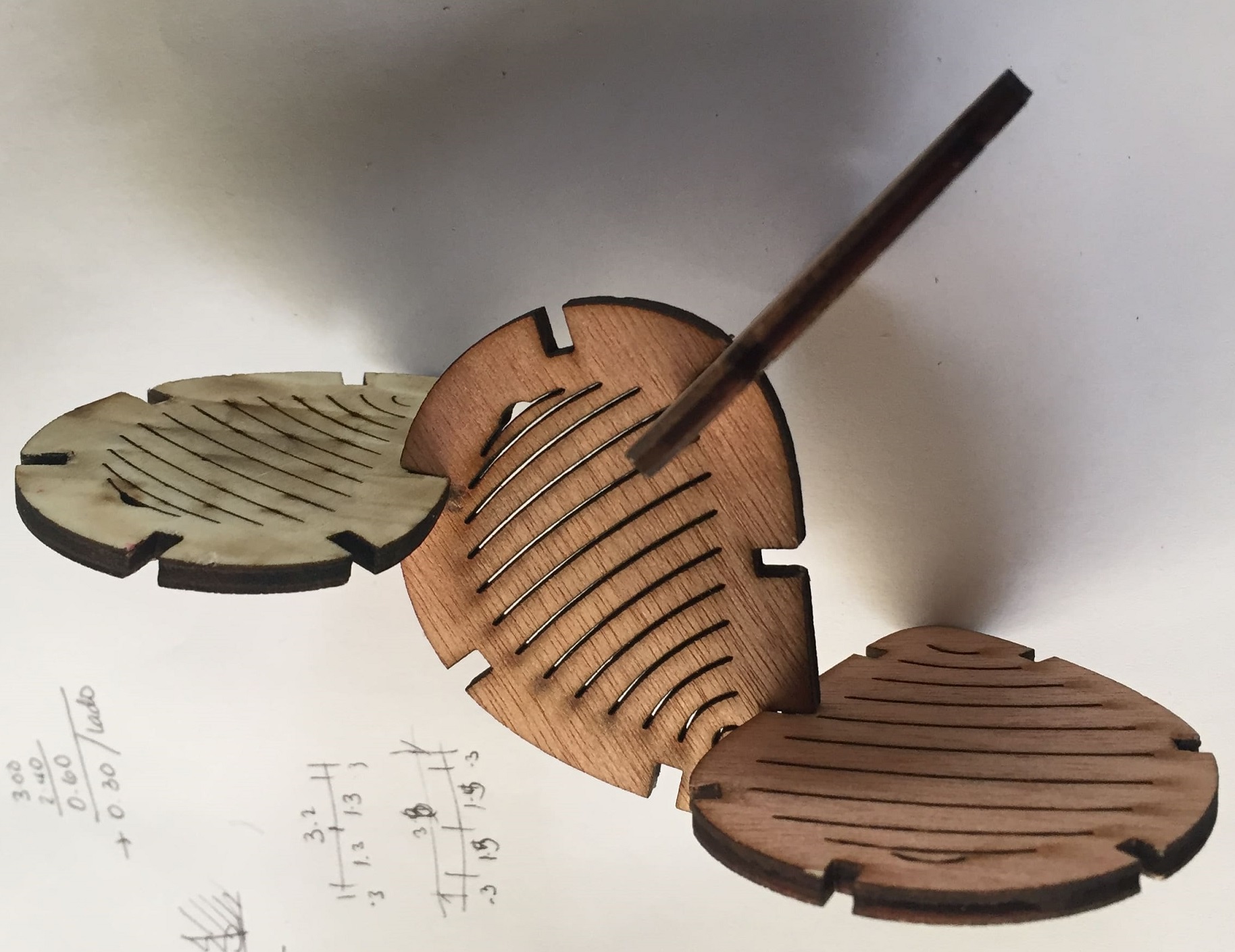
2. Explore the Multi-Directional Flexibility piece
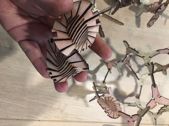
Design the second piece.
The second piece was made with 3 different curves because the angles in the curves avoid transfer the parametric definition

Like the first piece, this second piece has the same design and digital fabrication process
Design with the press-fit kit
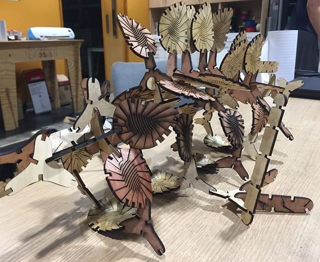
1.Development the form
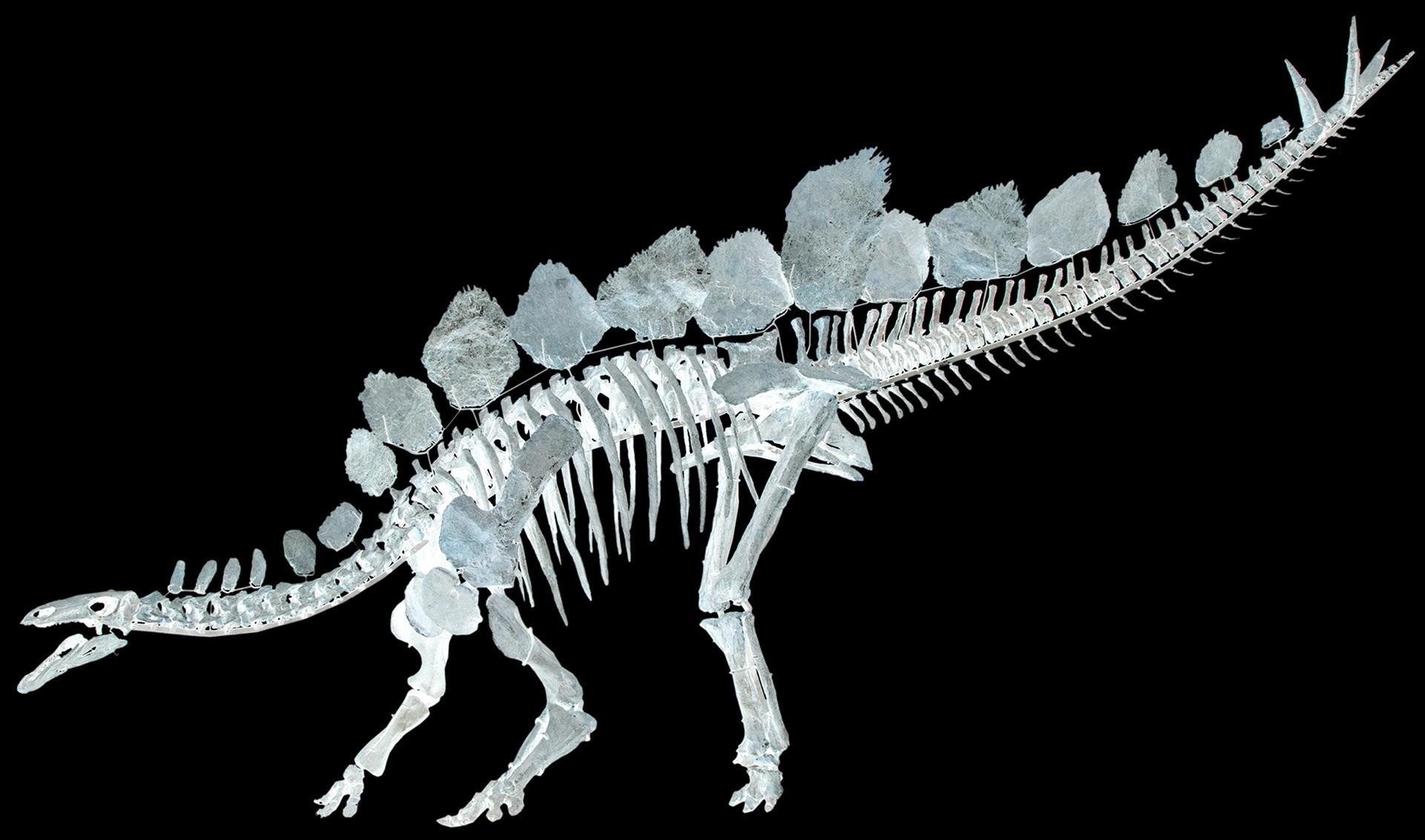
To made the press fit kit I got inspiration ideas from Stegosaurus
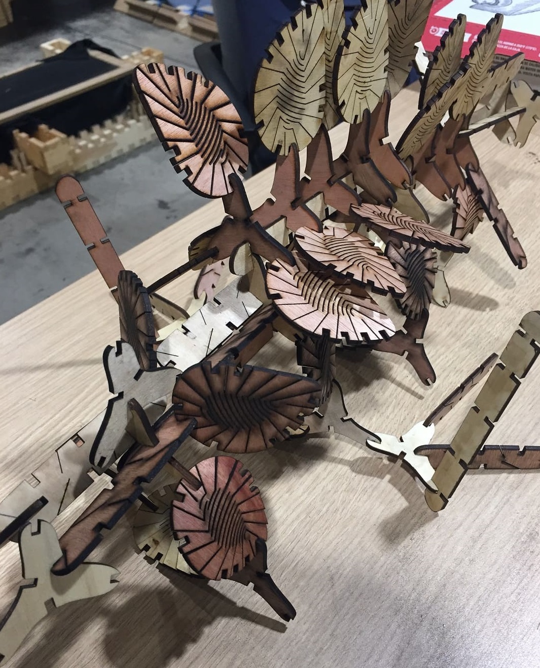
The second piece works as a dinosaur spine that organize the exterior bones
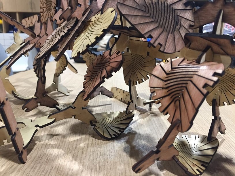
The kit has flexibity to looking for more different ways to assembled
Cut something on the vinyl-cutter-design
Design the pieces in Rhinoceros and export in dxf format.
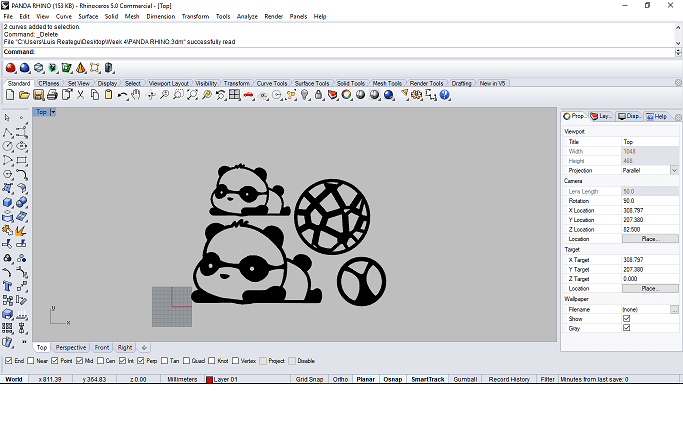
The first step, make the design with curves and hash command into Rhinoceros3D, the hash command needs closed curves to work.
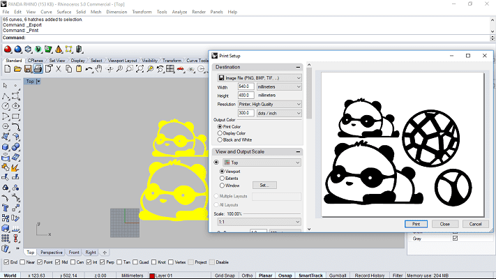
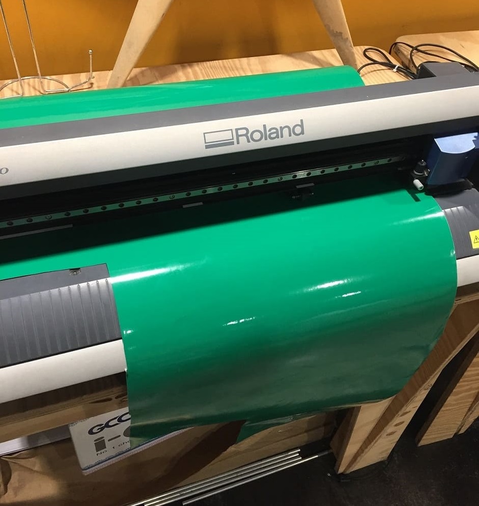
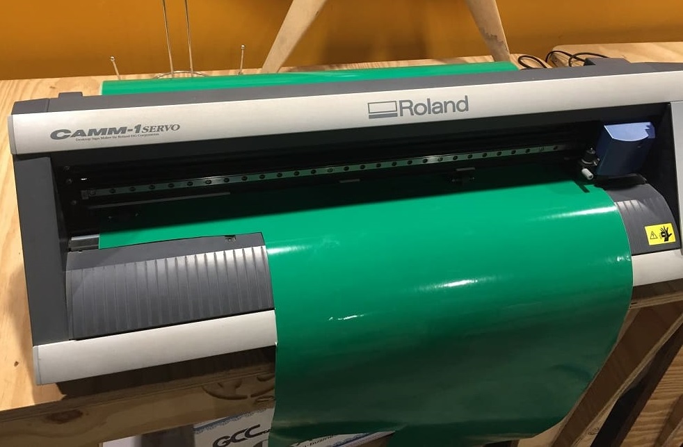
For the export process I used the print command because I wanted a picture, the Roland Vinyl Cutter needs this kind of file
We need to do the following steps to prepare the Roland Vinyl Cutter Design.
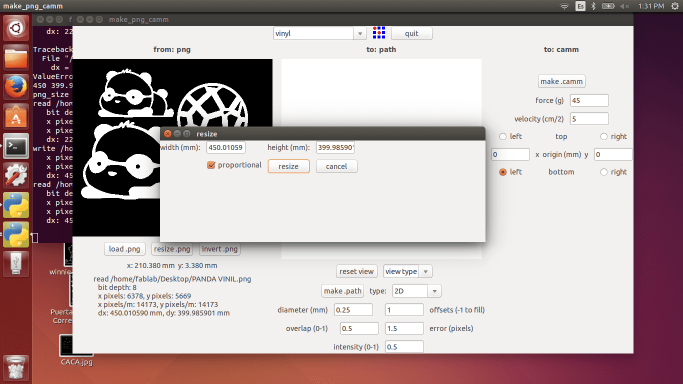
The correct size is very important, we have to consider the machine features, like the picture width and height
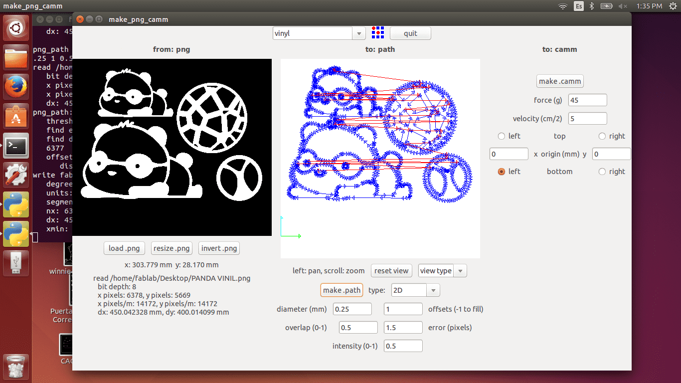
The first step before the cutting process is define the path
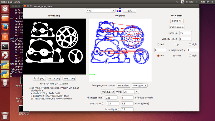
The second step is send the path information to Roland vinyl cutter
Prepare the Roland Vinyl Cutter, and then specify the cutting parameters. The machine needs to know the thickness and align vinyl to work
Send the path previously we created to machine with "sent it" option
once cut, the piece must be separated from the base with great care, and then stick it on a clean surface
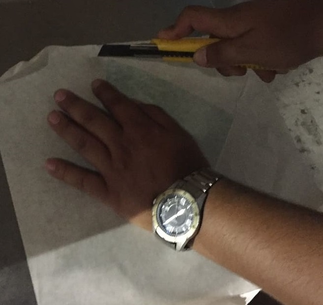
When the work finished we have to use a special piece of paper to extract the object, this piece of paper should have the same size that the object fabricated.
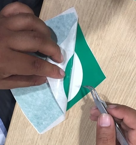
After that we have to use a tweezers for extract the design very slow
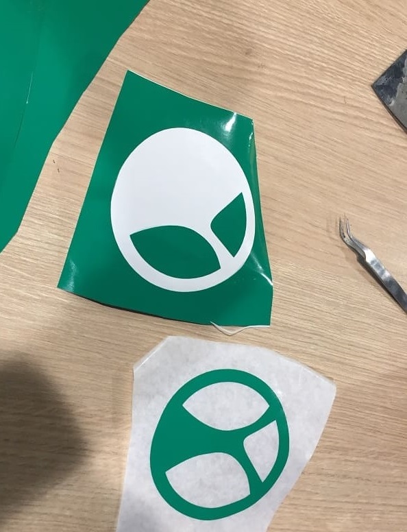
After extract object we have to paste into a clean surface
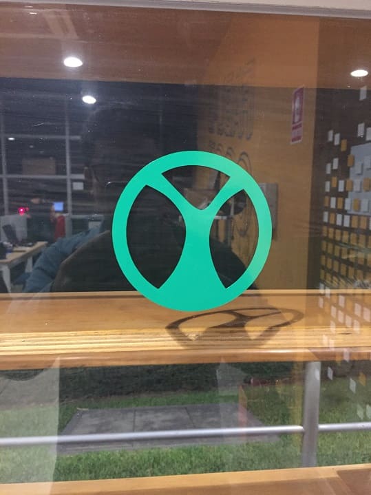
The last result is very intersting because the vinyl material is another way to fabricate digital design
I've used this following features to work with vinyl-cutter
Conclusions
The first step to consider is the digital fabrication process, my experience in this week shows me if we use laser cutting machine we have to export curves in dxf format, in another way if we have to work with vinyl cutter we have to use pictures. To work with laser cutting machine we have to know the materials features because each material responds in different ways.