Week 6
Electronics Design. Have you:
- Shown your process using words/images/screenshots
- Explained problems and how you fixed them, including how you worked with design rules for milling (DRC in EagleCad and KiCad)
- Included original design files (Eagle, KiCad, Inkscape, .cad - whatever)
group assignment development:
Individual assignment development:
The main Workflow to develop the board is the following
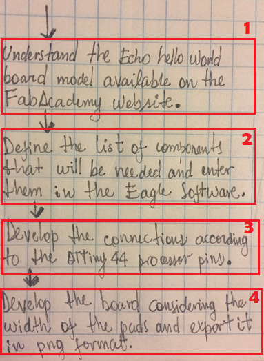
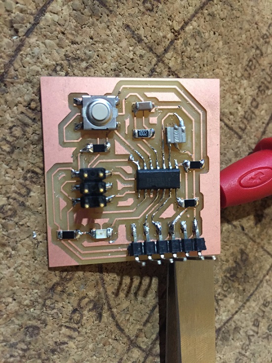
I used the Echo Hello World Board available in Fab Academy Page
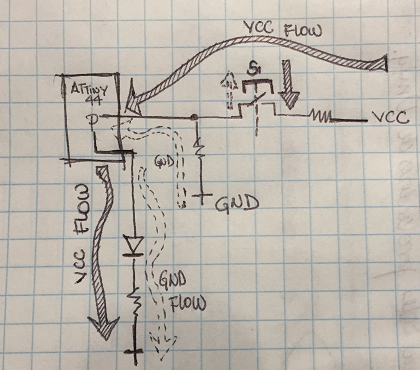
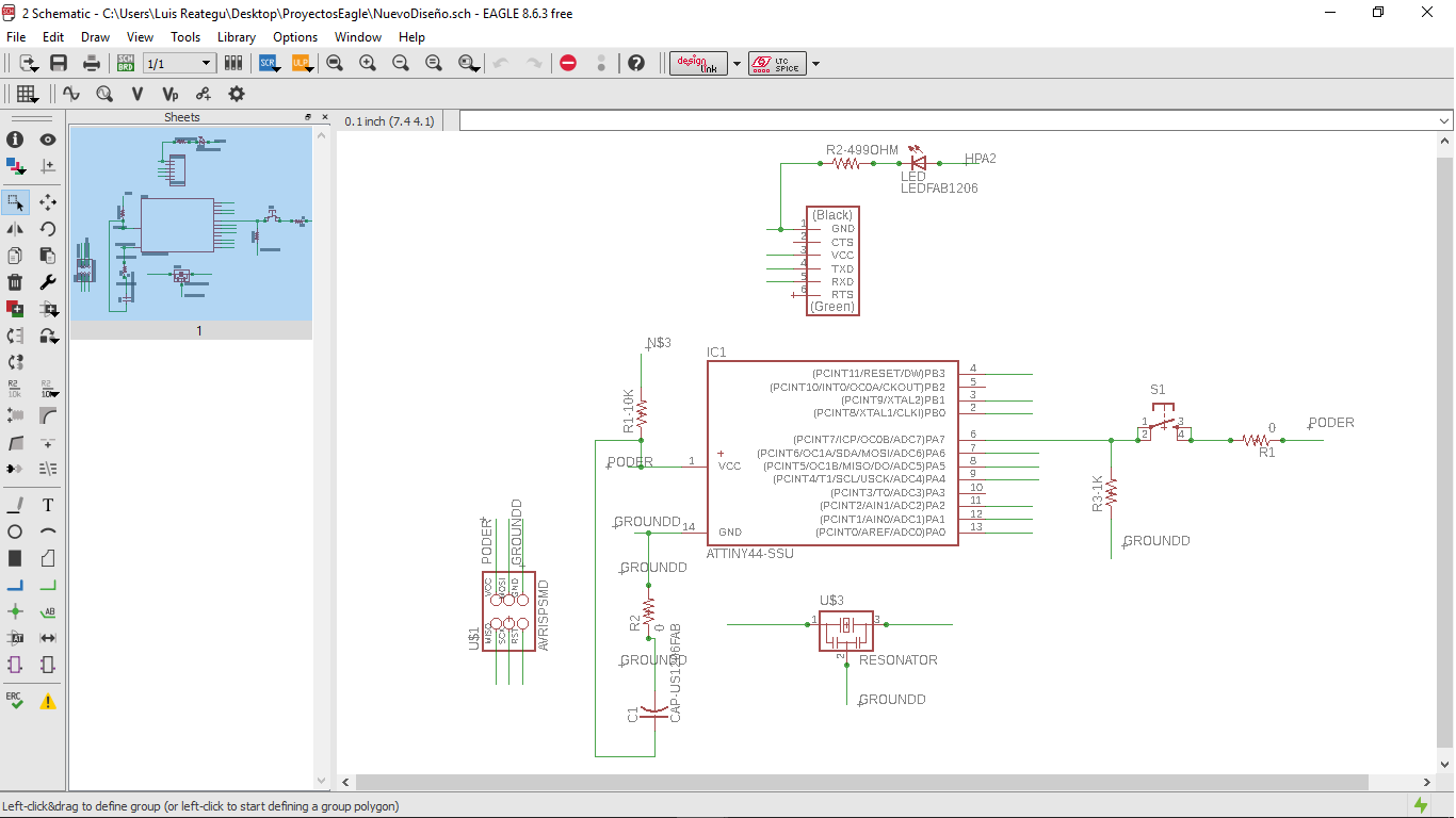
We need to design the PCB through Button functionality, I mean, when the Button is pressed, the vcc circuit are connect, but when it isn't connect, the GND is on, never the Attiny will stop having a connection. The signal interpreted to ATtiny is to transformed to produce the light on or lights off
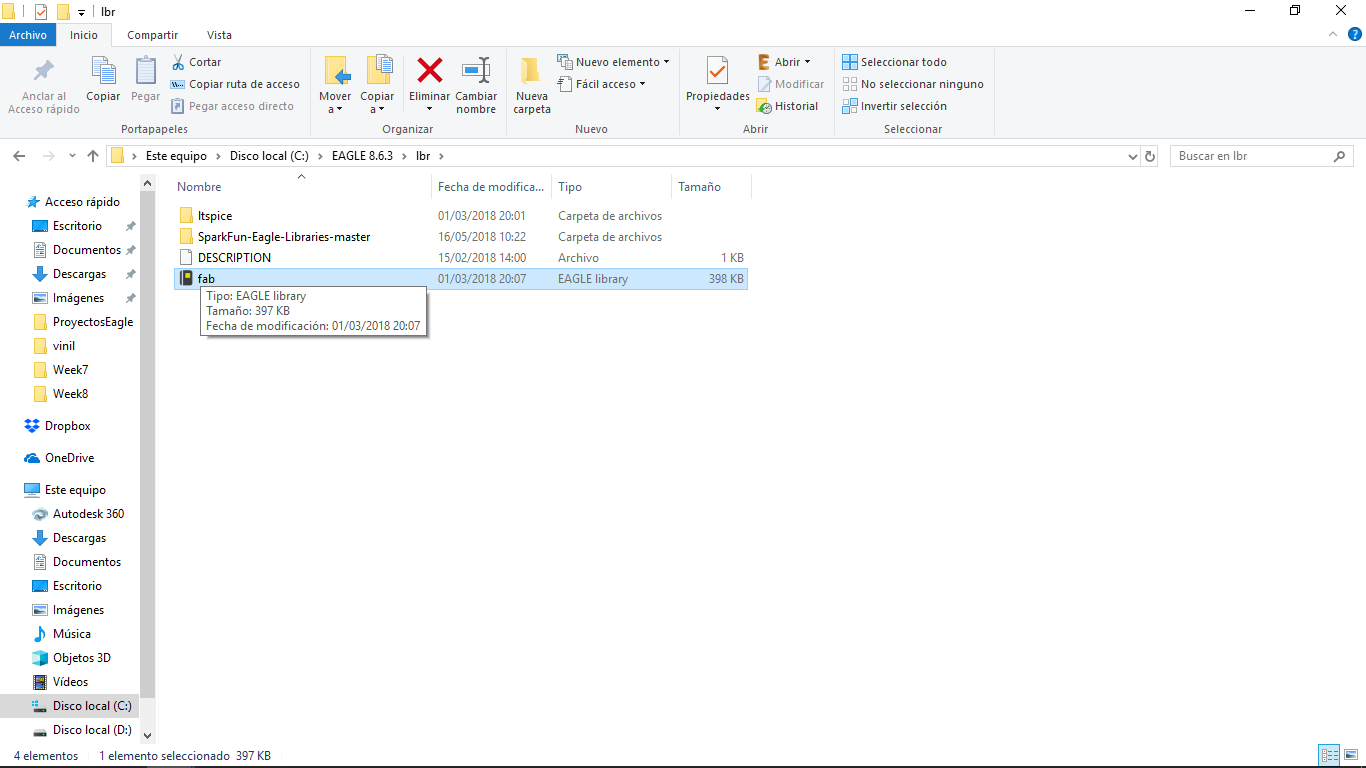
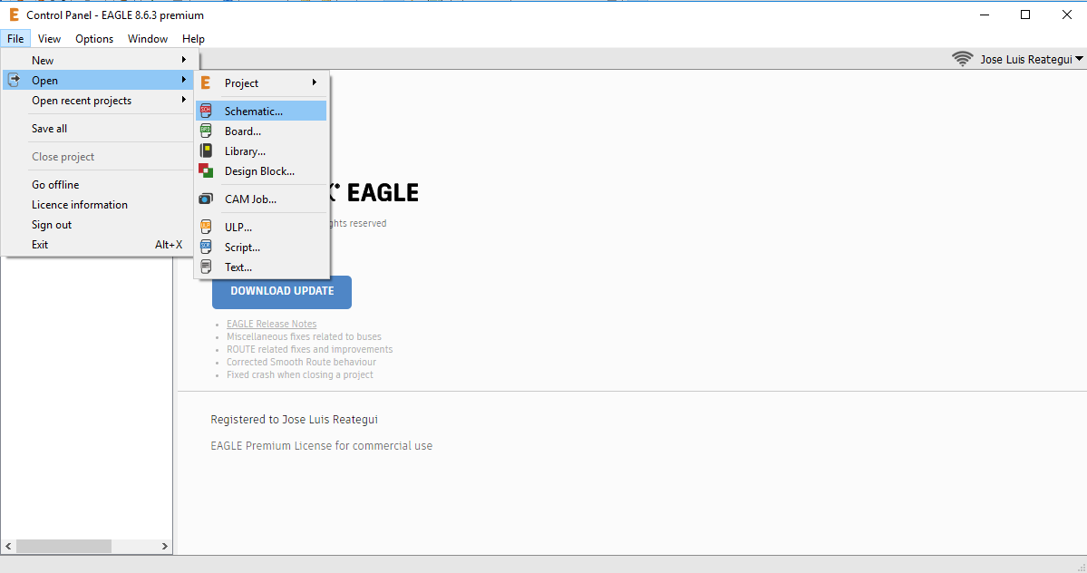
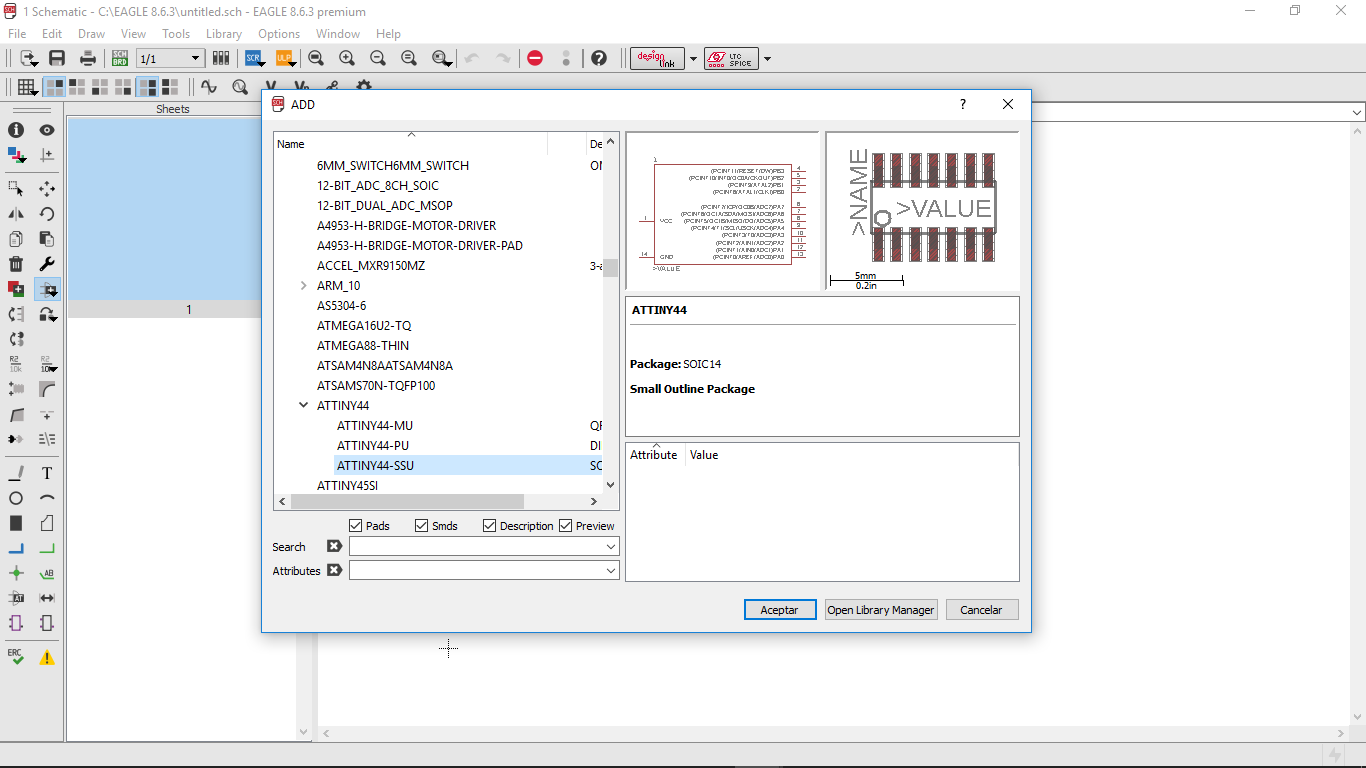
After choose the components I was import the virtual components from Fab Library in Eagle Software.
To connect the different components is very important to know how works the circuit. Understand this we go to, for instance:
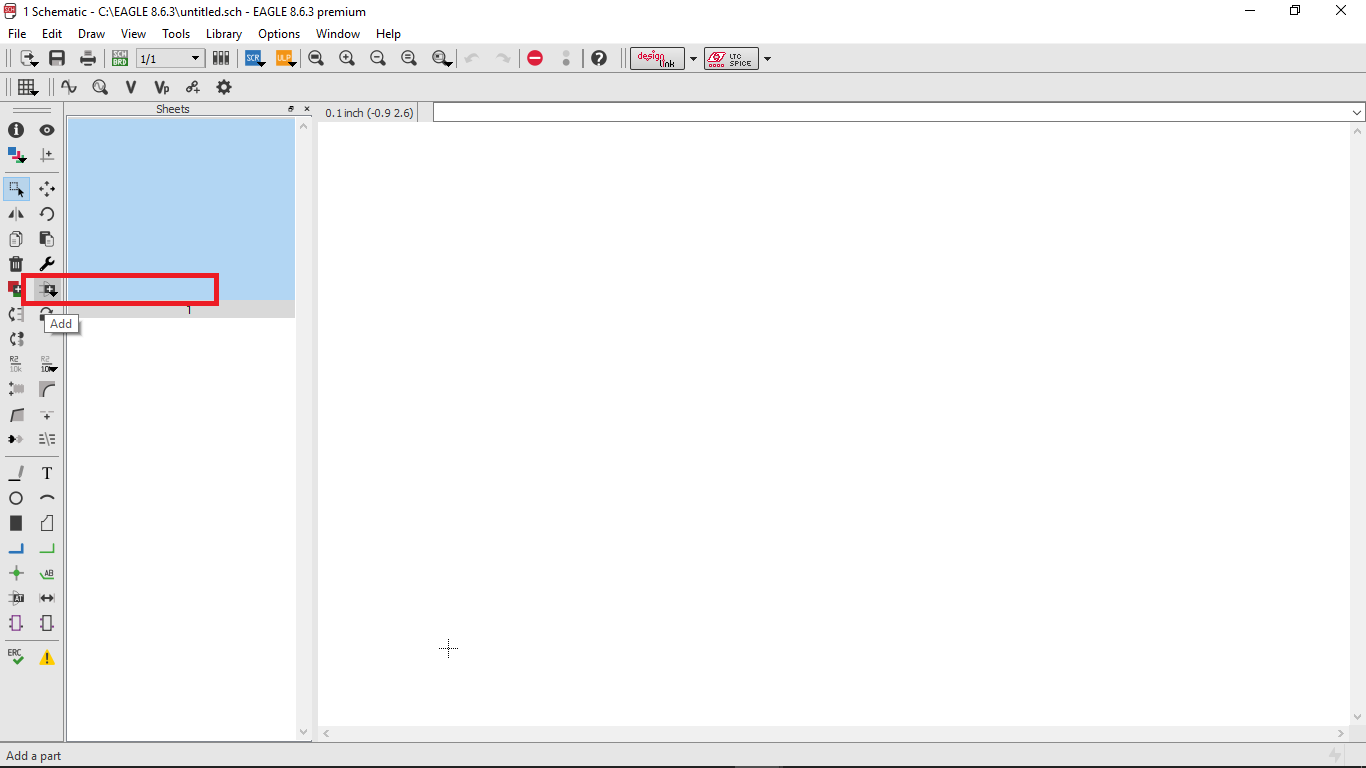
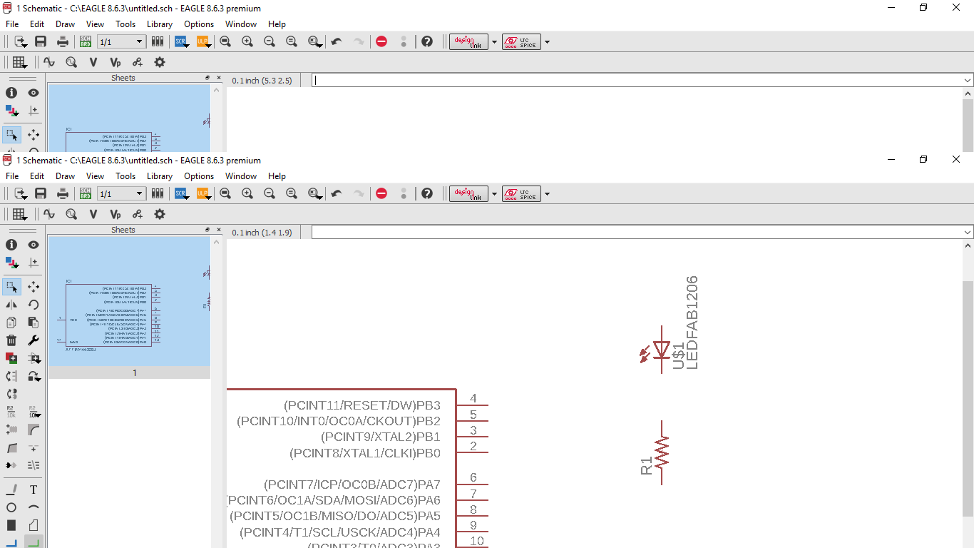
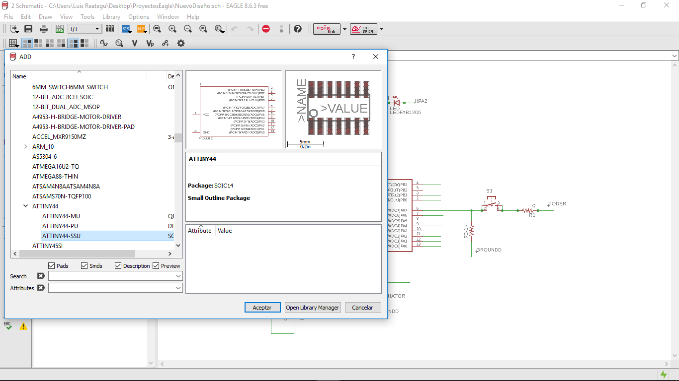
Demo How to connect components in Eagle
Demo How to connect components in Eagle from JOSE LUIS REATEGUI on Vimeo.
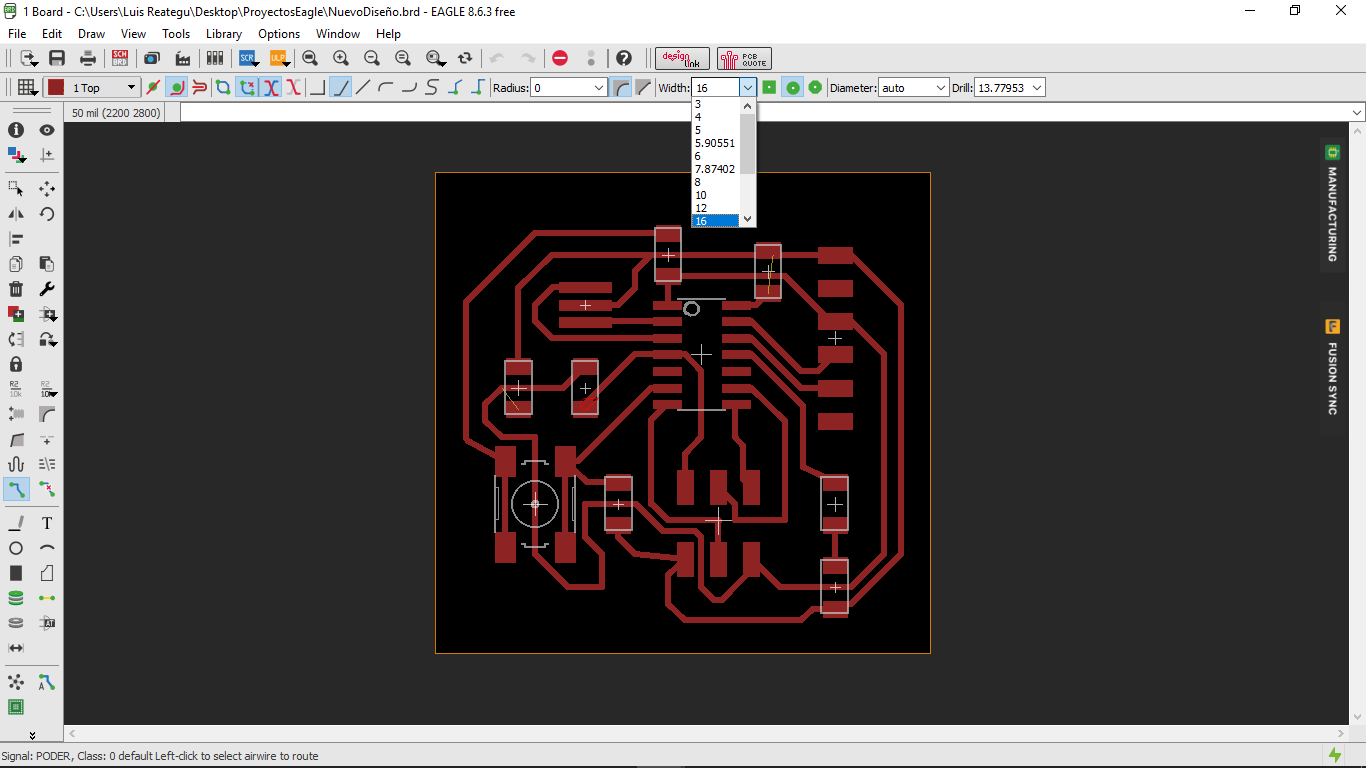
For use Eagle in my design, first I was setup the variables in DRC dialog, when I configured the distance between the pads and wires.
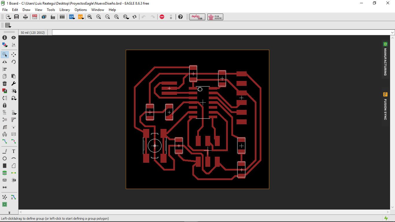
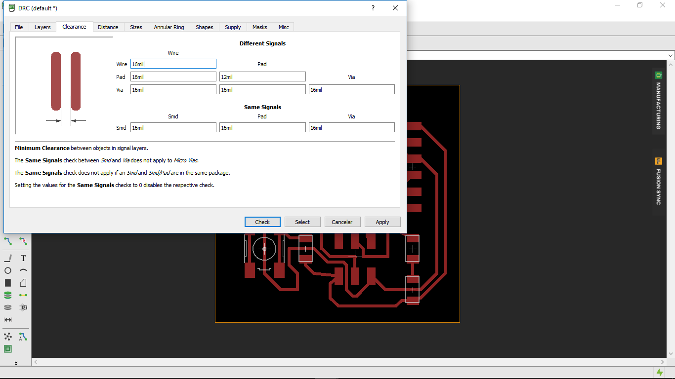
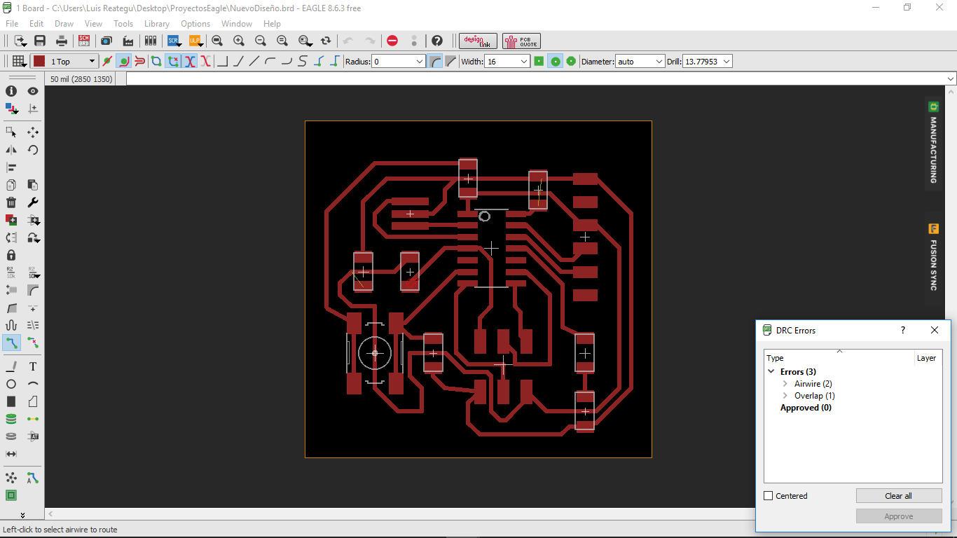
The Pcb Design needs an check with DRC Error Dialog.
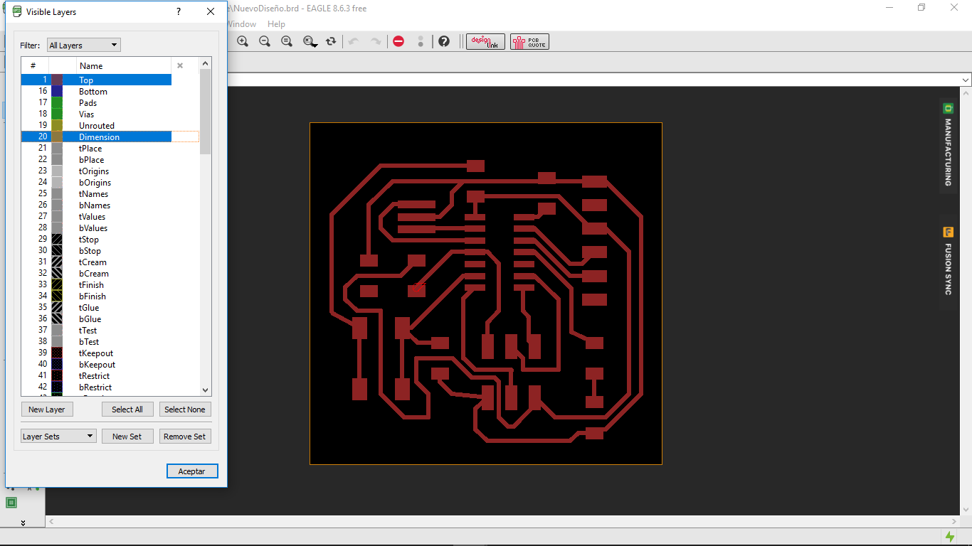
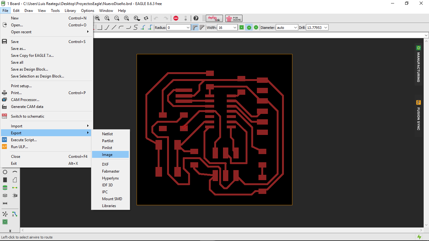
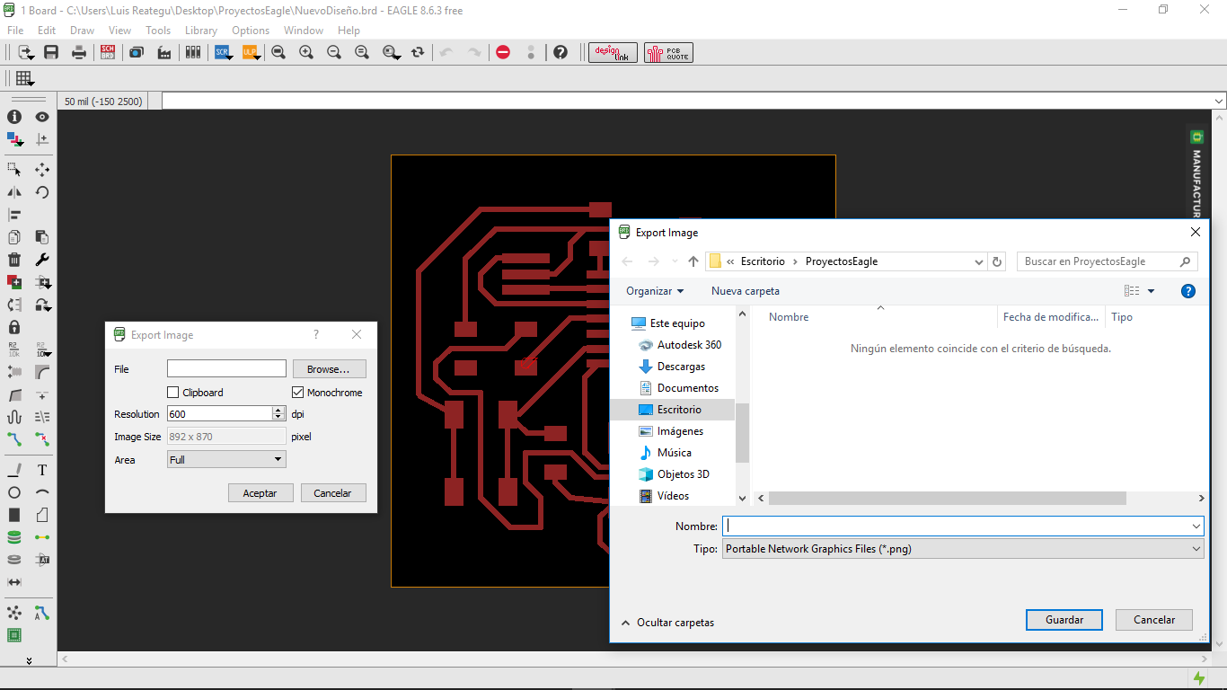
Export the Pcb Design in two Layers, the first one have the pads and wires, and the second have the Pcb edge, both have only two colors, black and white.
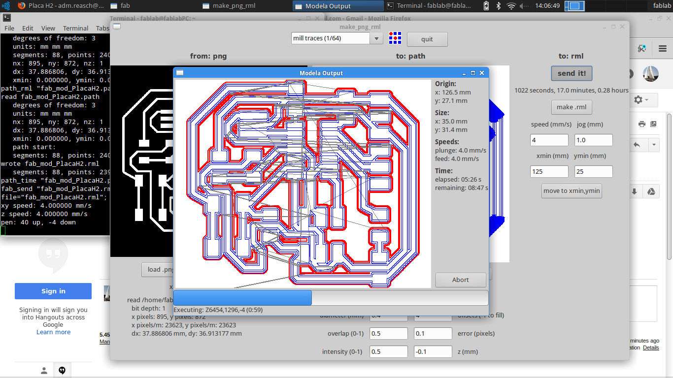
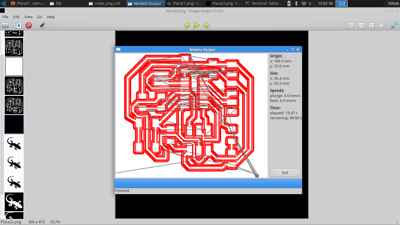
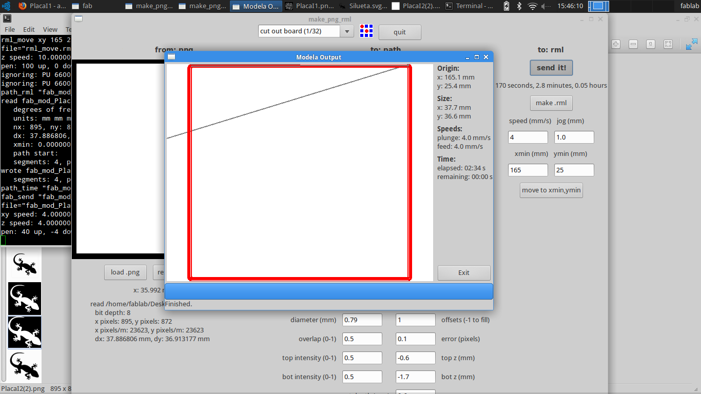
Pcb Digital Fabrication with Roland MDX and Fab Software in Linux
To enter the program We use the terminal in Linux, and write the following commands: 1. Sudo fab. 2. Enter the password
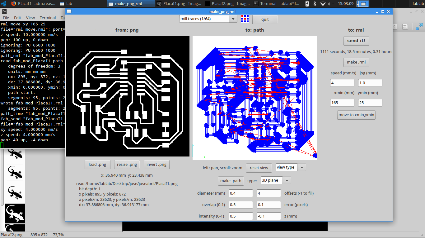
Prepare the Design with the correct Fab configuration. The main variable its the mill traces = 1/64 for pads and wired, and 1/32 for cut the board.
To make the pcb board, We need the followings components:
1. ATTiny 44SSU (1)
2. PushButton (1)
3. Resonator 20 mHz (1)
4. Isp Connector (1)
2. Res 1k (1)
3. Res 10k (1)
4. Led smd (1)
5. Res 499 ohm(1)
6. Empty PCB board to make the circuit
7. 1/32 and 1/64 Drill