Week 8
Make an in-circuit programmer by milling the PCB
Electronics Production. Have you:
- Shown how you made and programmed the board
- Explained any problems and how you fixed them
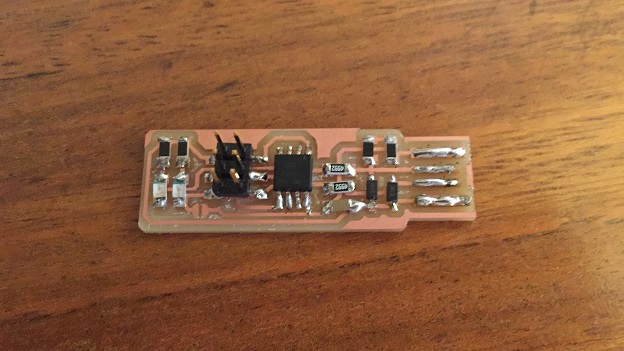
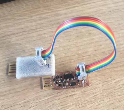
- Included a ‘hero shot’ of your board
The group page assignment is:
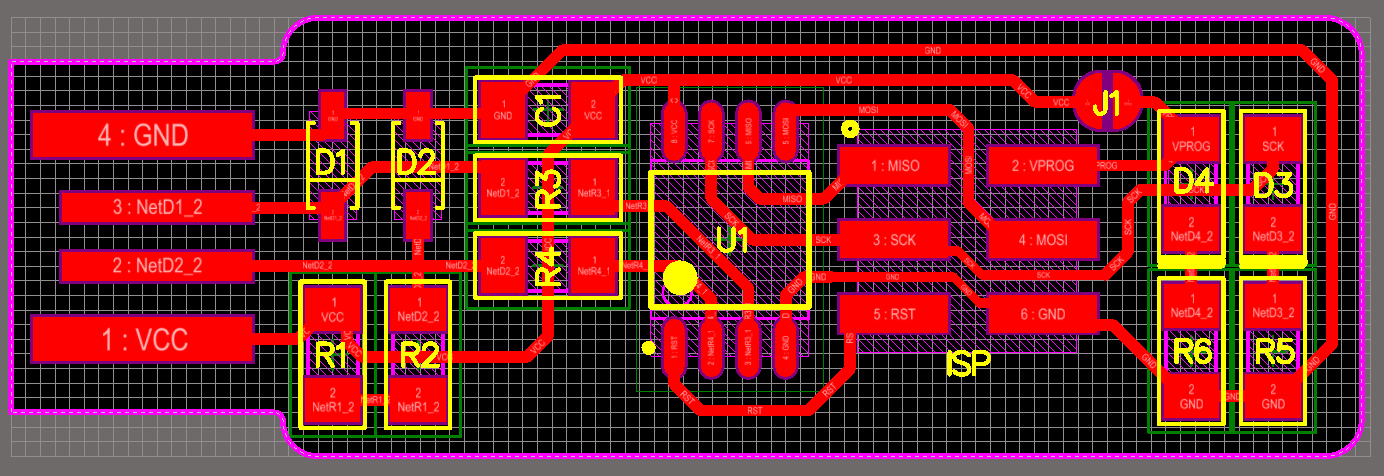
Group Assignment PageChoose the board

Download the information Schedule
Prepare the Milling-Hardware
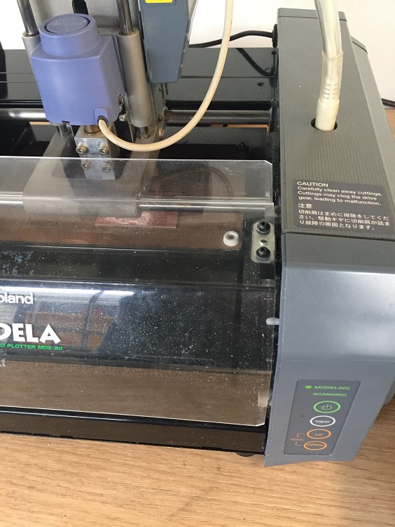
- 1. Adjust the milling machine-Roland--define the milling tool.
- 2. Adjust the tool.To adjust the milling tool in the Roland, use the hexagonal key and adjusted or unadjusted the bolt. It means, first unadjusted to put the 1/64 or 1/32 milling tool, and after that, adjusted the bolt
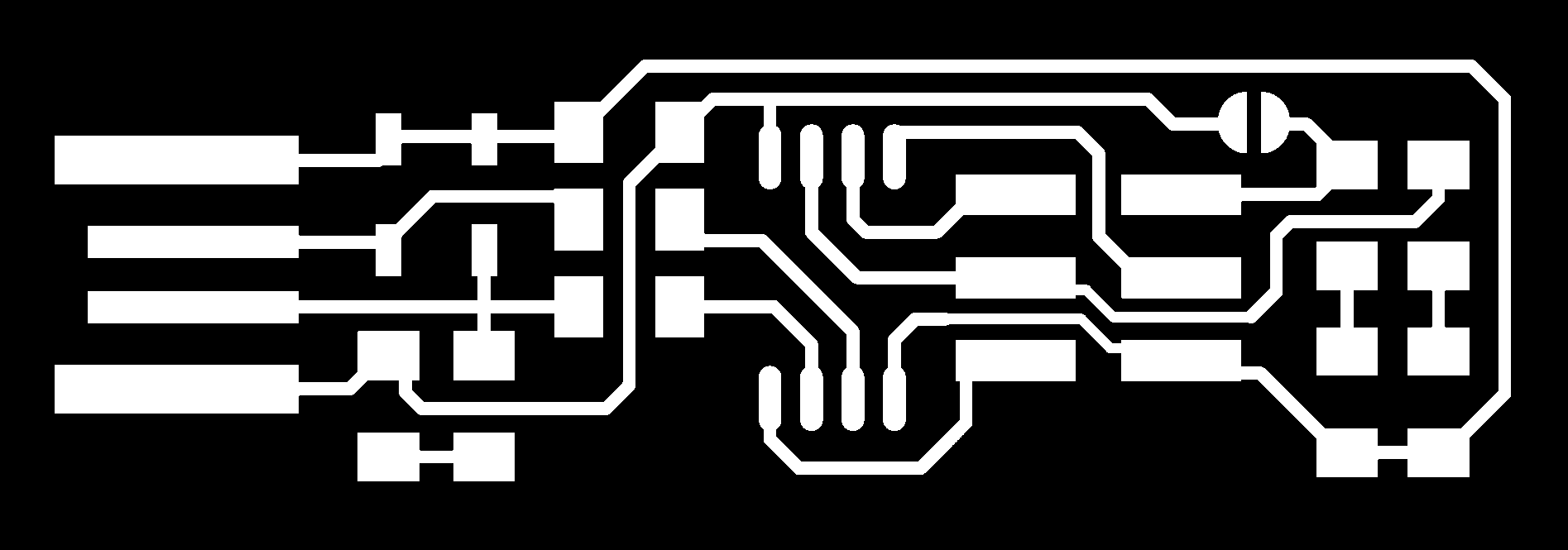
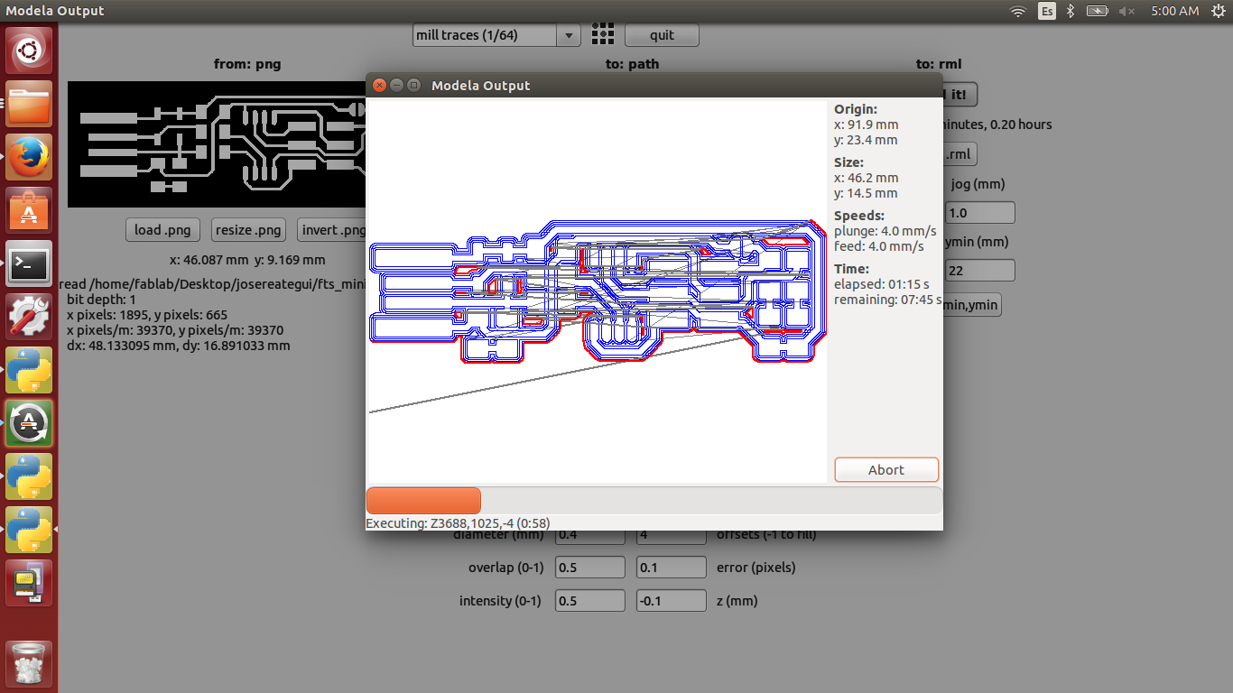
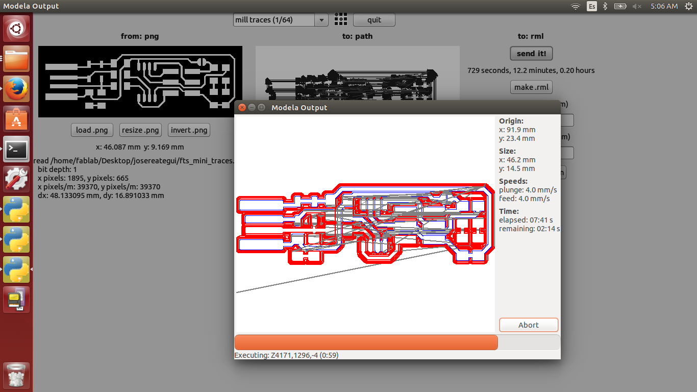
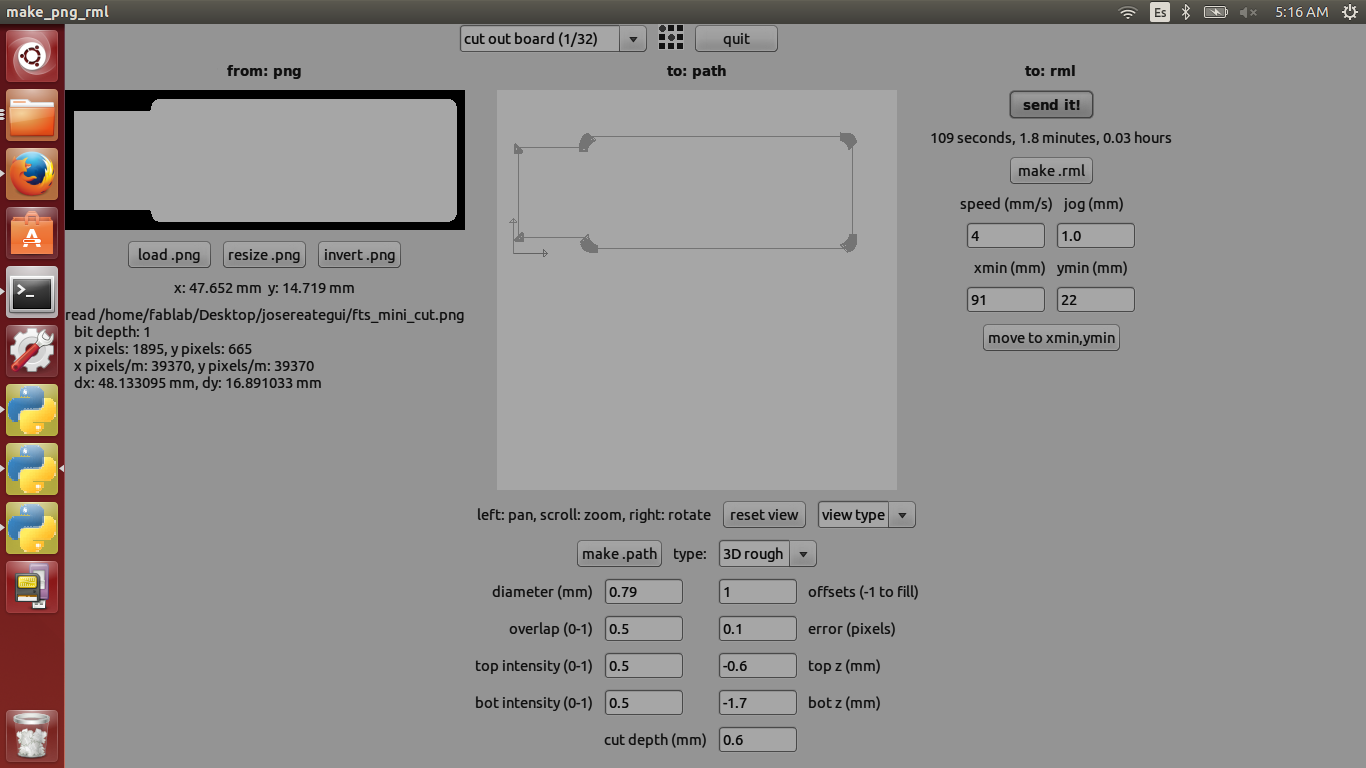
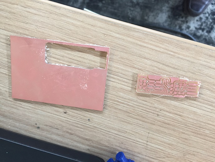
- 3. Define the milling path. To define the milling path we need to know which way we are going to make, if we are going to make the machine of the tracks we have the option that is in the upper part "traces of mill 1/64", if what we are going to do is cut the edge of the board we have to choose the 1/32 "router. It is important to make this change because the distance set between the tracks is related to the milling tool to be used. We can not use the 1/32 "milling tool to make the tracks
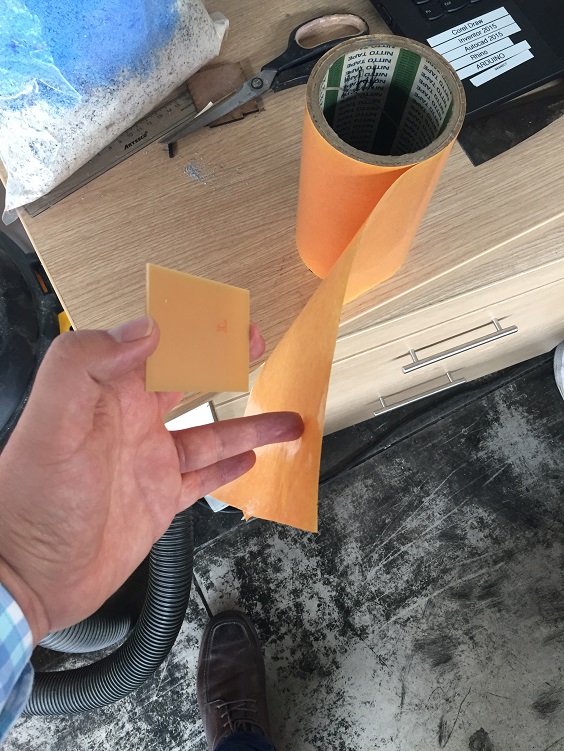
- 4. Prepare the clear boardTo be able to use the Roland on the card, the first thing we have to do is fix the card to the bed of the Roland with double contact tape, then make sure it is fixed with a little pressure
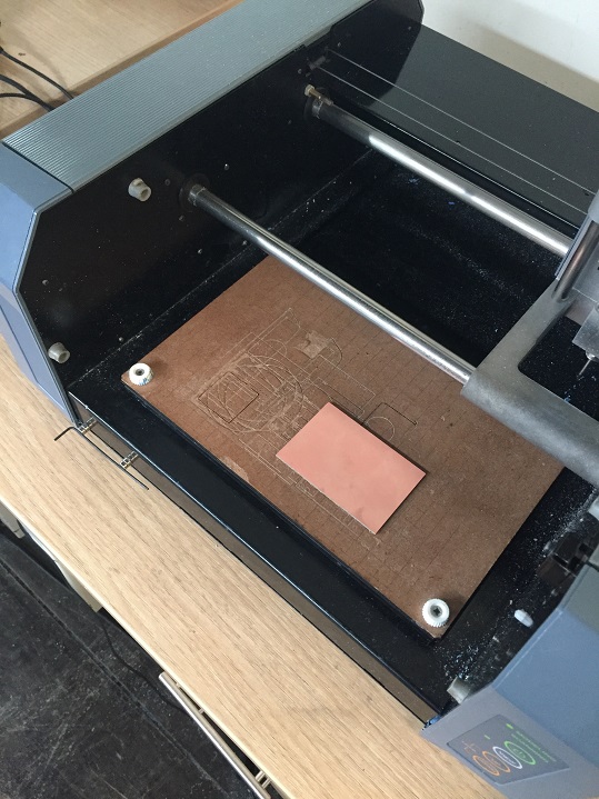
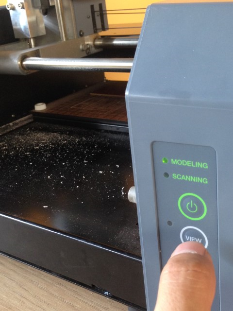
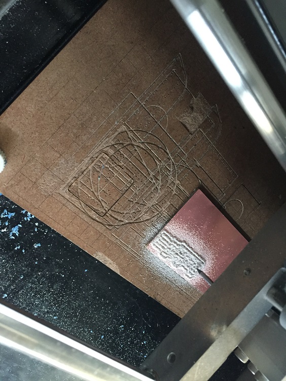
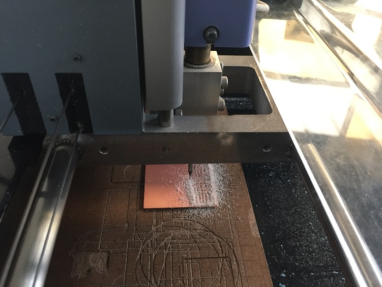
- 5. The Roland milling machine works.
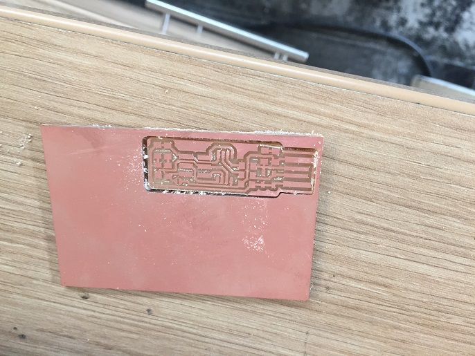
- 6. The final PCB .We must ensure that the final result has the characteristics of required conductivity, that is to say that there are no unwanted connections between tracks, this is done with the multimeter
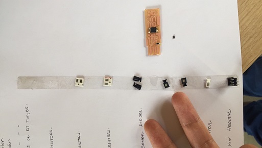
- 1. Prepare the list of componentsIt is important to place a double-contact adhesive tape to place the components and prevent them from being lost.
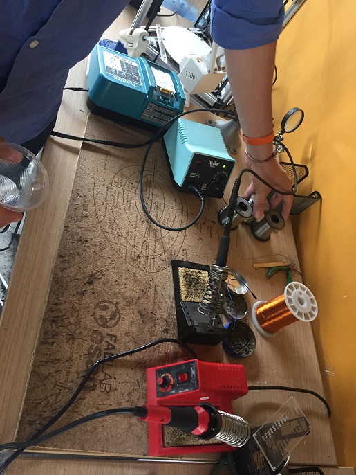
- 2. Prepare the solder station--The work zone consists of a welding station with its cleaning sponge, magnifying glasses to check the solder, tin to join the components to the board, transformers that allow to protect the electrical network, clamps to manipulate the components, multimeter to know the continuity of the circuits
- 3. Solder the componentsTo weld the components it is good that we consider the following steps:
- Solder the processor, because the pins are very close to each other, it is advisable to start with the pins in the center and then the external pins
- solder the resistors and capacitors for being small components
- Solder the Ftdi and ISP connections, starting with the pins that are near the center and at the end end
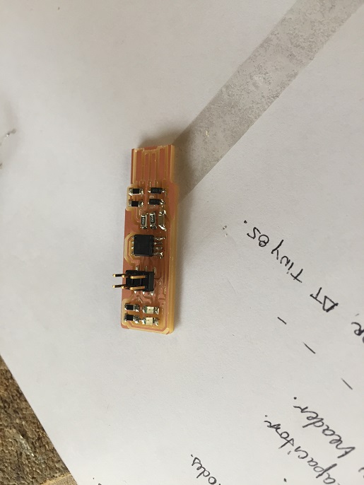
- 4. Final board solder--This board use Attiny 45
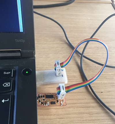
- 5. preparing the board to receive the software--We need to use the ISP Cable to program
- Atmel Studio
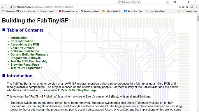
- FabIsp Programming Page
To define the milling tool We need to considerer if We used 1/64 or 1/32 tool, to mill traces use the 1/64 mill tool. To make the board edge use the 1/64 milling tool.

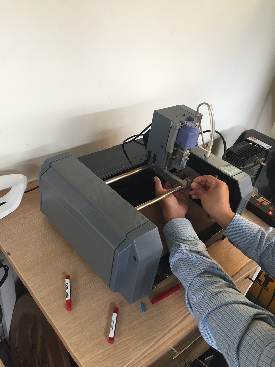
You have to be very careful when calibrating the height of the milling tool because these are very susceptible to break. It is advisable to press the button on the bottom left until 5 mm is missing, after that it is necessary to lower the pulses that allow to lower in a controlled manner. To determine how much of the food should go into the plate I recommend making a sharp view of the waste that will be produced. The first resulting residues marked the limit of the milling tool .
Soldering the components
We need to program the USBTinyISP .
We need to connect a FabIsp to other FabIsp that need the program
Install WinAVR
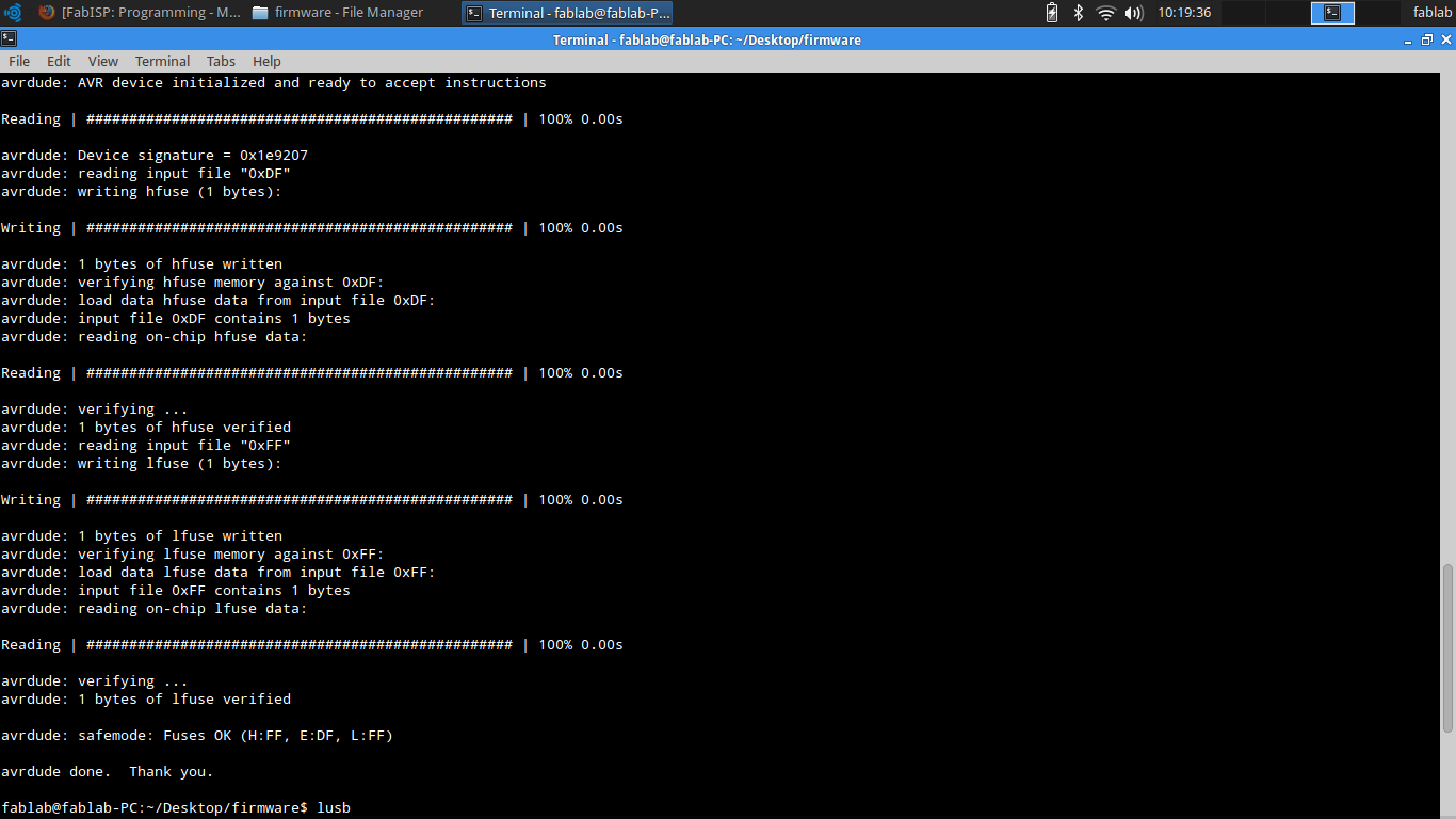
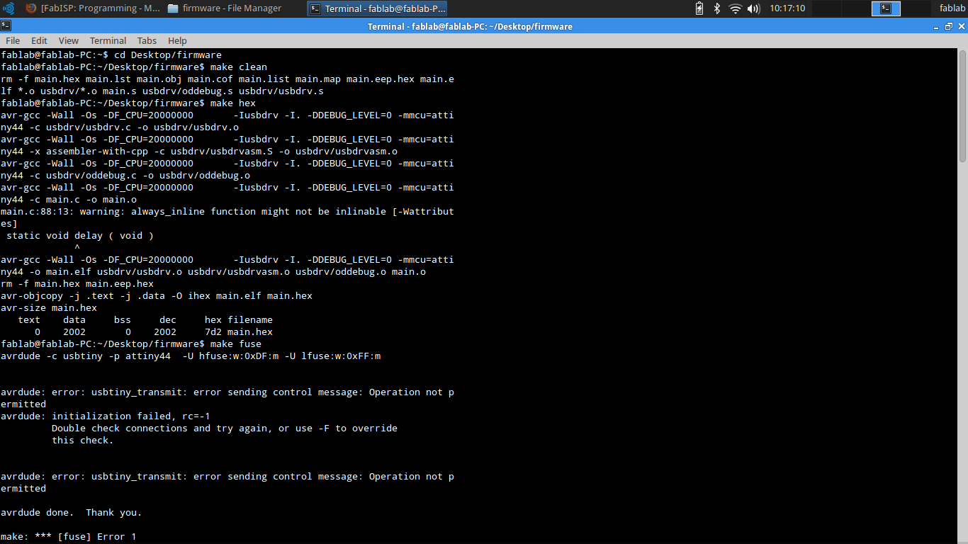
Make this program with the following commands
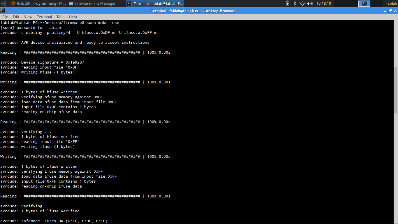
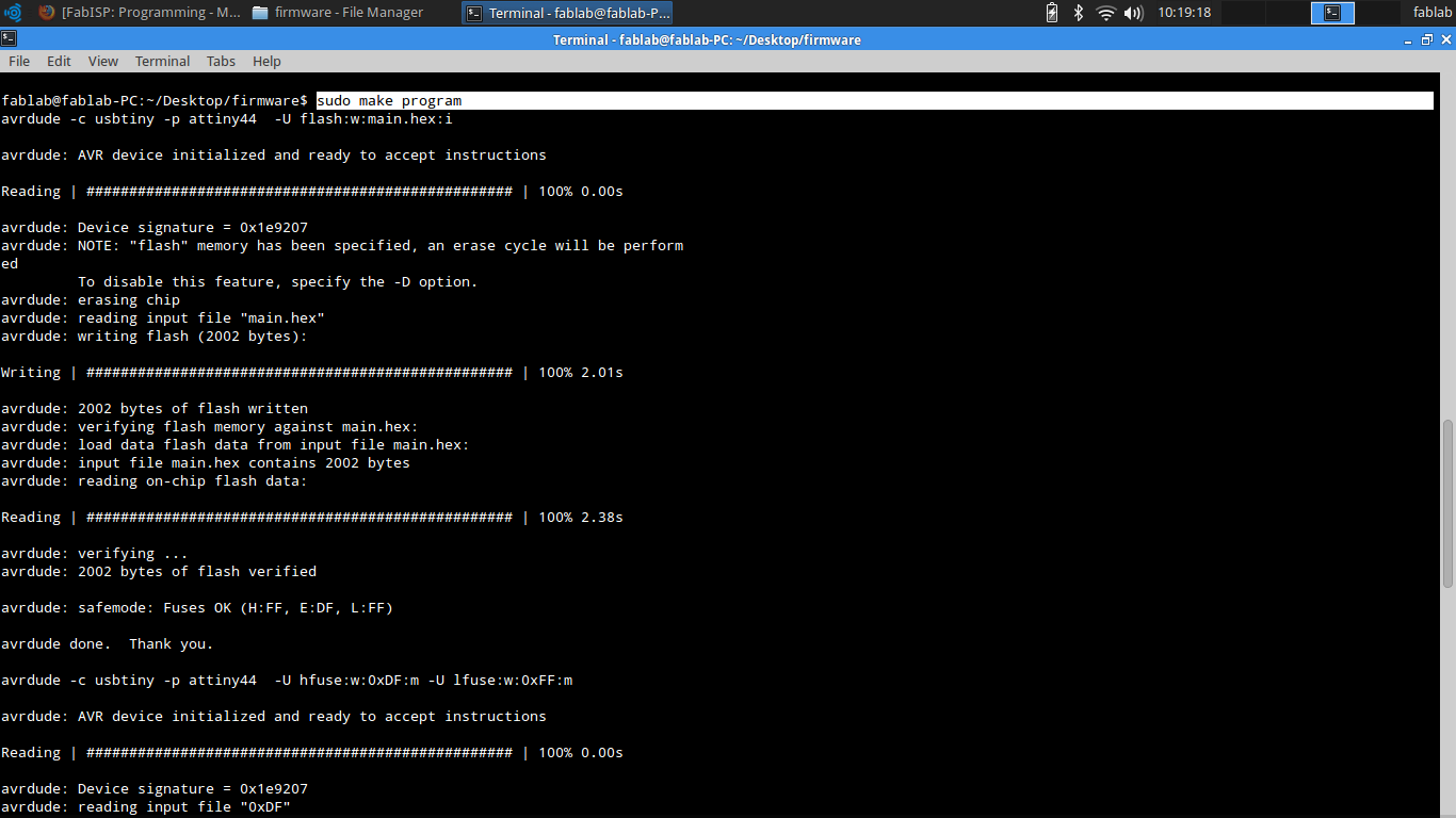
For more references please check this site