week 9
Output Devices
Output Devices. Have you:
- Described your design and fabrication process using words/images/screenshots.
- Explained the programming process/es you used and how the microcontroller datasheet helped you.
- Explained problems and how you fixed them
- Included original design files and code
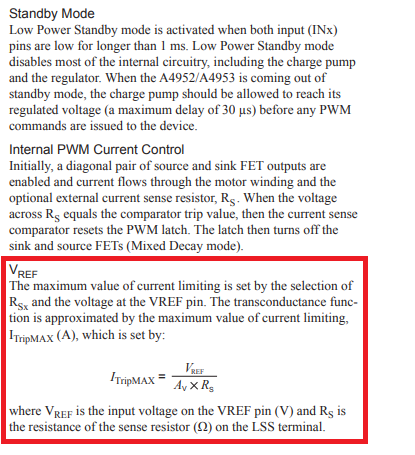
First one, I need to know the A4953 features. Then the Data-Sheet is necessary to know how can We use this motor driver, and how connect it.
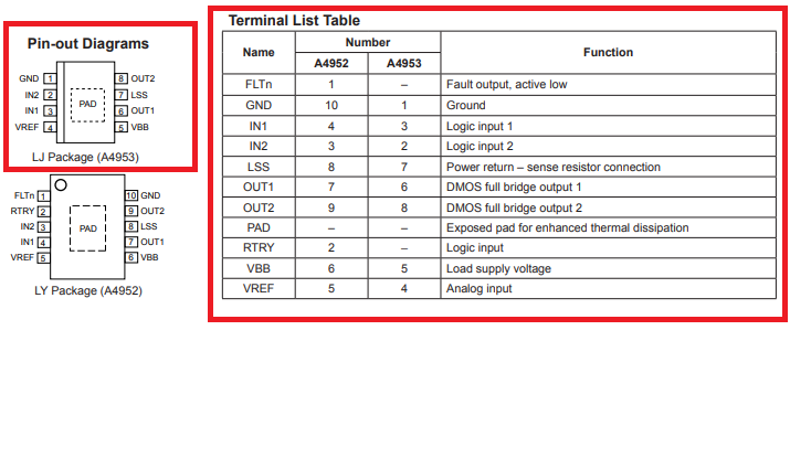
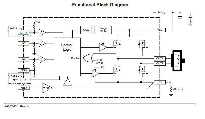
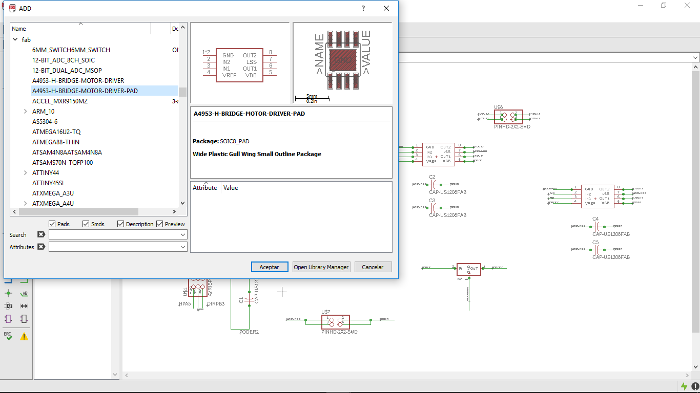
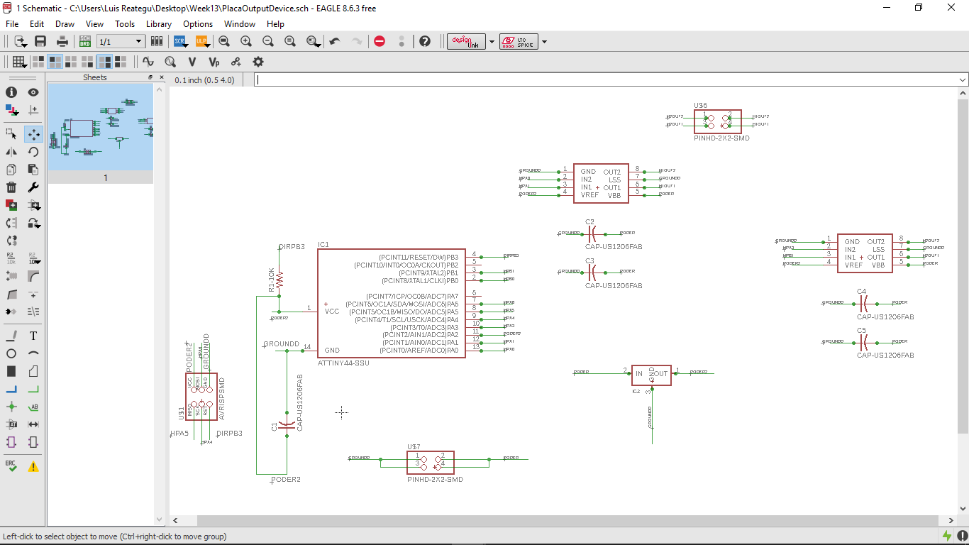
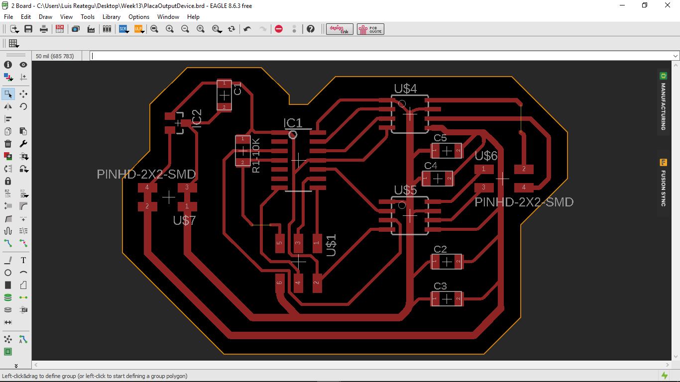
We need to Design the board in Eagle Software, and include the electronic component in the schematic with A4953-H-Bridge-Motor-Driver code in Fab library.
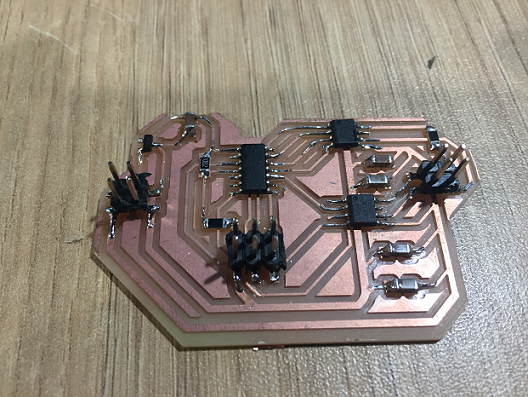
The Design uses the FTDI connector and a ATtiny 44 SSU, and was create with 16mm wire design
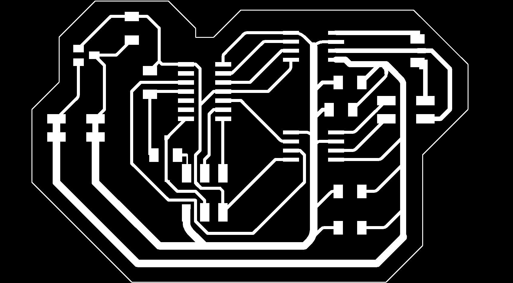
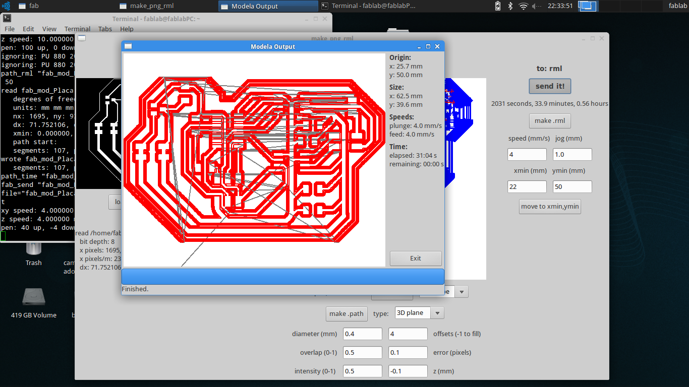
To manufacture the card it was necessary to export in .png format, then use the Roland MDX and follow the process described in the assignment "Electronics production"

Components that We need:
- ATtiny44 micro-controller
- AVRISPSMD connection-Pin header 2x3
- FTDI Connection-Pin header 1x6
- 1 Resistor 10K
- 3 Capacitor 1uF
- 2 Capacitor 10uF
- 2 A4953 Motor Driver
Explained the programming process/es you used and how the microcontroller datasheet helped you.
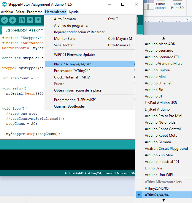
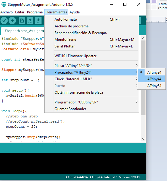
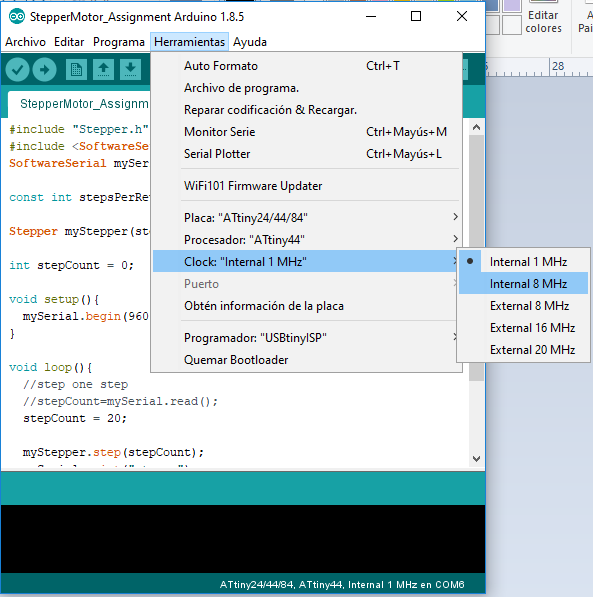
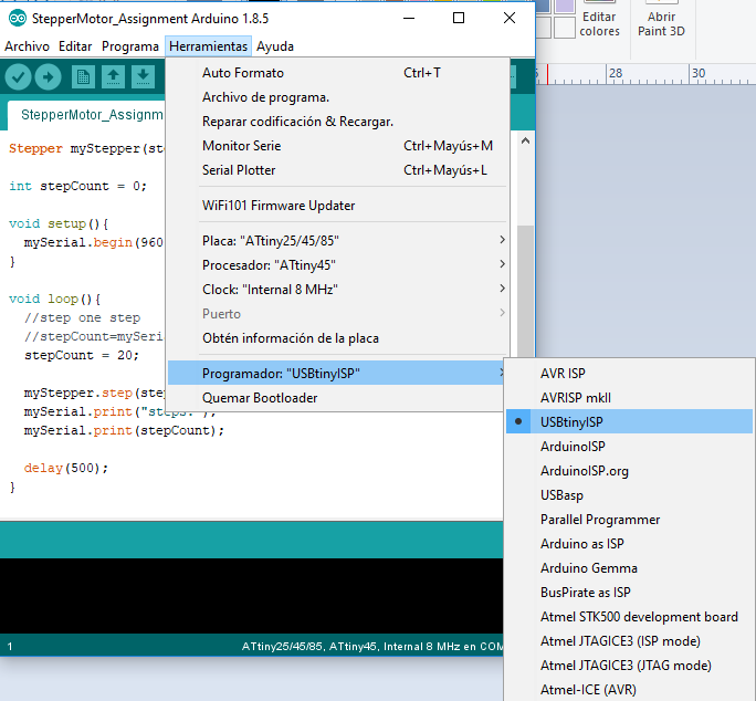
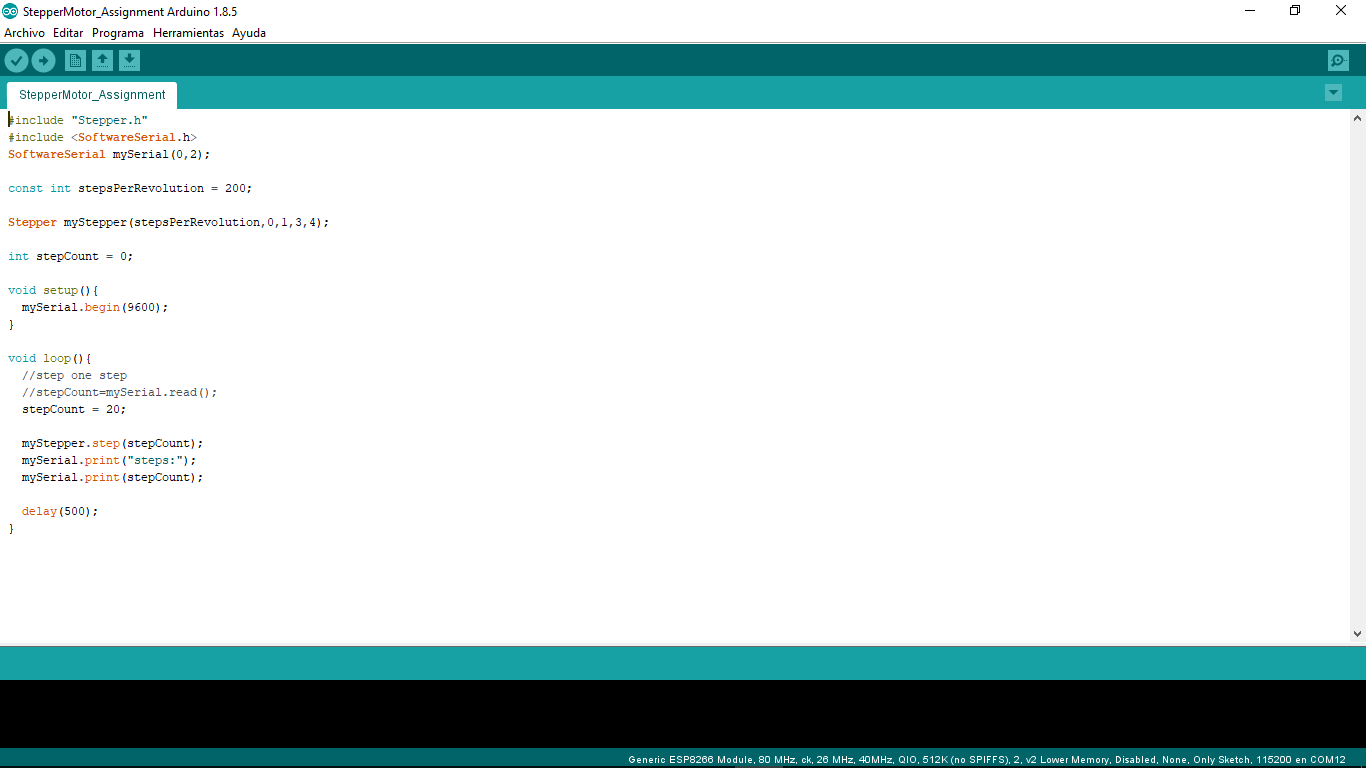
We will use the FTDI cable to program, and insured that arduino mark the serial monitor "COM". We choose the ATtiny44 processors menu. Then we choose the ATtiny44 processor, which is the one with our board, then we choose the clock if we do not have a clock, we choose the 8mhz number. Finally we choose the Programmer, in our case the USBTinyISP
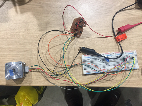
The test used Serial Monitor to 1200 Baudio and the signal from FTDI cable
This video link have the demo.
OutputDevices from JOSE LUIS REATEGUI on Vimeo.
Explained problems and how you fixed them
The biggest problem with working with this board is how the electricity is distributed in the circuit, basically there are two flows of electricity, the first is directed to power the motors and the second to power the processor and drivers, it is very important to separate and connect properly these flows because wrong can damage the processor