Assignment 12: Output Devices
Add an output device to a microcontroller board you've designed and program it to do something
Learning outcomes:
Demonstrate workflows used in controlling an output device(s) with MCU board you have designed.
Group assignment:
Measure the power consumption of an output device.
Document your work to the group work page and reflect on your individual page what you learned.
Individual assignment:
Add an output device to a microcontroller board you've designed and program it to do something.
For this assigment I chose to design a PCB that has connected as output device a Buzzer that emits a sound and a led that changes color. The buzzer and the led would activate when detecting the presence of objects or people near the PCB. I chose to place an ultrasound sensor on the PCB to obtain different readings of approximating objects. In the same way I programmed the processor so that this information transforms it into sound. Additionally I placed a led to verify the operation of the PCB.
Step 1: I checked the documentation about Output devices on the Fab Academy website. I put special interest in knowing how the Speakers work: video, board, components.
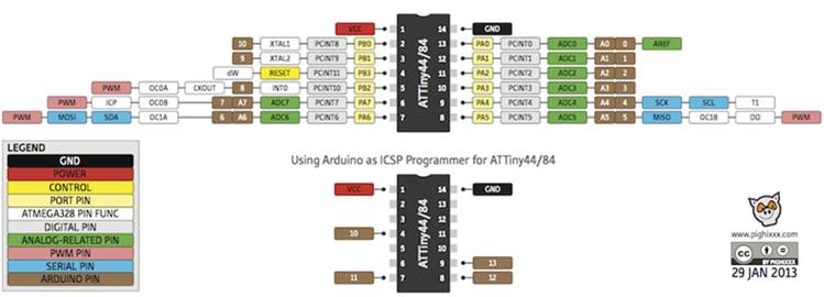
Step 2: Next, check the Attiny44 processor datasheet to see how each of the pins can be used:
Step 3: Next I design the PCB using the Eagle program. In design I used the following components:
1 Attiny 44 Processor
1 uF capacitor
1 RGB LED
3 499 ohm resistors
1 pin header FTDI
1 pin ABRISP
1 pin header of 2x2
3 0k resistors
1 2x3-inch PCB board
1 ultrasound sensor HC-SR04
1 Fab ISP programmer
1 USB FTDI cable
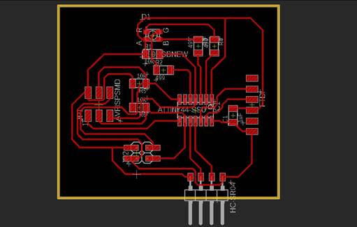
Step 4:In the Eagle program I organized the components. The 1 uF capacitor is connected to the VCC and GND pins before it reaches the processor. The 499 ohm resistors are connected to the cathodes of the led The buzzer will be connected to the GND and SDA pins.
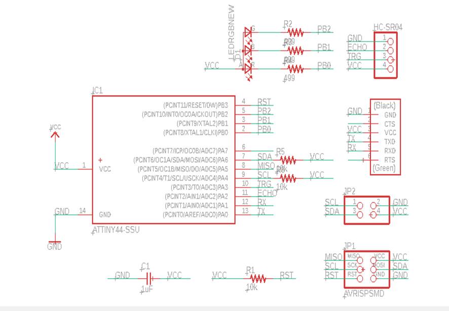
Step 5: Then I organized the components around the processor and created the clues that join all the components. It was necessary to create three bridges with 0 ohms resistors. The PCB was designed as follows:
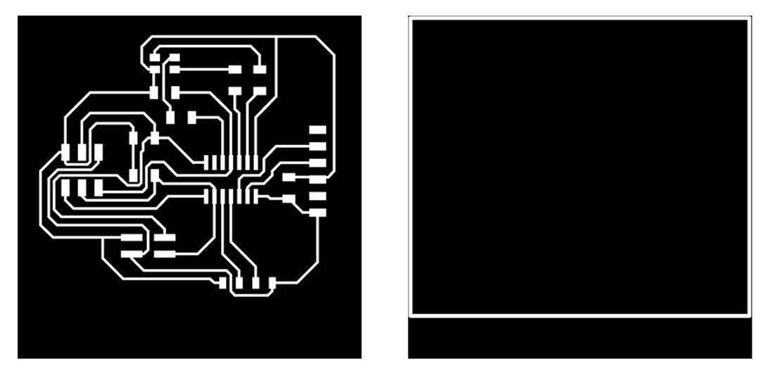
Step 6: Next I export the traces and exterior images::
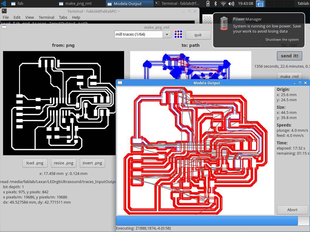
Step 7: The cards were then milled using a Roland Modela MDX 20 milling machine. For the milling of the PCB, 1/64 and 1/32 cutters were used.
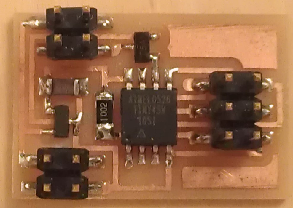
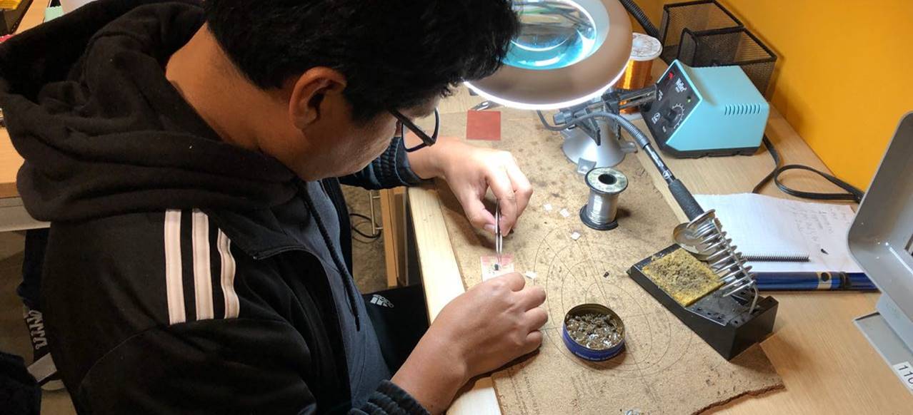
Step 8: The components of the PCB were then welded according to the schematic previously designed in the Eagle program.
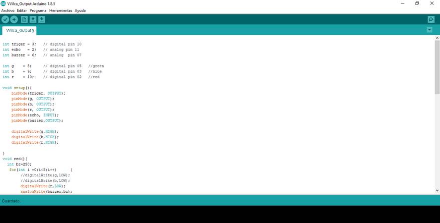
Step 9: To program the PCB I used the Arduino program. Use the following pins to define the triger, echo, buzzer and the colors of the LED pins:
int triger = 3; // digital pin 10
int echo = 2; // analog pin 11
int buzzer = 6; // analog pin 07
int g = 8; // digital pin 05 //green
int b = 9; // digital pin 03 //blue
int r = 10; // digital pin 02 //red
Step 10: Next, in the SetUp function, I defined how each of the pins will be used:
void setup(){
pinMode(triger, OUTPUT);
pinMode(g, OUTPUT);
pinMode(b, OUTPUT);
pinMode(r, OUTPUT);
pinMode(echo, INPUT);
pinMode(buzzer,OUTPUT);
digitalWrite(g,HIGH);
digitalWrite(b,HIGH);
digitalWrite(r,HIGH);
Step 11:Then I defined a function for two colors that I would use in the PCB: red and yellow:
void red(){
int bz=250;
for(int i =0;i<5;i++) {
digitalWrite(r,LOW);
analogWrite(buzzer,bz);
bz = bz - 60;
delay(50);
digitalWrite(r,HIGH);
delay(50);
}
analogWrite(buzzer,0);
};
void yellow(){
analogWrite(buzzer,30);
for(int i =0;i<5;i++) {
digitalWrite(g,LOW);
digitalWrite(r,LOW);
delay(50);
analogWrite(buzzer,0);
digitalWrite(g,HIGH);
digitalWrite(r,HIGH);
delay(80);
}
};
Step 12: Then in the Loop function I programmed the processor so that if an object comes closer between 10 and 20 cm, a low volume sound will be emitted and a green LED will light up. In the Loop function, I programmed the processor so that if an object approaches between 0 and 10 cm, a high volume sound will be emitted and a red LED will light up.
void loop(){
float duration;
int distance=0;
digitalWrite(triger,LOW);
delayMicroseconds(2);
digitalWrite(triger,HIGH);
delayMicroseconds(10);
duration = pulseIn(echo,HIGH);
distance = round(duration*340/20000.0); // distance in cm
if (distance<10) {
red();
}
else{
if (distance <20){
yellow();
Step 13: Next, I connect the programmer to the PCB through the ISP output:
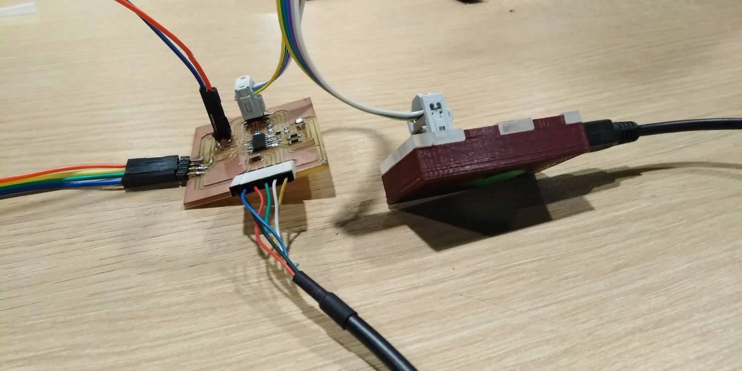
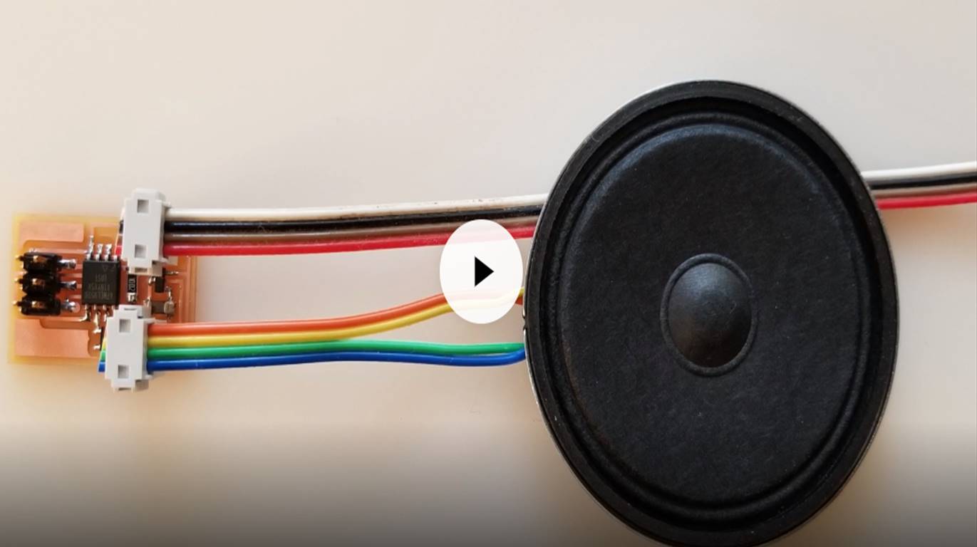
Step 14:Finally, I uploaded the program to the PCB and checked the operation of the PCB and the components.