Week 11
Output Devices
Assignment
Group
• measure the power consumption of an output device.
Individual
• Add an output device to a microcontroller board you've designed and program it to do something.
Group Assignment
For this assignment I measured the power consumption of the solenoid valve. I used the arduino uno to connect the solenoid valve and added an led to test the opening and closing of the solenoid. I connected the valve to the power supply.
Power consumption(watts) = Current (A) multiplied by Voltage (v)
(268/1000) A * 12V = 3.216 Watts
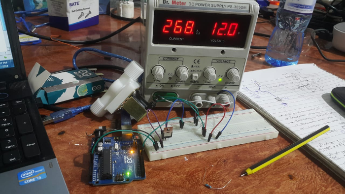
The led blinks as the solenoid valve opens and closes.
Neopixel LED
This multi-color LED contains red, green, and blue elements that can be mixed to produce any color. Unlike many other RGB LEDs, this unit has a diffused white lens that blends the colors without any additional diffusers or reflectors.
WS2812B is a intelligent control LED light source that the control circuit and RGB chip are integrated in a package of 5050 components. It internal include intelligent digital port data latch and signal reshaping amplification drive circuit. Also include a precision internal oscillator and a 12V voltage programmable constant curre-nt control part, effectively ensuring the pixel point light color height consistent.
The data transfer protocol use single NZR communication mode. After the pixel power-on reset, the DIN port receive data from controller, the first pixel collect initial 24bit data then sent to the internal data latch, the other data which reshaping by the internal signal reshaping amplification circuit sent to the next cascade pixel through the DO port. After transmission for each pixel,the signal to reduce 24bit. pixel adopt auto resha-ping transmit technology, making the pixel cascade number is not limited the signal transmission, only depend on the speed of signal transmission.
LED with low driving voltage, environmental protection and energy saving, high brightness, scattering angle is large, good consistency, low power, long life and other advantages. The control chip integrated in LED above becoming more simple circuit, small volume, convenient installation.
For this assignment I decided to do the multi colored LED as my output device since it was already available in our lab. The LED has three different colors the red, green and blue am planning to program it to blink different colors at an interval.
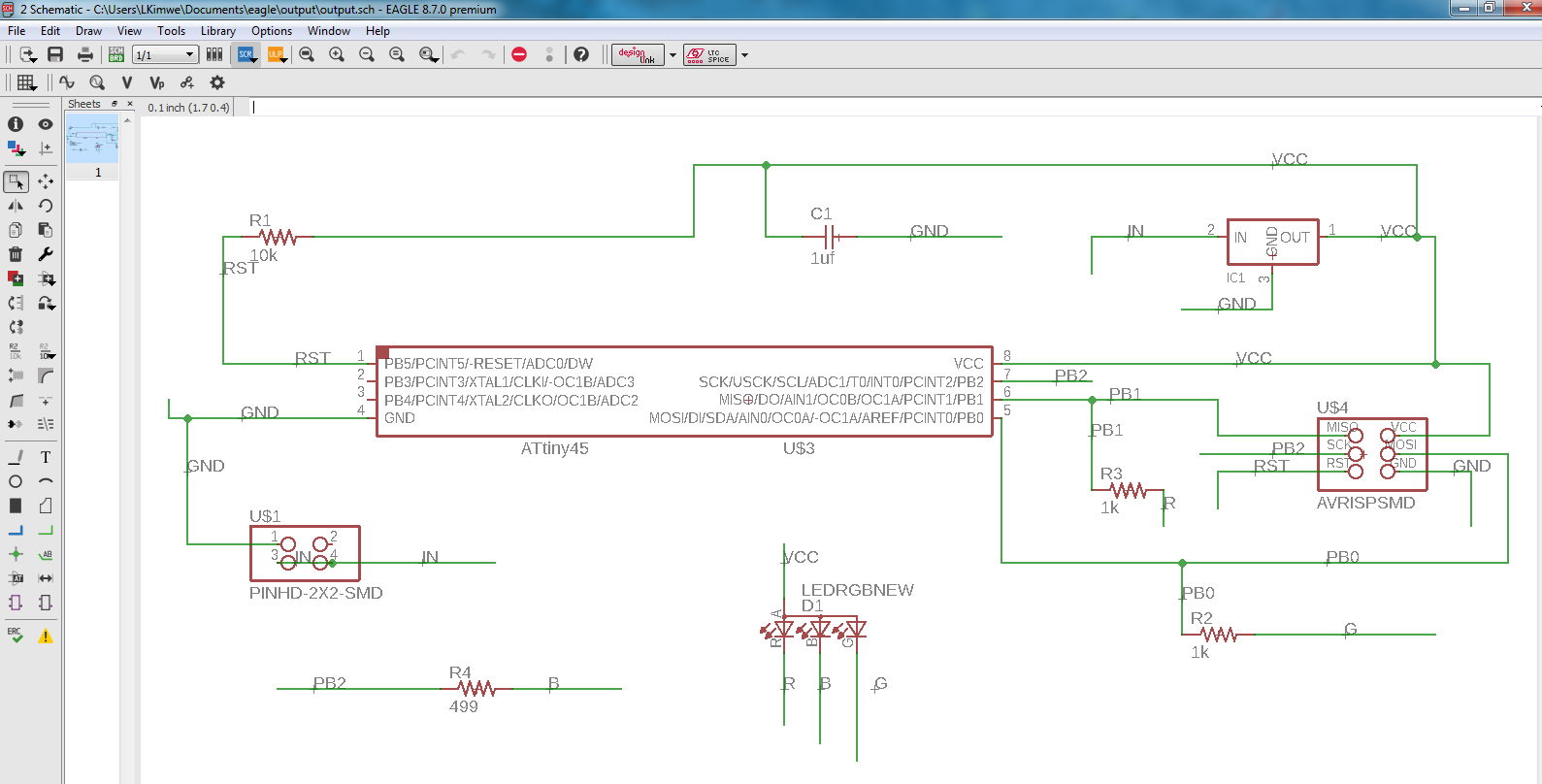
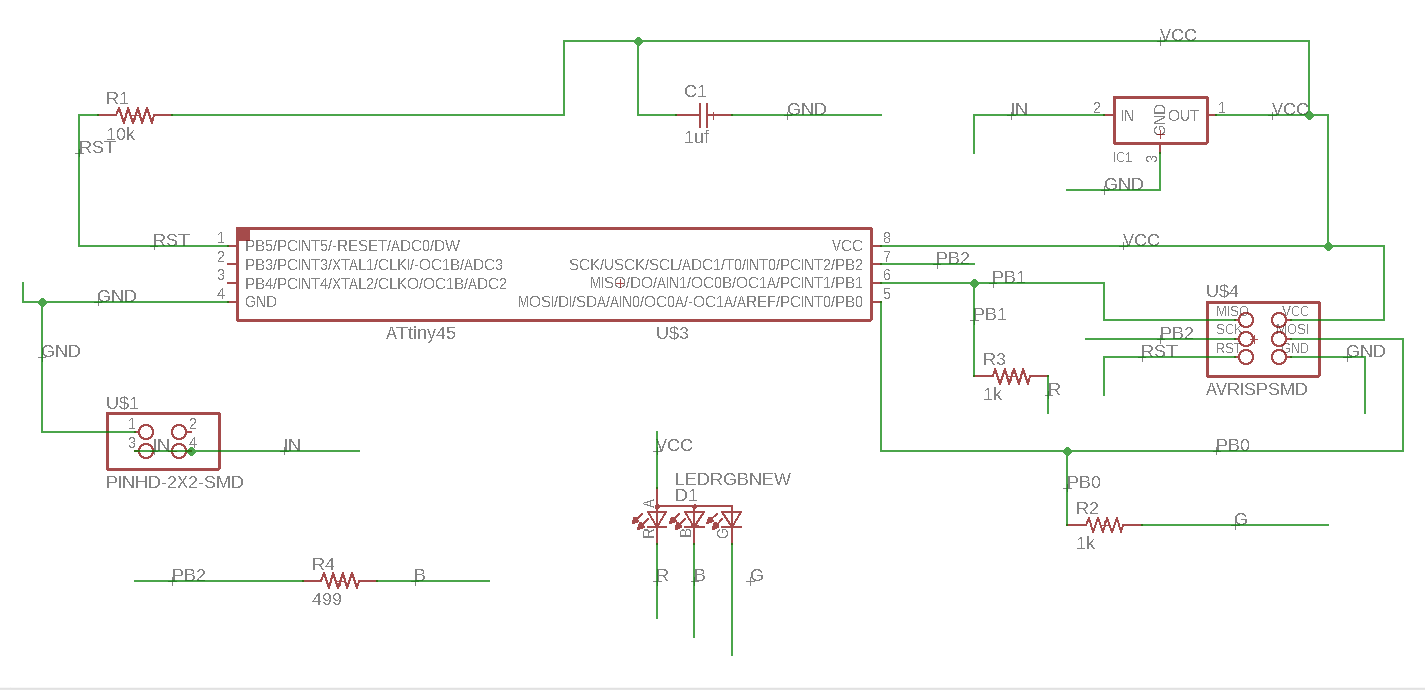
Schematic design
I used Eagle which I have gotten familiar with too design the board for the components I used the components from the fab library that I had importred as a library in th software. Started by first creating a new project then I created a new schematic by creating right clicking the project then new project. Then I used the add components button to add the components I needed. Then connected the components using the green connector tool and gave it the necessary labels as shown.
How the datasheet helped
The datasheet came in handy in knowing the connections of the pins of the microcontroller.
What followed was the screen board for it that I generated using this button. I gave the board dimension of 50 by 50 mm, rearranged the components inside the box by dragging them. used the rotation button to put them in the direction I wanted them to face using this button.
 The routing tool to route manually the connections.
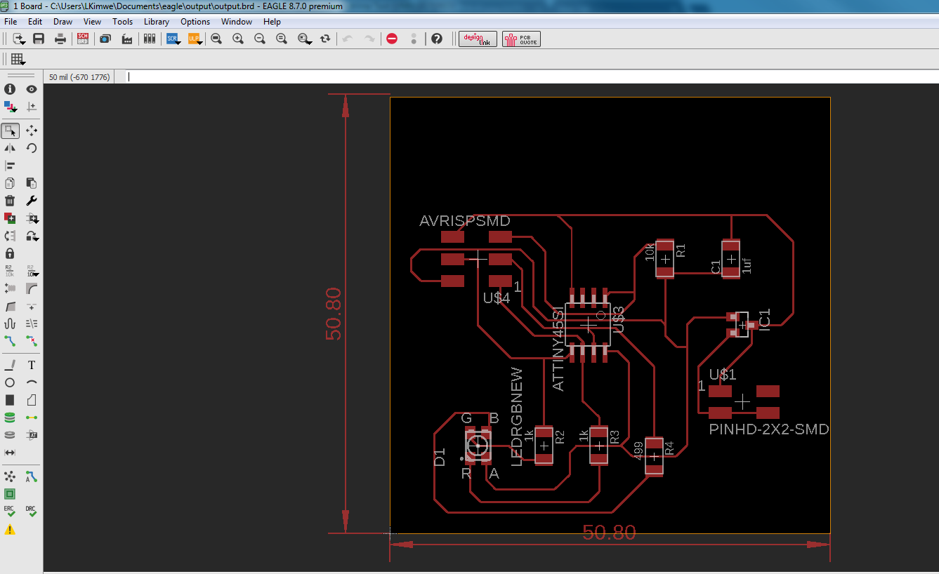
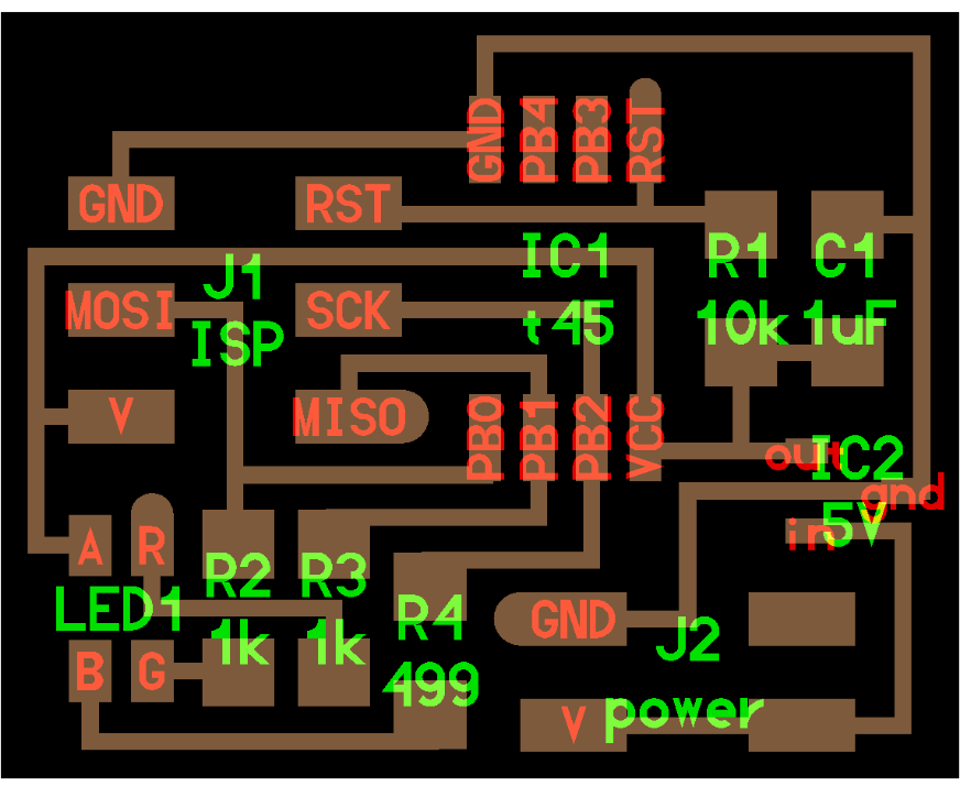
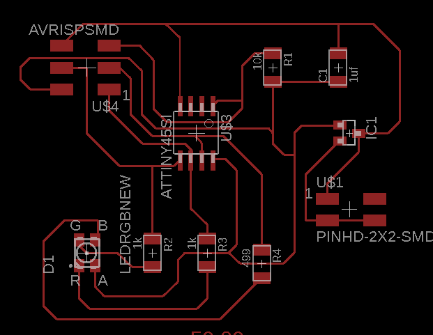
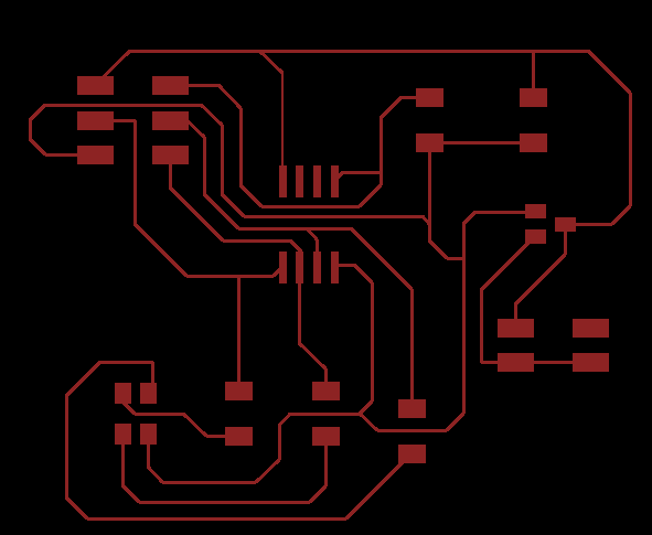
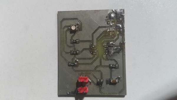
Once done routing this is how the board look like.
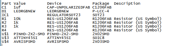
Components
I learned from my colleagues for you to be able to able to mill or etch you have to remove the dimensions, writtings and the silks for the components or else it will short circuit. I used the layer setting tool to remove them. For the dimension I had to remove manually.
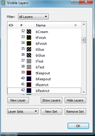
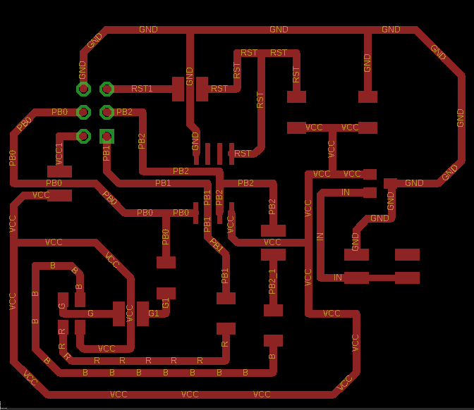
This is how it looks like once I remove most of the layers.
Before
After
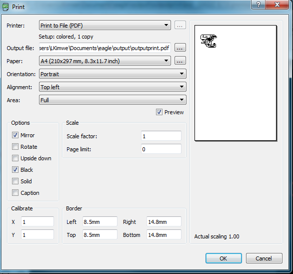
This is the screen to help print out the design to pdf so that I can print it.
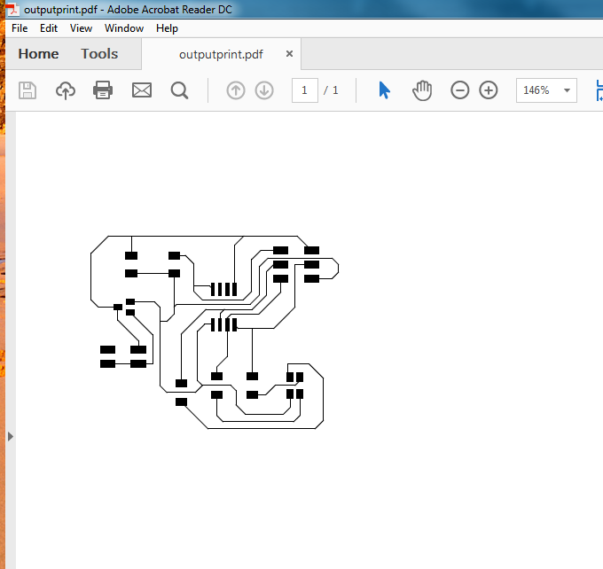
The printed version of the design.
Challenges
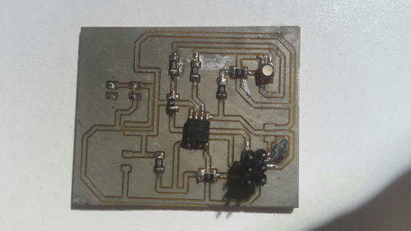
The tracks for the board where too thin and endded up breaking hence cutting out continuity of the connections . I redid the tracks a gain with a thicker mm line.
Before
After
Programming
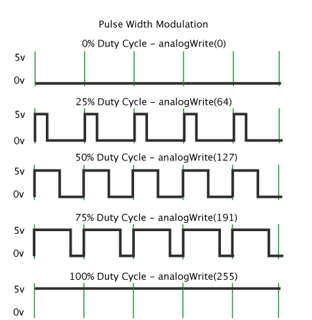
Pulse Width Modulation
Pulse Width Modulation, or PWM, is a technique for getting analog results with digital means. Digital control is used to create a square wave, a signal switched between on and off. This on-off pattern can simulate voltages in between full on (5 Volts) and off (0 Volts) by changing the portion of the time the signal spends on versus the time that the signal spends off. The duration of "on time" is called the pulse width. To get varying analog values, you change, or modulate, that pulse width. If you repeat this on-off pattern fast enough with an LED for example, the result is as if the signal is a steady voltage between 0 and 5v controlling the brightness of the LED.
In the graphic below, the green lines represent a regular time period. This duration or period is the inverse of the PWM frequency. In other words, with Arduino's PWM frequency at about 500Hz, the green lines would measure 2 milliseconds each. A call to analogWrite() is on a scale of 0 - 255, such that analogWrite(255) requests a 100% duty cycle (always on), and analogWrite(127) is a 50% duty cycle (on half the time) for example.
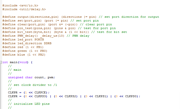
I programmed the board using the code online and the makefile. I used the pwm concept to make a few changes to the code where i delayed it from 25 microseconds at first then to 10 microseconds the second video. The command that I used Avrdude command avrdude -c usbtiny -p t45 -u -U flash:w:rgb.c.hex:i

25 miroseconds
A video of the led blinking
10 microseconds
A video of the button pressed and led blinking faster.