Week 13
Networking and Communications
Assignment
Group Assignment
• Send a message between two projects
Individual
• design and build a wired and/or wireless network connecting at least two processors.
Group Assignment
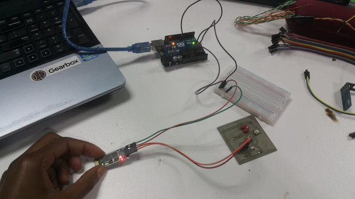
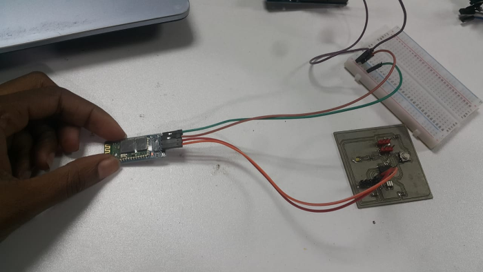
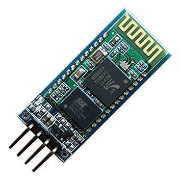
For this assignment I used the bluetooth module to connect to phone's bluetooth. Inorder to accomplish this I used the hello board to connect to the bluetooth module through the ftdi pins. I connected TX pin (bluetooth module) to TX (ftdi pin of the hello board) and RX pin (bluetooth module) to RX (ftdi pin of the hello board). To power the board I used the arduino 5V pin which i connected to a bread board and the GND of the arduino board. Then connected the VCC and GND pins for both the bluetooth and hellow board to the bread board as shown.
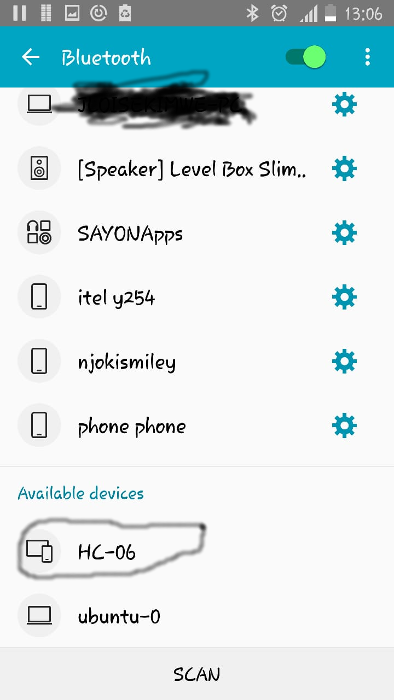
After the connections I used my phone to connect to the bluetooth module. went to the setting then bluetooth as shown it displayed the available devices which in this case is HC-06.
The module has a default password from the manufacturer which I keyed in the password section to enable the bluetooth module to pair with the phone bluetooth.
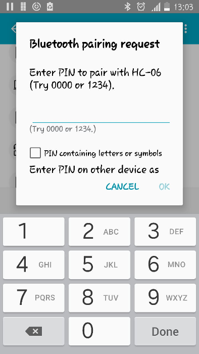
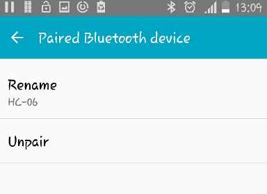
The module successfully paired as shown.
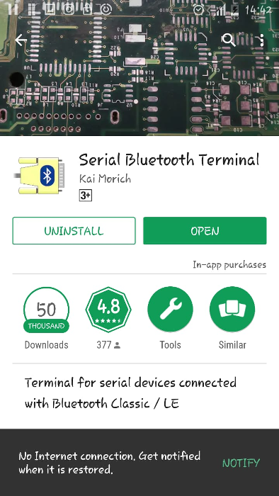
For serial communication I installed an app from play store i.e. Serial Bluetooth Terminalas as shown.
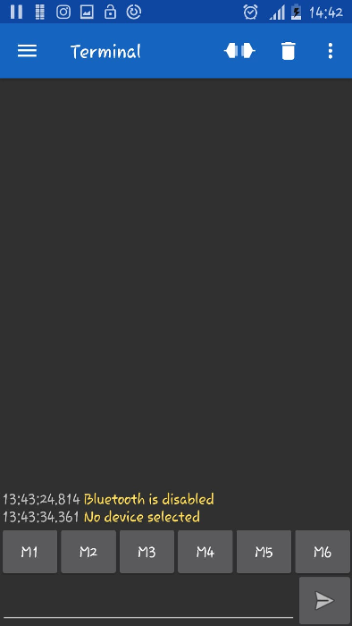
When you open the app this is the diplay you see.
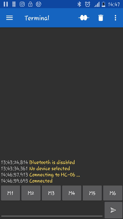
From the menu select the device to connect to in this case I selected the HC-06 then the bluetooth module connected as shown.
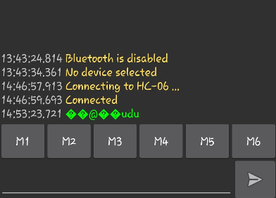
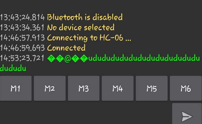
The hello board had the serial code for sending letter u and d when the button is pressed. To see it in action I just pressed the button and the data was sent to the phone application through the bluetooth module as shown.

A video demonstrating that;
Bluetooth
I used the bluetooth module for this assignment
It is a wireless technology standard for exchanging data over short distances (using short-wavelength UHF radio waves in the ISM band from 2.4 to 2.485 GHz) from fixed and mobile devices, and building personal area networks (PANs). Invented by telecom vendor Ericsson in 1994, it was originally conceived as a wireless alternative to RS-232 data cables.
Fabduino
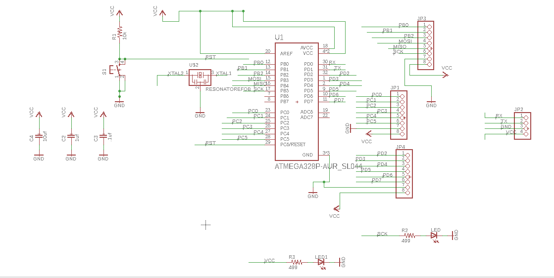
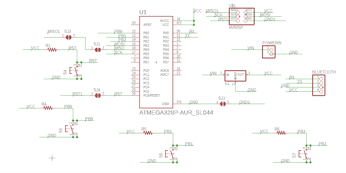
I made a fabduino board and included pin headers for the bluetooth module. I used eagle software to design it , as follows, used some components from the fab library and other from the eagle list.This is the schematic. I used the fabarduino example online and twisted it a bit by adding the bluetooth and changing a the microcontroller, connections and adding pin headers to help me add other components.

Control panel
I made a contol panel for my final project where I decided to put a bluetooth module for wireless communication with the other board . Since the panel has irectional press buttons I designed the board with different buttons for different directions that is the left and the right.
Challenges
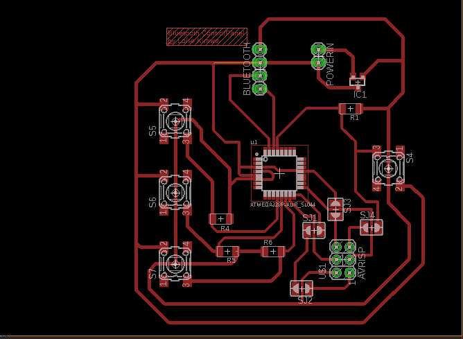
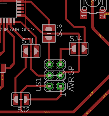
The AVRISP pins where overlapping each other and I had to pass some of the onnection lines between the pins, this posed to be a problem when milling so I decided to use jumpers to ease the connections beteen the lines and eliminate shot circuiting.
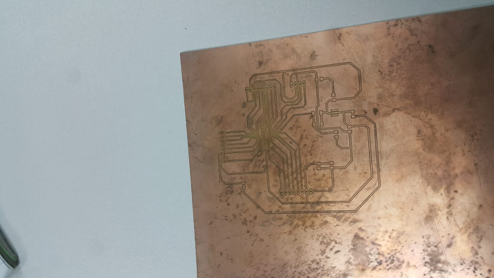
Milling
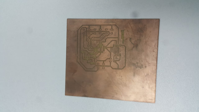
I milled the board using the bungard milling machine I follwed the instructions I had used for the other boards.At first I generated the garber files form eagle then imported the in the ISocam software to generete a plt file.I loaded the plt file in Routepro3000, then i set the correct settings for milling that is selecting the milling tool,the x and y axis, speeds.
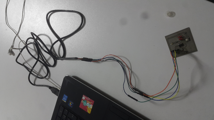
Due to my project changing this is where I reached on the bluetooth module communication due to time purpose I focused on the project which will be incooporating a wifi module to send data throughthe internet. I decide to do a Uart communication as shown below.
UARTs
The below descriptions i.e UART , bit bagging are citation from :Reference: Sparkfun
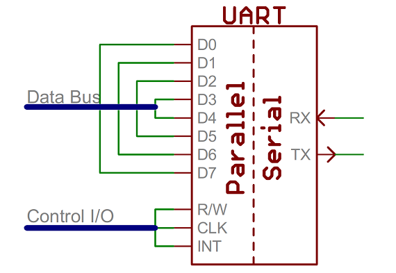
A universal asynchronous receiver/transmitter (UART) is a block of circuitry responsible for implementing serial communication. Essentially, the UART acts as an intermediary between parallel and serial interfaces. On one end of the UART is a bus of eight-or-so data lines (plus some control pins), on the other is the two serial wires - RX and TX.
As the R and T in the acronym dictate, UARTs are responsible for both sending and receiving serial data. On the transmit side, a UART must create the data packet - appending sync and parity bits - and send that packet out the TX line with precise timing (according to the set baud rate). On the receive end, the UART has to sample the RX line at rates according to the expected baud rate, pick out the sync bits, and spit out the data.
Bit banging
Bit banging is a technique for serial communications using software instead of dedicated hardware. Software directly sets and samples the state of pins on the microcontroller, and is responsible for all parameters of the signal: timing, levels, synchronization, etc. Its the concept of having the signals which go out of or come into a device be generated/sampled by software rather than hardware.
I used the hello World board, FTDI cable and python terminal.
The program modifications
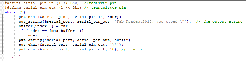
Programming the board
First I copied the program file and the makefile into one folder and used the following commands.
Make -f helloWorld.c.makeWhich gave the following :
avr-gcc -mmcu=attiny44 -Wall -Os -DF_CPU=20000000 -I./ -o helloWorld.out helloWorld.c avr-objcopy -O ihex helloWorld.out helloWorld.c.hex;\ avr-size --mcu=attiny44 --format=avr helloWorld.out AVR Memory Usage ---------------- Device: attiny44 Program: 756 bytes (18.5% Full) (.text + .data + .bootloader) Data: 60 bytes (23.4% Full) (.data + .bss + .noinit)
Then: Sudo make -f helloWorld.c program -usbtiny-fuses
Which gave the following feedback:
avr-objcopy -O ihex helloWorld.out helloWorld.c.hex;\ avr-size --mcu=attiny44 --format=avr helloWorld.out AVR Memory Usage ---------------- Device: attiny44 Program: 760 bytes (18.6% Full) (.text + .data + .bootloader) Data: 64 bytes (25.0% Full) (.data + .bss + .noinit) avrdude -p t44 -P usb -c usbtiny -U lfuse:w:0x5E:m avrdude: AVR device initialized and ready to accept instructions Reading | ################################################## | 100% 0.00s avrdude: Device signature = 0x1e9207 (probably t44) avrdude: reading input file "0x5E" avrdude: writing lfuse (1 bytes): Writing | ################################################## | 100% 0.01s avrdude: 1 bytes of lfuse written avrdude: verifying lfuse memory against 0x5E: avrdude: load data lfuse data from input file 0x5E: avrdude: input file 0x5E contains 1 bytes avrdude: reading on-chip lfuse data: Reading | ################################################## | 100% 0.00s avrdude: verifying ... avrdude: 1 bytes of lfuse verified avrdude: safemode: Fuses OK (E:FF, H:DF, L:5E) avrdude done. Thank you.
Followed Sudo make -f makefile program-usbtiny
Which gave the following feedback:
avr-objcopy -O ihex helloWorld.out helloWorld.c.hex;\ avr-size --mcu=attiny44 --format=avr helloWorld.out AVR Memory Usage ---------------- Device: attiny44 Program: 756 bytes (18.5% Full) (.text + .data + .bootloader) Data: 60 bytes (23.4% Full) (.data + .bss + .noinit) avrdude -p t44 -P usb -c usbtiny -U flash:w:helloWorld.c.hex avrdude: AVR device initialized and ready to accept instructions Reading | ################################################## | 100% 0.00s avrdude: Device signature = 0x1e9207 (probably t44) avrdude: NOTE: "flash" memory has been specified, an erase cycle will be performed To disable this feature, specify the -D option. avrdude: erasing chip avrdude: reading input file "helloWorld.c.hex" avrdude: input file helloWorld.c.hex auto detected as Intel Hex avrdude: writing flash (756 bytes): Writing | ################################################## | 100% 1.20s avrdude: 756 bytes of flash written avrdude: verifying flash memory against helloWorld.c.hex: avrdude: load data flash data from input file helloWorld.c.hex: avrdude: input file helloWorld.c.hex auto detected as Intel Hex avrdude: input file helloWorld.c.hex contains 756 bytes avrdude: reading on-chip flash data: Reading | ################################################## | 100% 1.48s avrdude: verifying ... avrdude: 756 bytes of flash verified avrdude: safemode: Fuses OK (E:FF, H:DF, L:5E) avrdude done. Thank you.
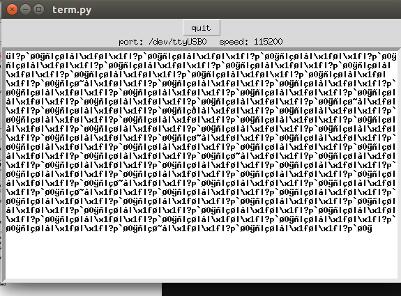
I then left the directory and started the python terminal using the command.
Python term.py /dev/ttyUSBO 115200The terminal then began and i connected the FTDI cable to the computer. The first results were incoherrent as seen below so i began troubleshooting to find the error points. I then realised i needed to connect the transmit pin to the receive portal of the FTDI.
The second results were as seen;

It finally worked and below is a video.