Week 2
Computer-aided design
Assignment
• Model (raster,vector, 2d, 3d, render, animate, simulate) a possible final project.
2D design process
I practiced on freecad at first where i made several shapes. Am a newbie soo I tried to get acquited to with several other softwares e.g. Inventor, Inkscape and Onshape. There where a few challenges with getting used to how they work but finally I managed to get the logic behind it.
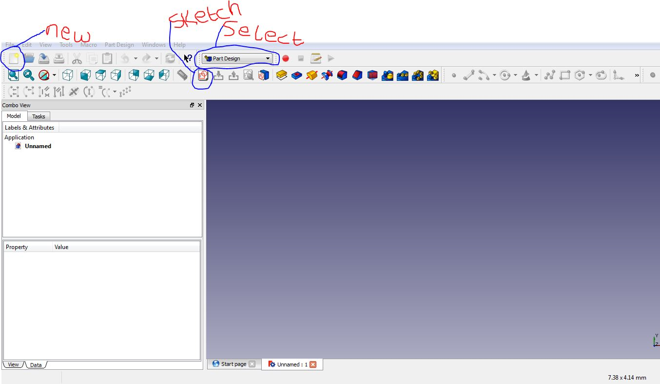
Freecad
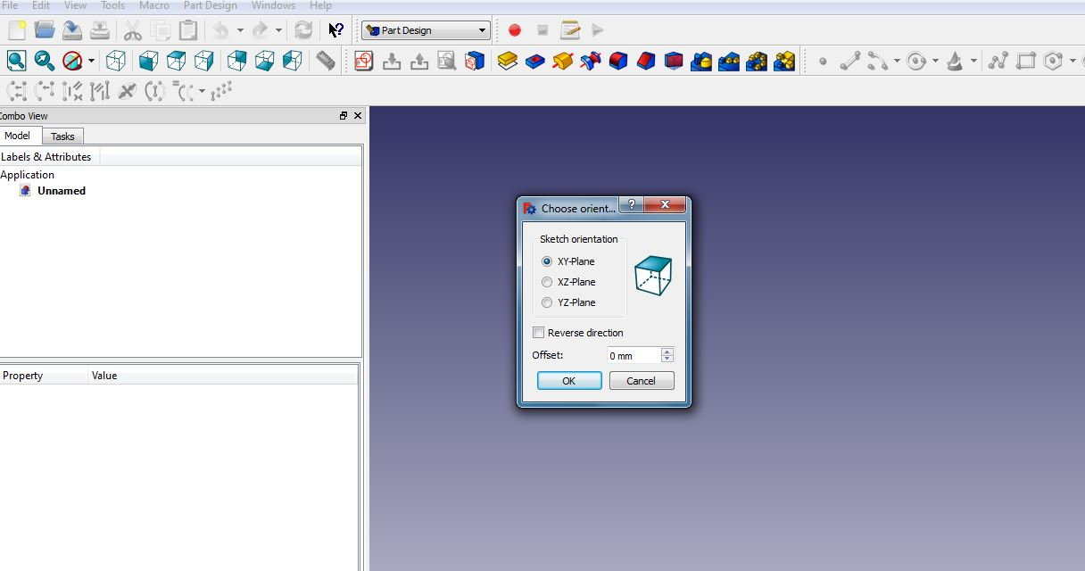
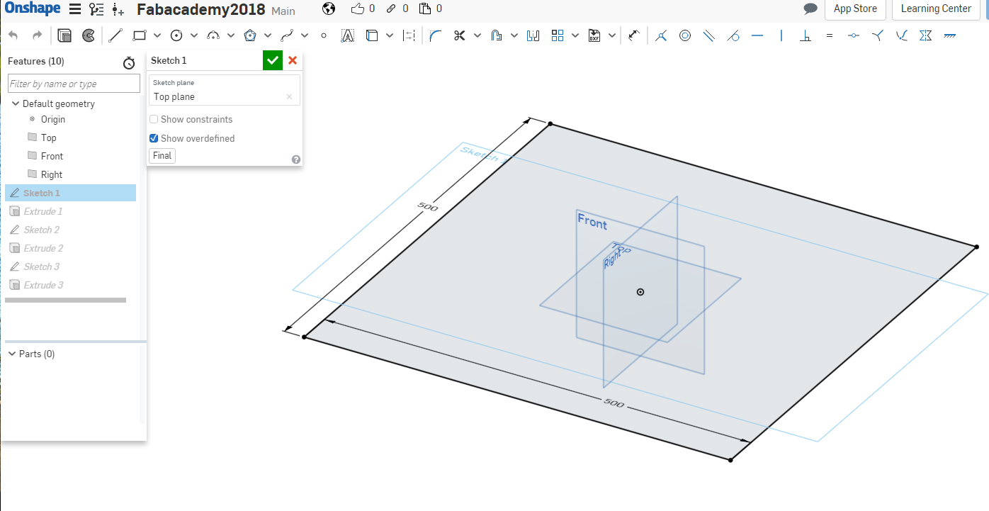
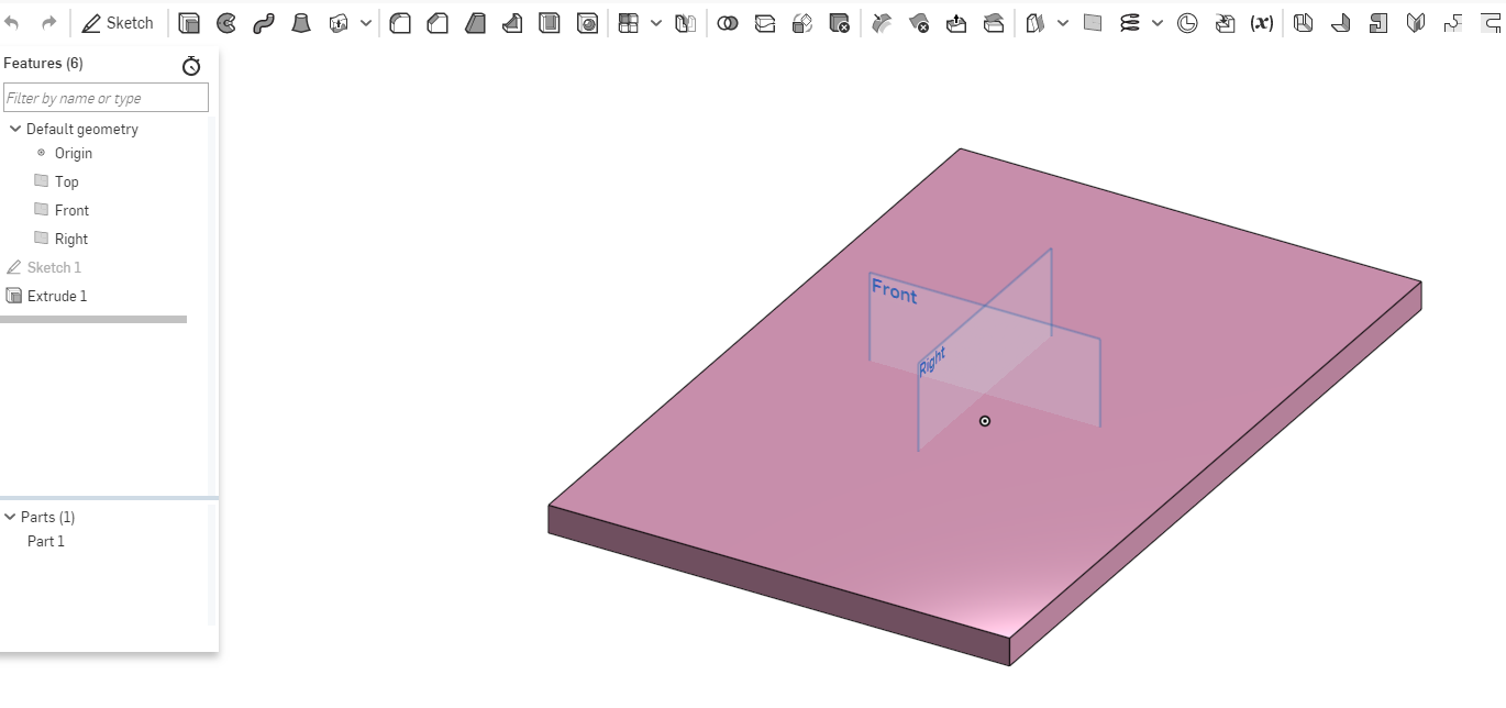
First I downloaded the exe file from there website and installed it on windows. This is the image I made after several try and errors. I did a simple 2d design show casing the parametric concept. I created a new file then choose part design from the drop down. I chose sketch button to start a sketch. It prompts a window to choose a plane as shown below.
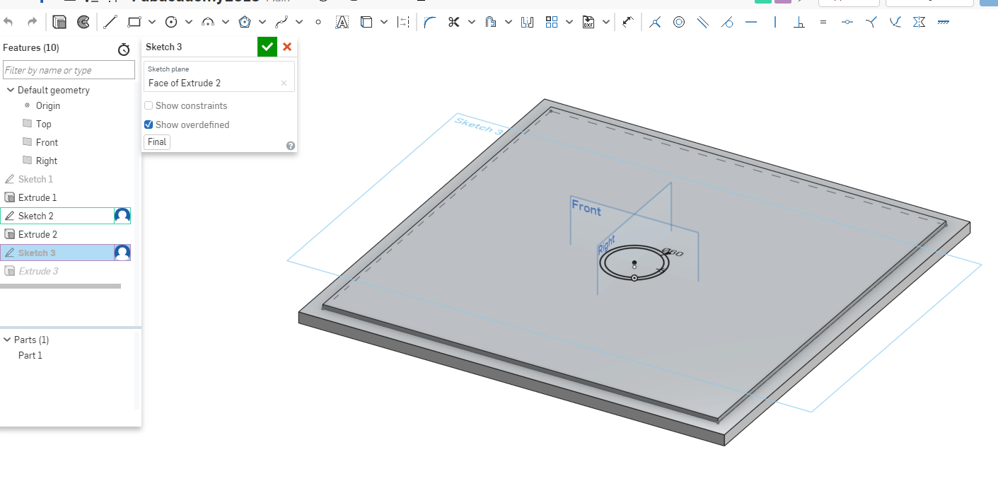
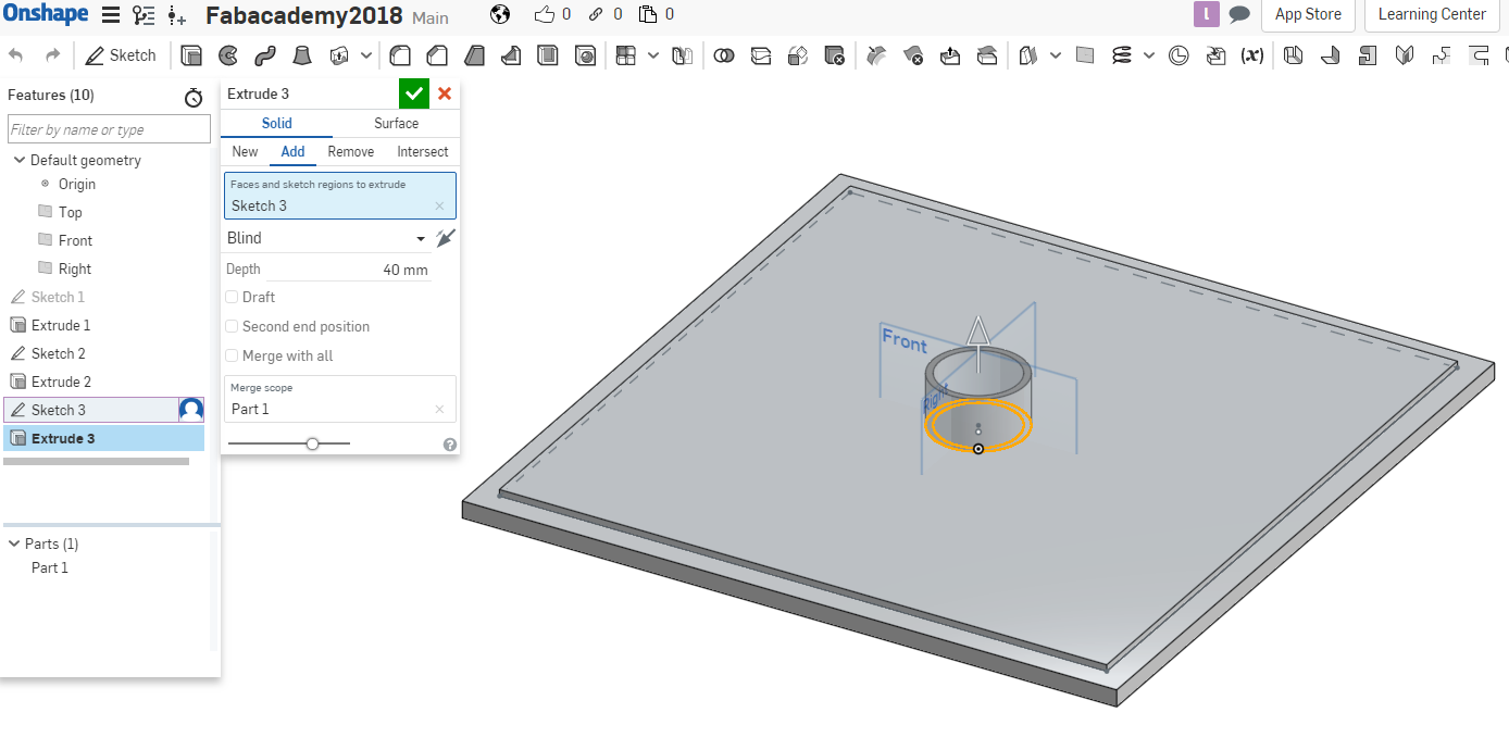
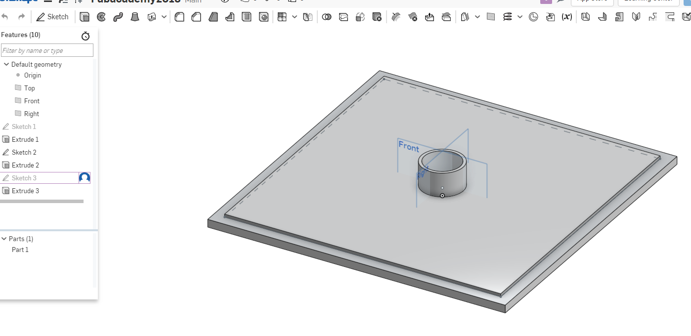
2D and 3D process for Current Project
Since in this project I will be automating the watering system part of the project this are the parts involved in the whole process as shown. Some of the parts will be 3D printed while others will be lasercut and machines using the plasma cnc machine. Am using Inventor software to design the parts.
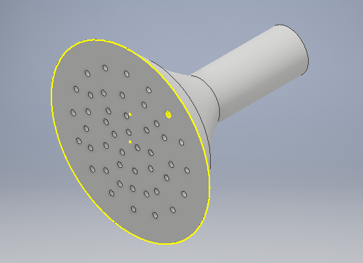
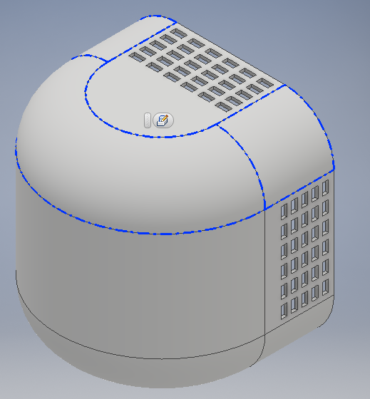
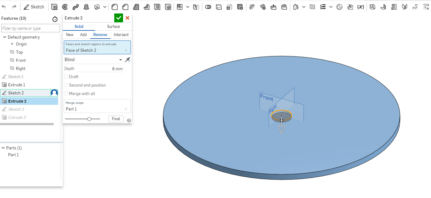
Sprinkler
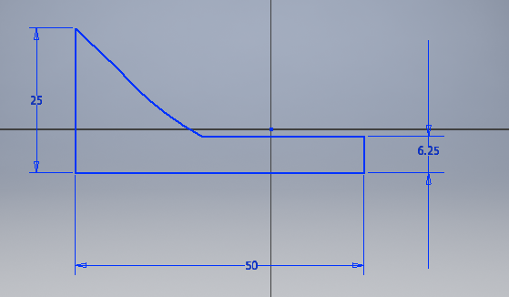
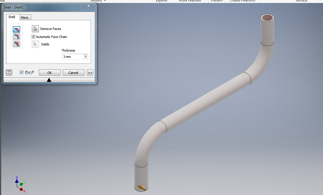
Drew a sketch using the hand line tool and curve tool gave it some measurements, then using the shell tool to remove the material on the inner part od the shape. The revolve tool came in handy as it revolved the shape I had created all around.
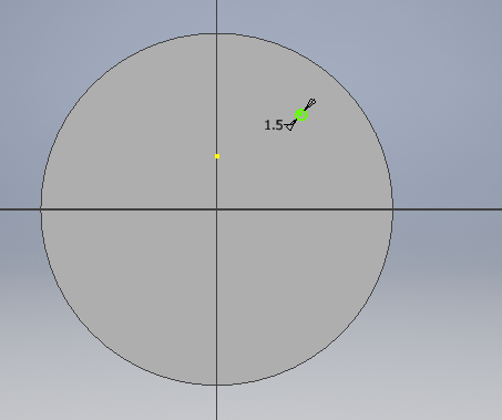
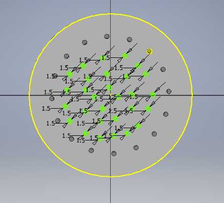
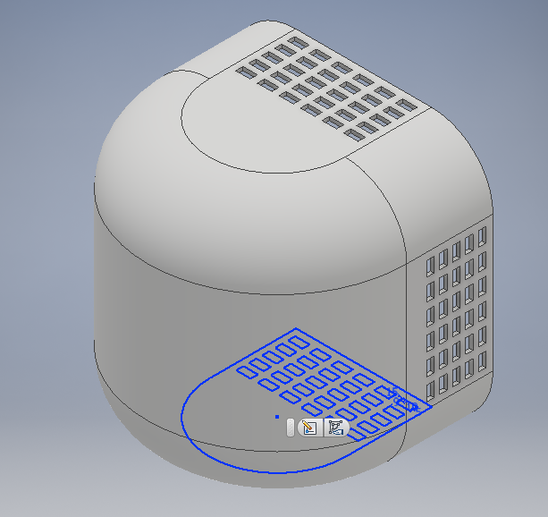
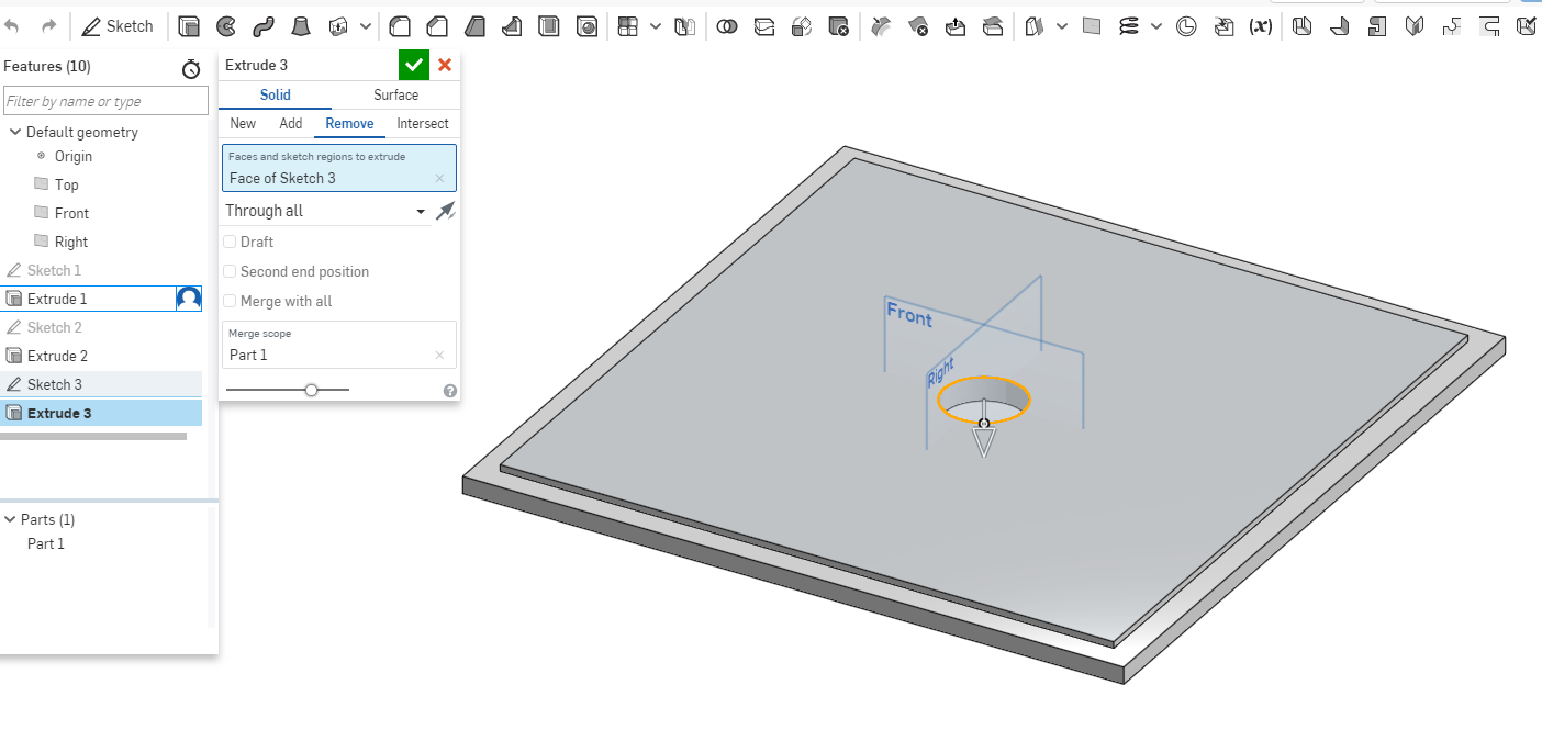
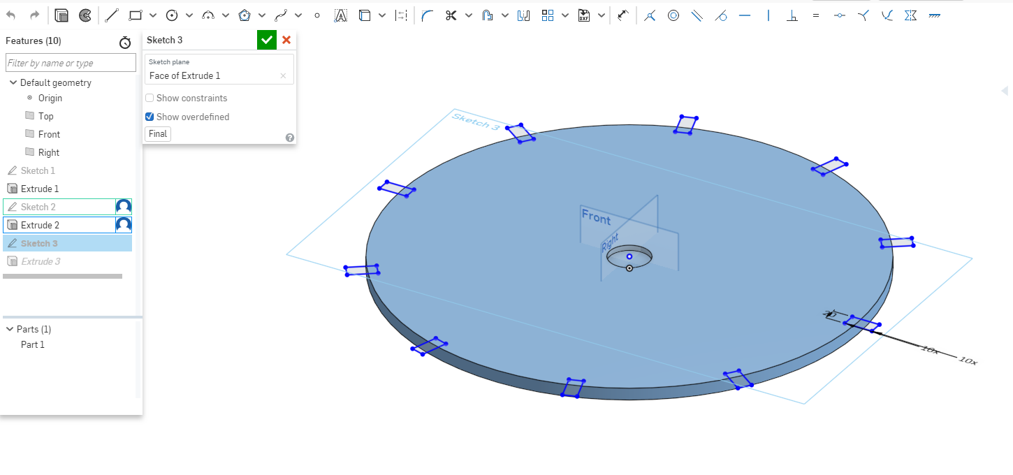
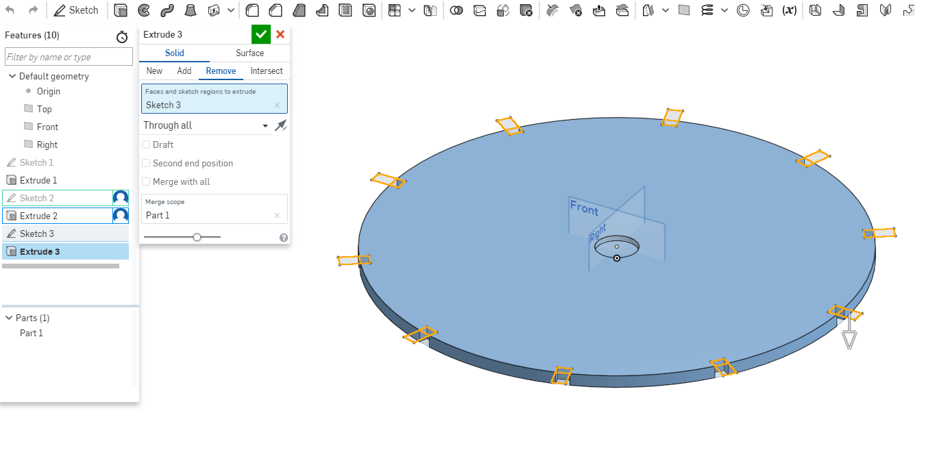
Then created another sketch for the on the surface of the sprikler as shown. I drew a circle and gave it dimension then I used the circular pattern tool to create a series of the circles as shown. Then extruded them.
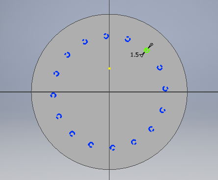
For the inner cicles I gave drew just one circle then copied it all around. After that I extruded it.
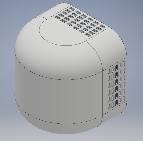
The final sketch as shown.
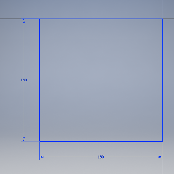
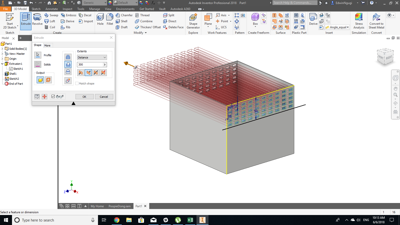
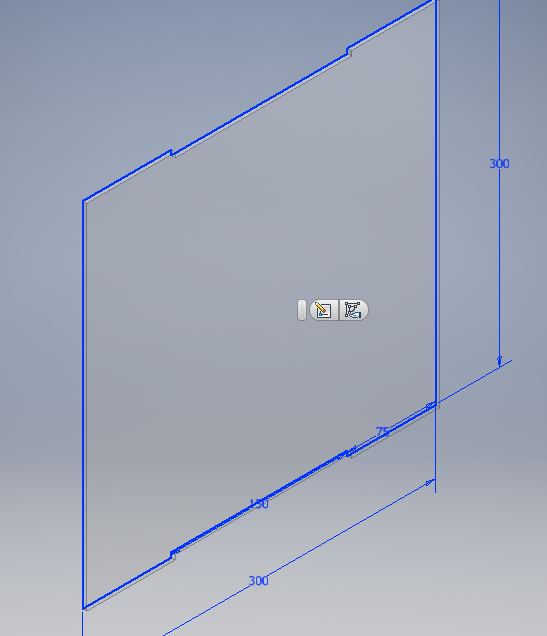
Plant Encasing
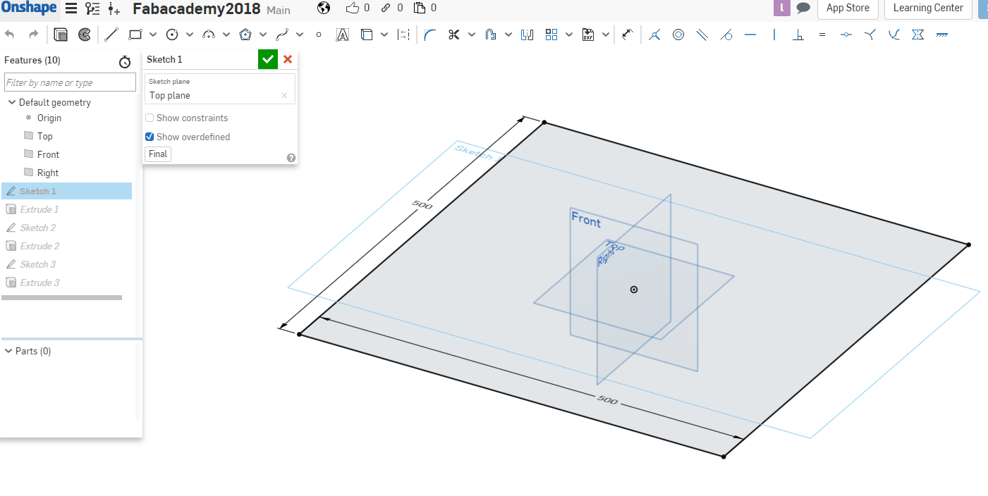
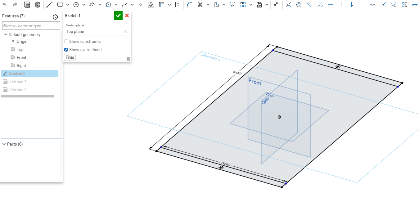
Started with a rectangle then I gave it dimensions as shown.
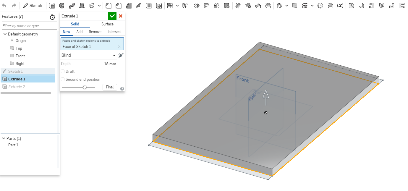
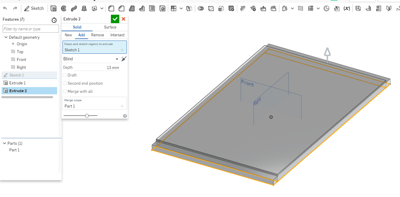
The extruded the shape. Did another sketch and drew and extruded.
Used the fillet tool and shell tool to shape the design.
Redid the rectangle extrusion.
Final look.
Main Container
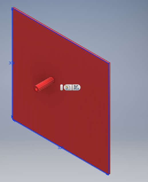
I did three parts for the container where for the two sides I incoporated a pressfit fitting.
Length
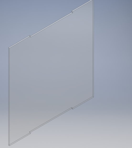
Width
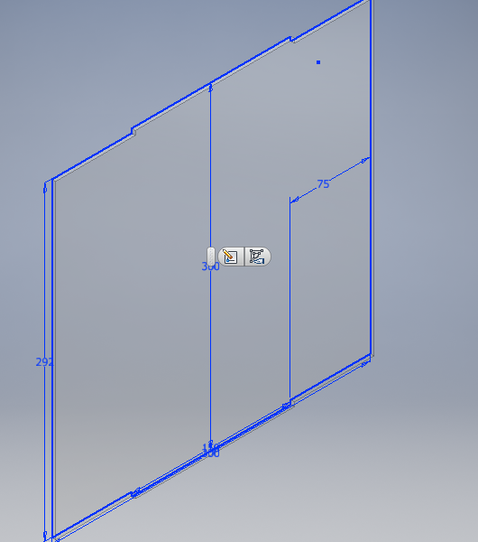
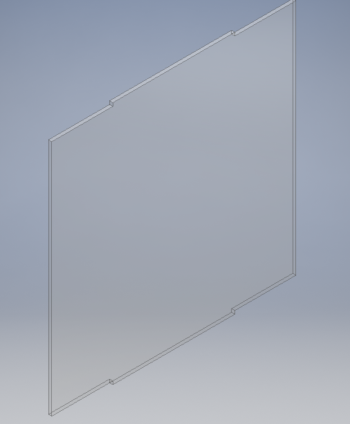
Base
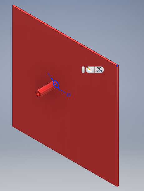
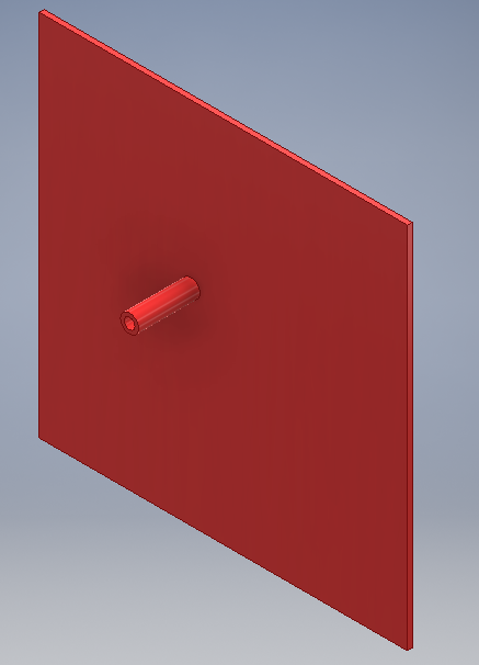
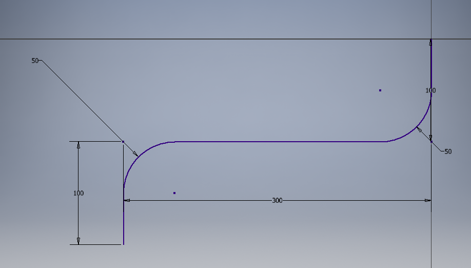
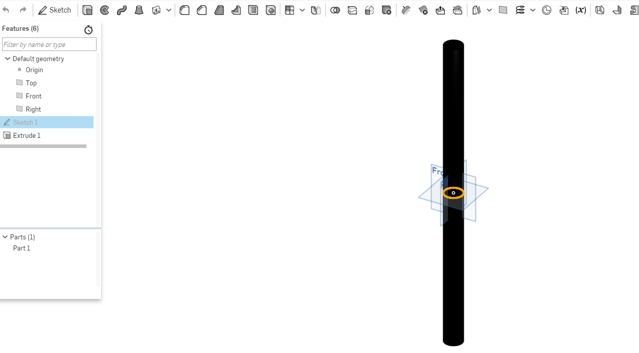
Pipe
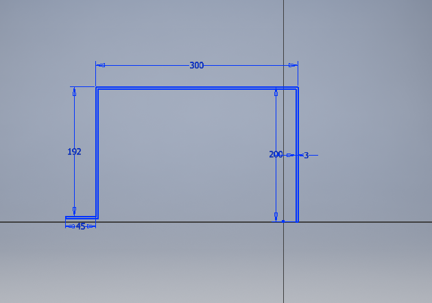
Drew a curved line using the line curve tool and gave it measurements as shown.Use dthe sweep tool to form the shape of the pipe across the curved line.
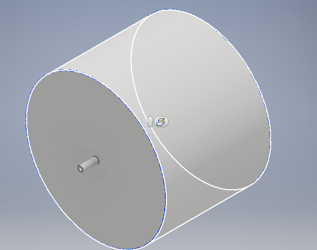
Water tabk container
Did a sketch then I revolved it using the revolve tool. fillet the design
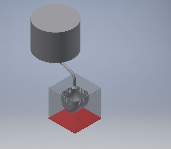
Assembly of the project
To assemble I created a new asembly in inventor it allows you to imports the parts that you would like to assemble. Thus I imported all the parts the assembled them using the constraint tool that allows you to mate the parts depending on how the interconnect.
2D and 3D process for Previous Project
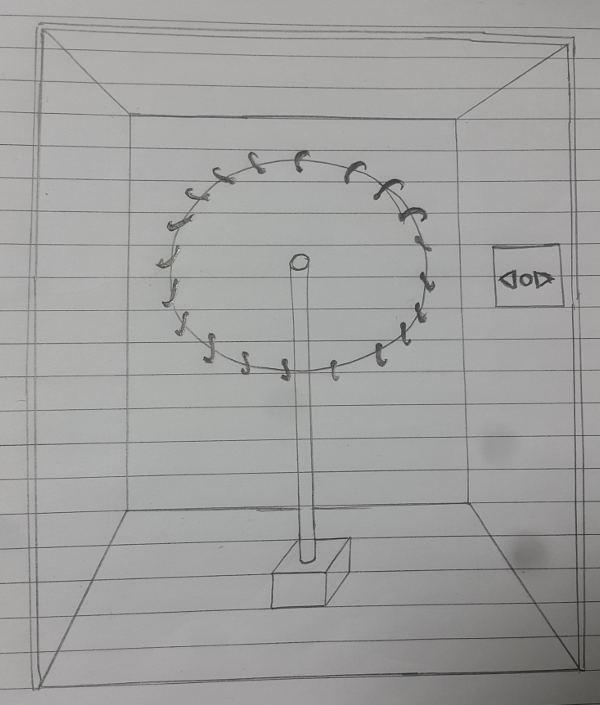
My project I started by doing the sketch design in a paper as shown. As shown in week 0 for principles and practices i brokedown the project.
Electronic box design
Bottom Part
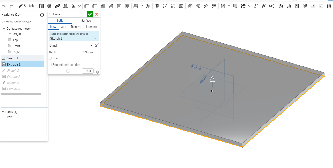
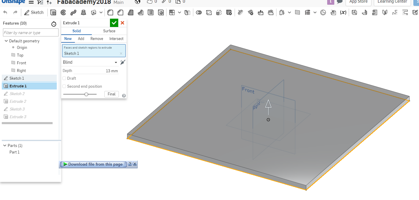
Since the box is rectangular shaped, I started with a rectangle shape on the side plane. Then extrudeeed it a few mm.
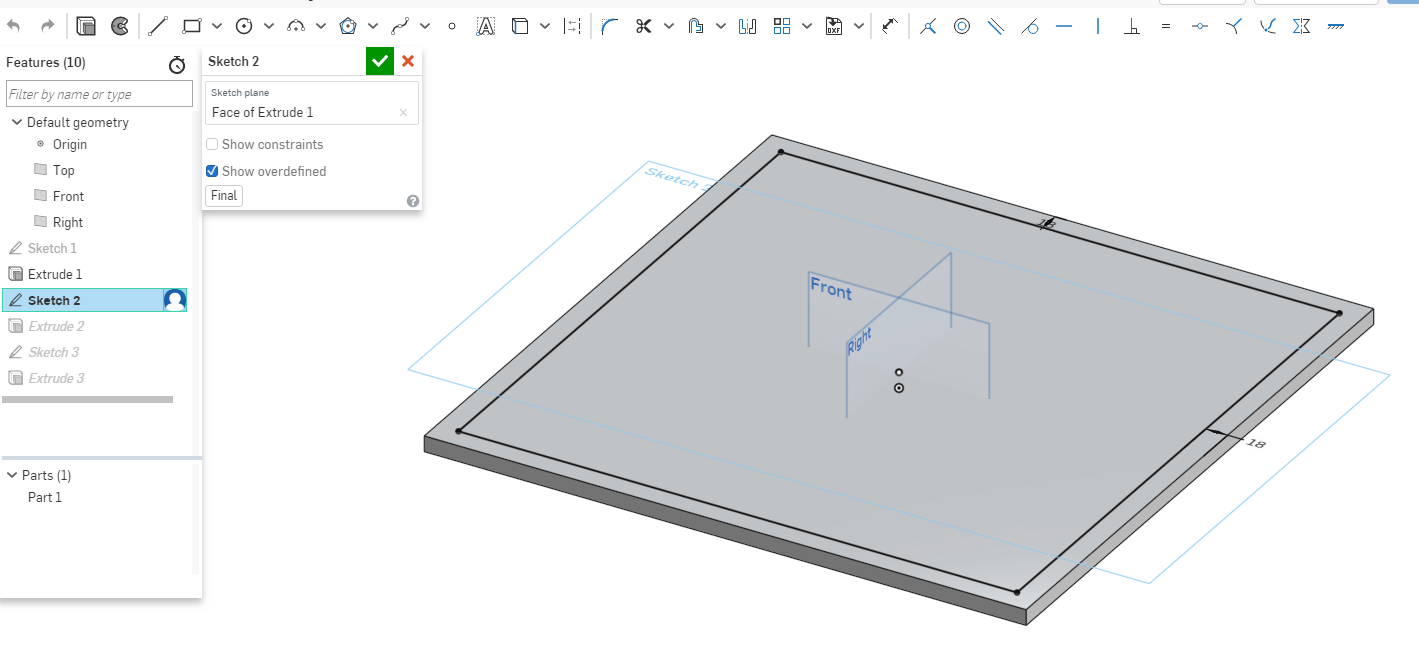
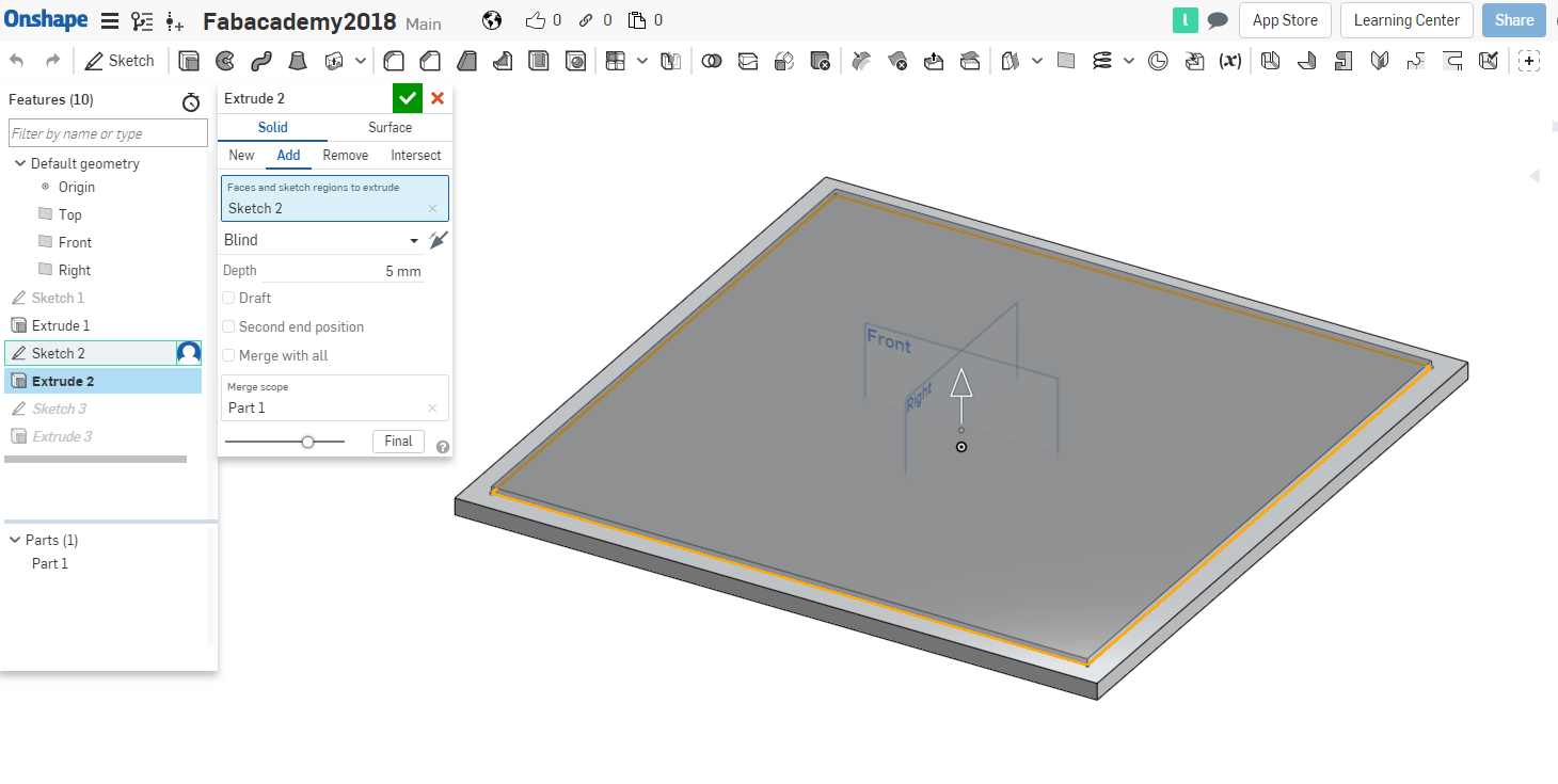
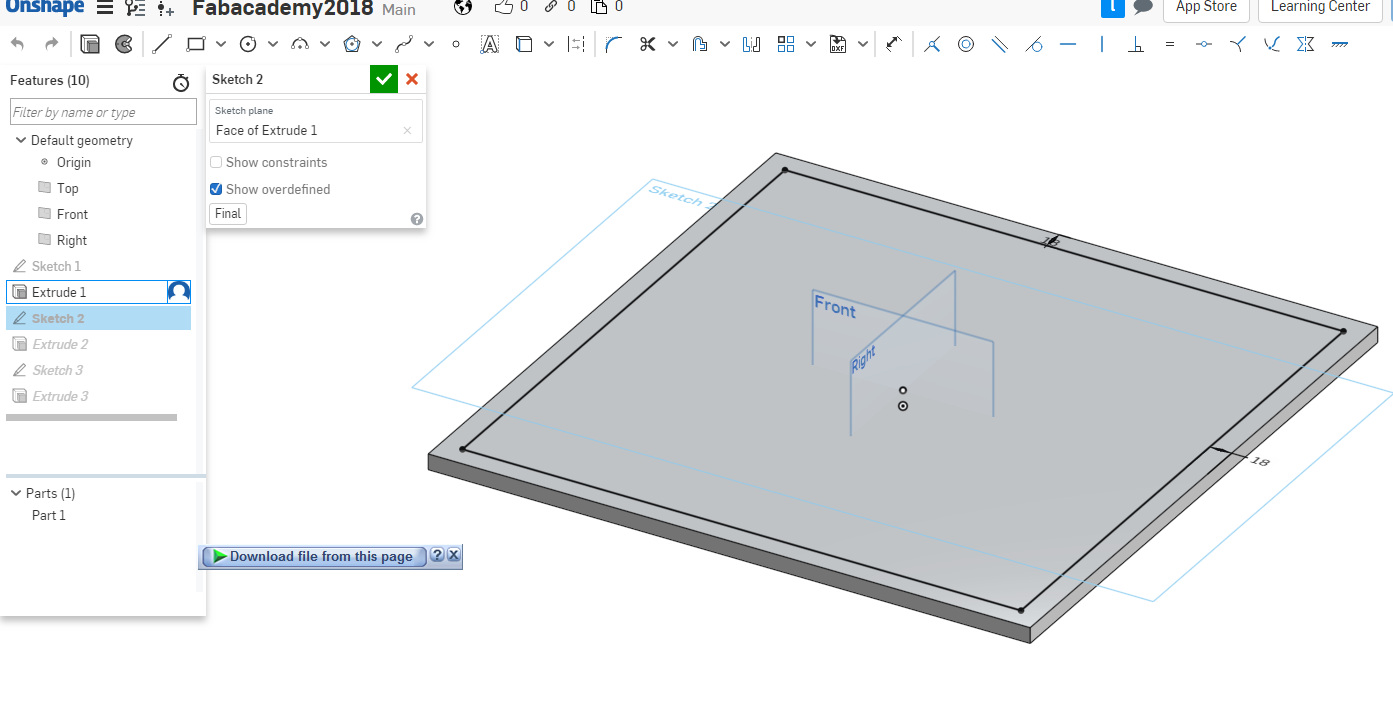
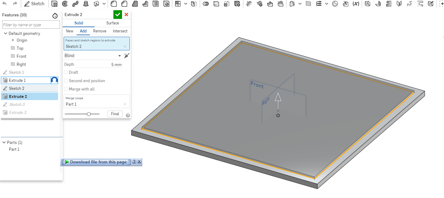
Wanted it to be able to fit in with the other shapes so I did another sketch on top of the current sketch and extrude it. .
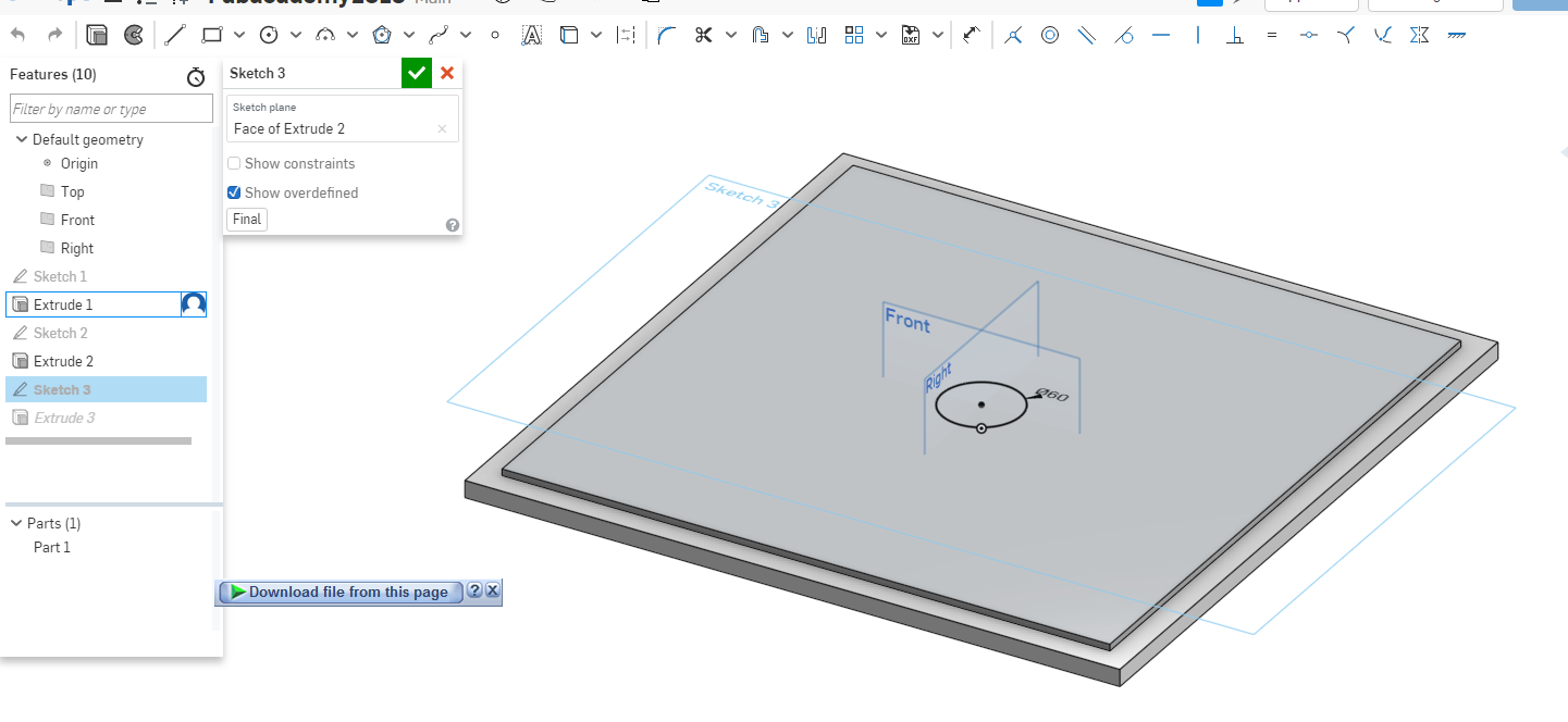
The box at will be at the bottom and will hold the pipe.I did a sketch on the current sketch and drew circular shape then extruded it a few mm.
Top Part
This was similar to the bottom part design where I did a rectangular shape with the same measurements as the bottom part then extruded it.
I did another sketch on top of the current sketch and extrude it.
The top part i did a circular shape where the pipe will go through then removed the material to make a hole.
Sides part
I did a similar step by using a rectangle and giving it the right measurements then extruded the sketch.
Front part
This was a simple sketch then i extruded it.
Rotating part
This part has several parts involved which will be the hooks, hangers and pipe that will be holding it in place.The revolving part I did a circle then gave it dimension. I extrude it a few mm as shown.
For the pipe section I did a Circle with the same measurements as the rest of the parts the remove a small part.
For the hooks part i did rectangular insertions then removed the part from the design to form those insertions.
Pipe
I did a circular shape then extrude.
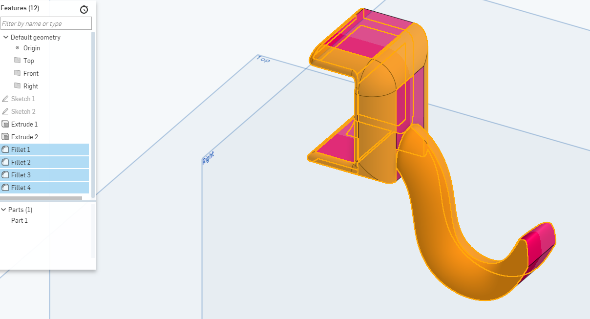
Hooks
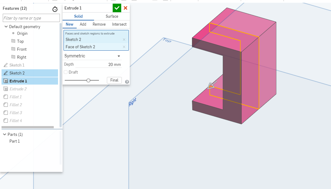
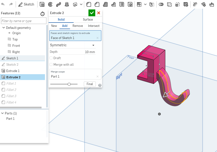
I did two sketch for the two parts of the hook using a free tool and a line tool to draw the design.
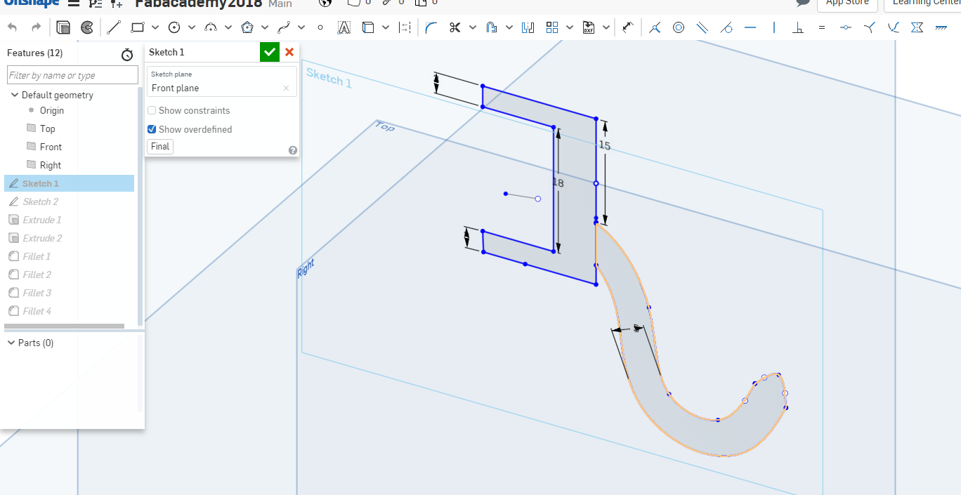
Then extruded the two parts differently.
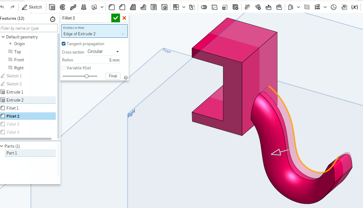
Using the fillent tool to smoothen the surface of the hooks.
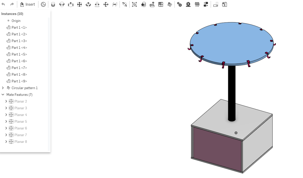
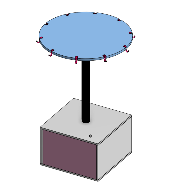
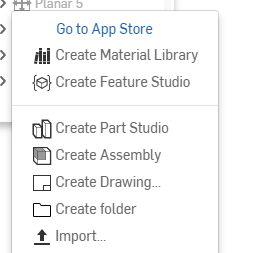
Assembly
To be able to assemble different parts of the different designs, you start by creating a new assemmbly as shown below.
The insert brings a pop up window that shows you the different designs you have in your directory.To select a design you just click and drag it to the position on the sketch.
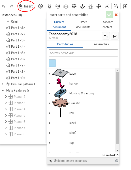
I inserted the parts I needed for assembly as shown below one by one while connecting them.
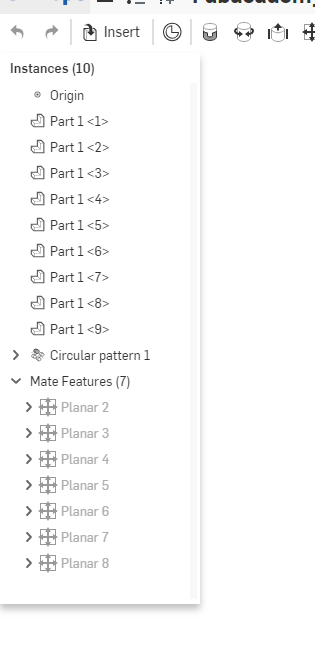
I used the planar mate tool to connect the different parts together.
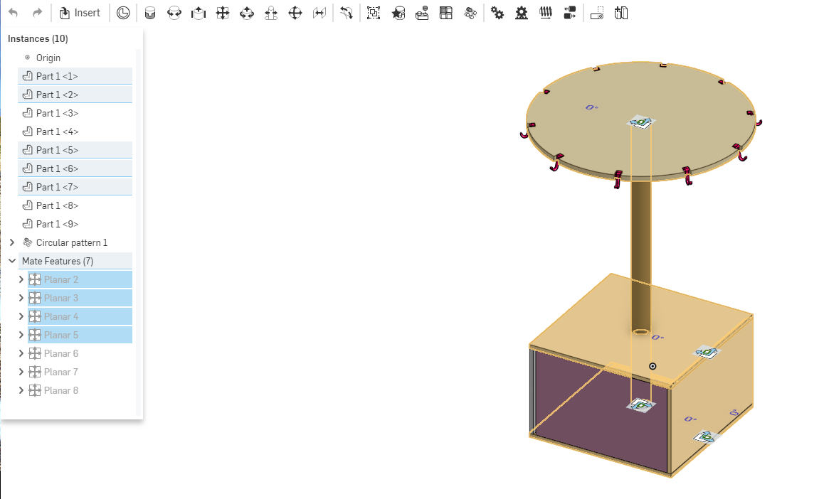
The final image after assembly.