Week 7
Computer-controlled machining
Assignment
Group
• test runout, alignment, speeds, feeds, and toolpaths for your machine.
Individual• make something big
Tests
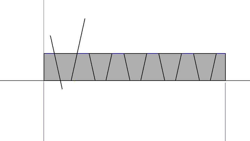
Runout
Runout " is an inaccuracy of rotating mechanical systems, specifically that the tool or shaft does not rotate exactly in line with the main axis.For example; when drilling, run-out will result in a larger hole than the drill's nominal diameter due to the drill being rotated eccentrically (off axis instead of in line). In the case of bearings, run-out will cause vibration of the machine and increased loads on the bearings"Reference:wikipedia
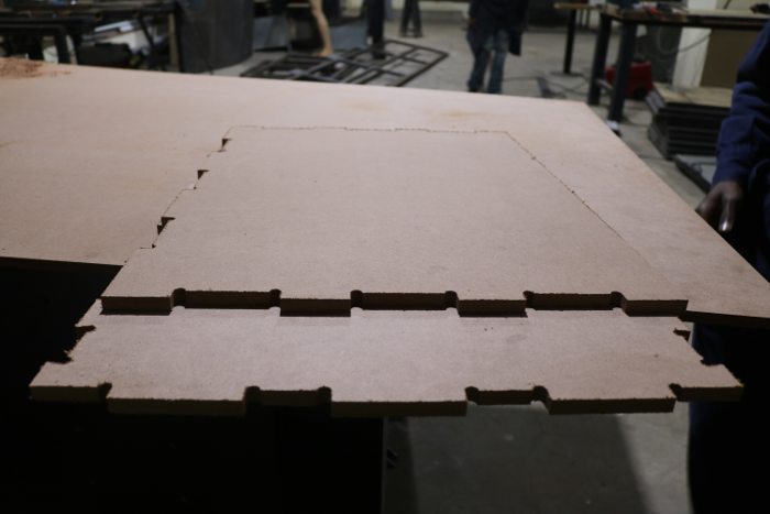
To run the tests the I divided it into 3 stages; Design process, CAM process and Machine Process. I first began with a small piece of my design.
To do the runout test this is how my initial design looked like with edged corners.
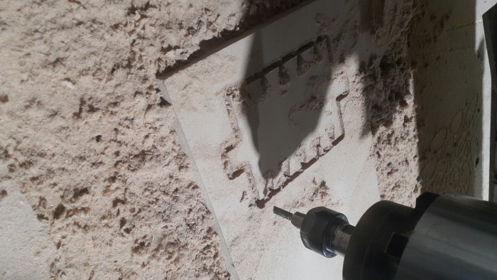
After machining the workpiece was curved on inner edges due to the size of the tool used .
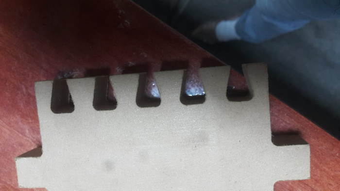
To compensate for the runout, the design incorporated dogbone technique which made the pressfit mechanism work.
Feeds and speeds
Feedrate: The distance the spindle moves relative to the time it takes to move along the workpiece
• Units are distance / time, usually in/min or mm/min.Spindle Speed: The rotational speed of the spindle.
• Units are revolutions per minute or RPM.Make something big
CNC Machine
Drill
Drilling is a cutting process that uses a drill bit to cut a hole of circular cross-section in solid materials. The drill bit is usually a rotary cutting tool, often multi-point. The bit is pressed against the work-piece and rotated at rates from hundreds to thousands of revolutions per minute. This forces the cutting edge against the work-piece, cutting off chips (swarf) from the hole as it is drilled.
Pocket milling allows the machinist to use an end mill type cutting tool and machine away large amounts of material in a “Roughing” cycle prior to finishing the part. This saves time and efficiently maximizes the amount of material removal. There are different styles of pocket toolpath that include traditional lace or zig-zag (back and forth), concentric or offset In/Out and high speed cutting paths.
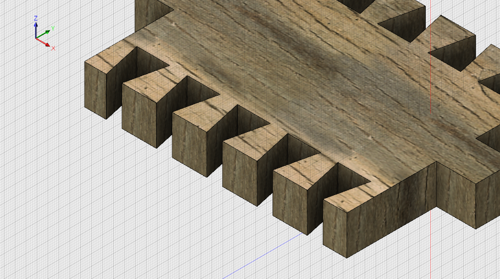
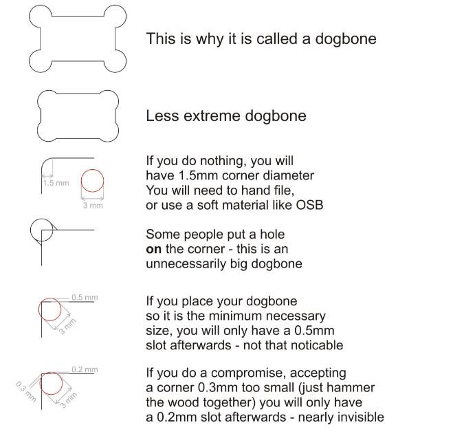
Dogbones
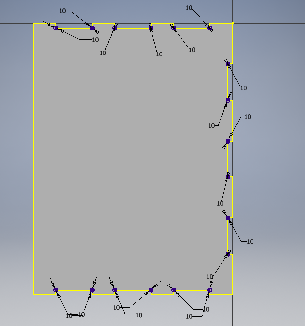
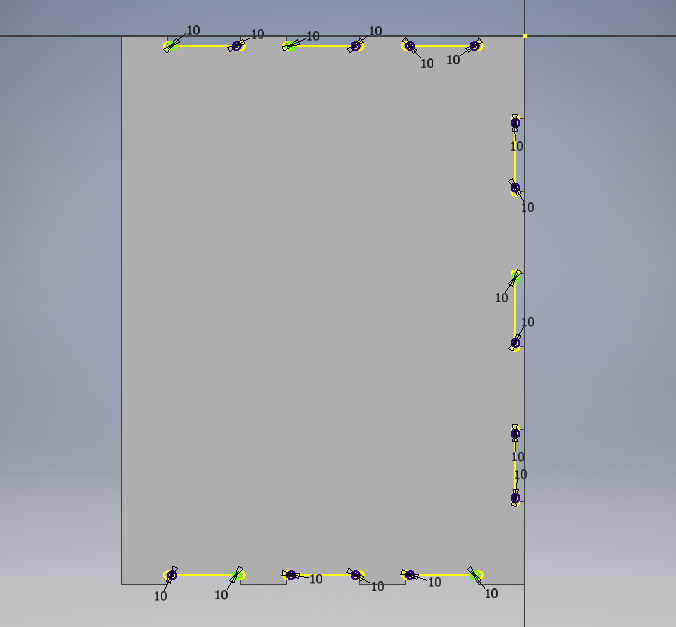
When cutting materials with the CNC, a known problem is that while the CNC can make a perfect outer corner, the inner corners can never be more sharp than the diameter of the cutting tool. So if you are e.g. using a 6mm mill, all the inside corners will not be perfect right angles, but will instead have an inside diameter of 3 mm (half the cutting tool's diameter) Sometimes these small rounded corners don't matter, but they are almost always an issue with joints - where often another piece of plywood, which by nature is square, must fit precisely in a hole or slot. If the hole or slot has very rounded corners, the mating piece just isn't going to fit in.
Nesting
In manufacturing industry, Nesting refers to the process of laying out cutting patterns to minimize the raw material waste. Examples include manufacturing parts from flat raw material such as sheet metal, wood etc.
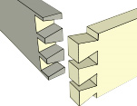
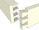
Dovetail joints
A dovetail joint or simply dovetail is a joinery technique most commonly used in woodworking joinery (carpentry) including furniture, cabinets, log buildings and traditional timber framing. Noted for its resistance to being pulled apart (tensile strength), the dovetail joint is commonly used to join the sides of a drawer to the front. A series of 'pins' cut to extend from the end of one board interlock with a series of 'tails' cut into the end of another board. The pins and tails have a trapezoidal shape. Once glued, a wooden dovetail joint requires no mechanical fastener.Reference:wikipedia
The following are the different types of dovetail joints:
Through dovetail
Half-blind dovetail
Secret mitred dovetail

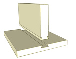
Sliding dovetail
Design process
First Design
I will be designing a wardobe from the previous project.In this case I will be using the through dovetails to interconnect the sides of the wardrobe. I used Inventor software to design the 2D and 3D parts of the wardrobe. As shown;
Second Design
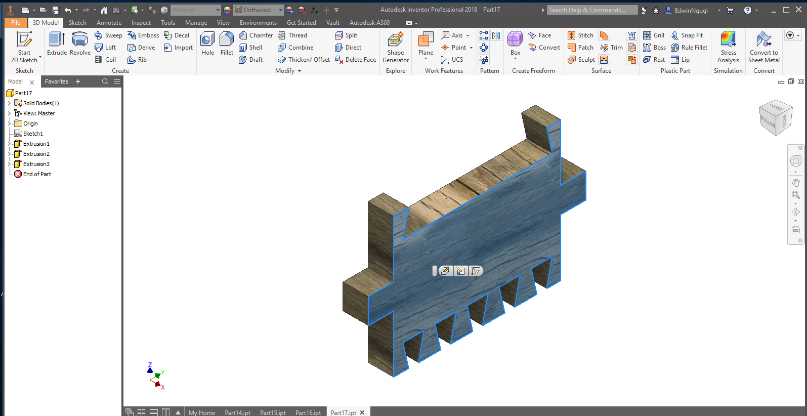
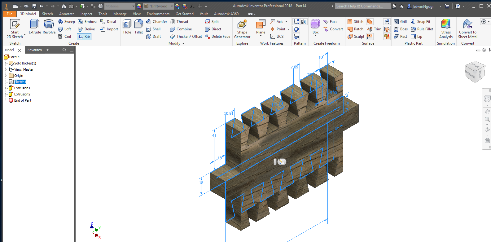
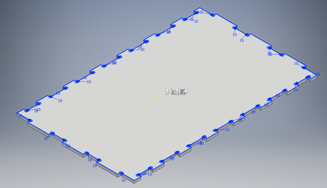
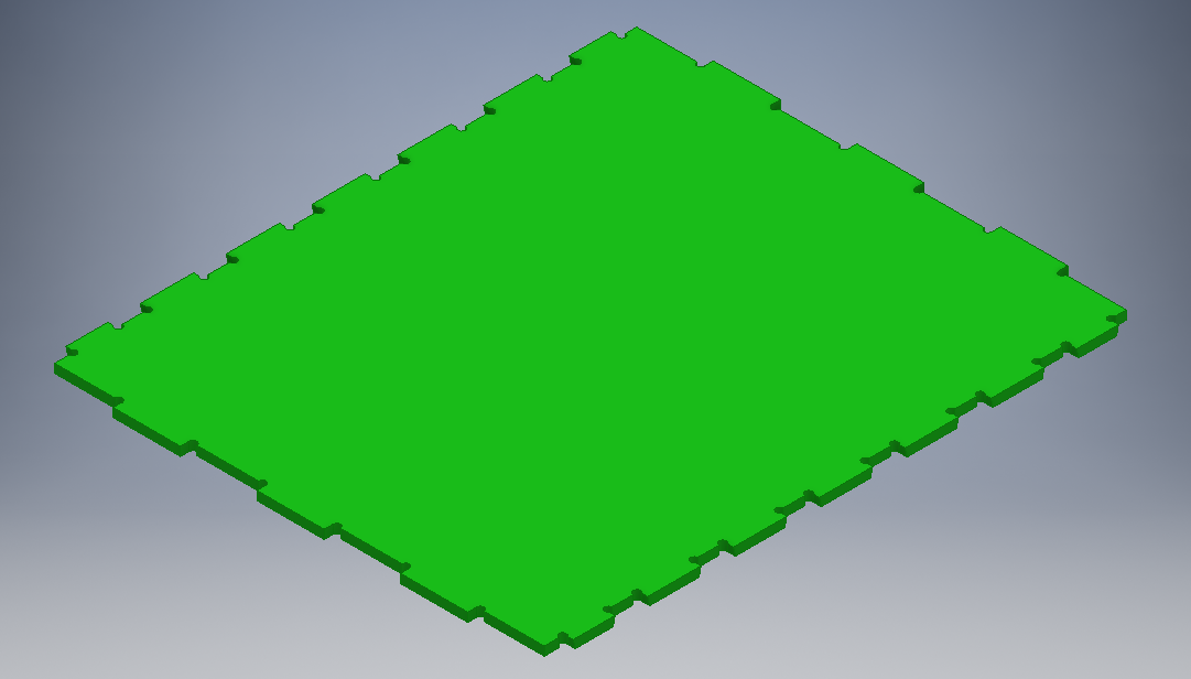
For this design I used the dogbones to make the joints fit together.
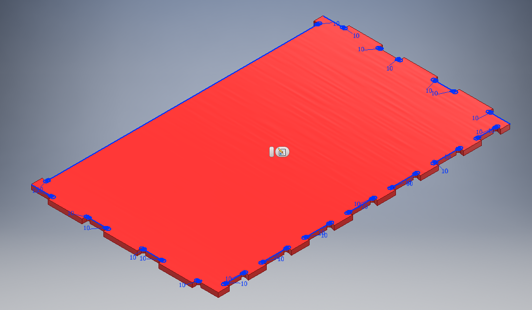
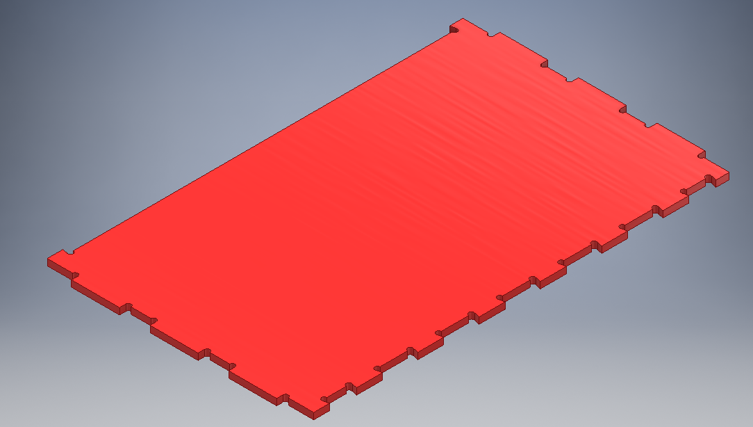
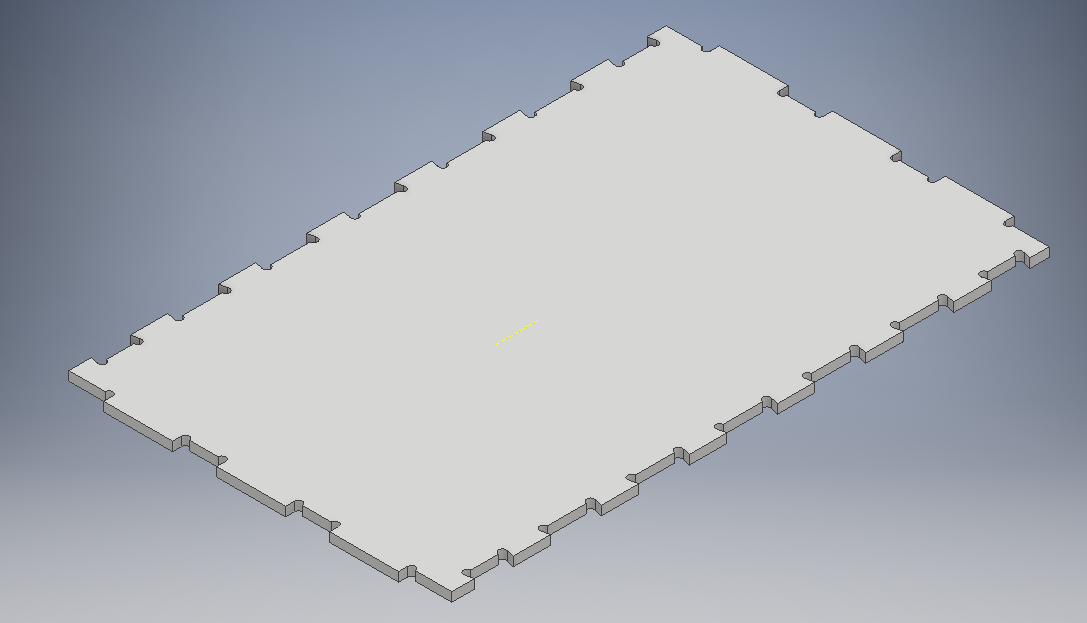
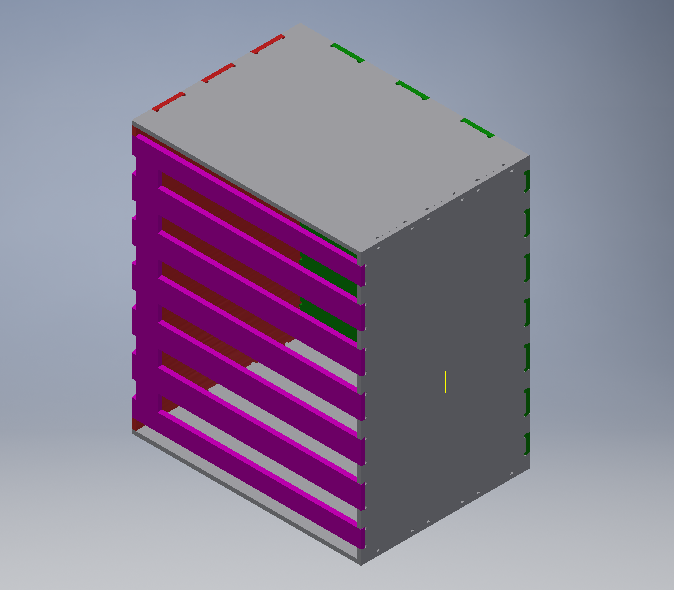
Top and bottom parts
To make it a perfect pressfit I added more design part added the insertions holes and extruded them as shwon.

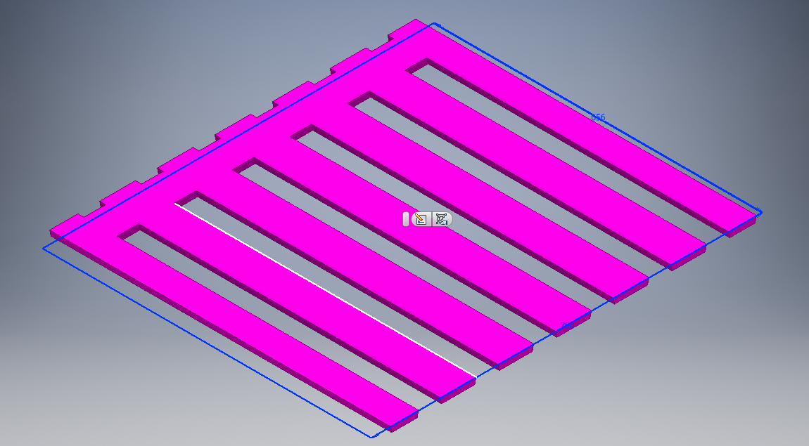
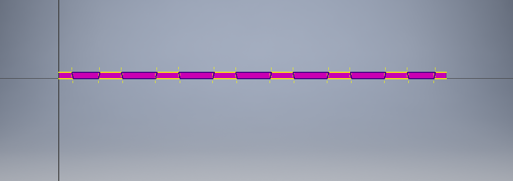
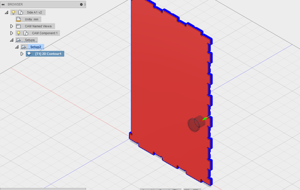
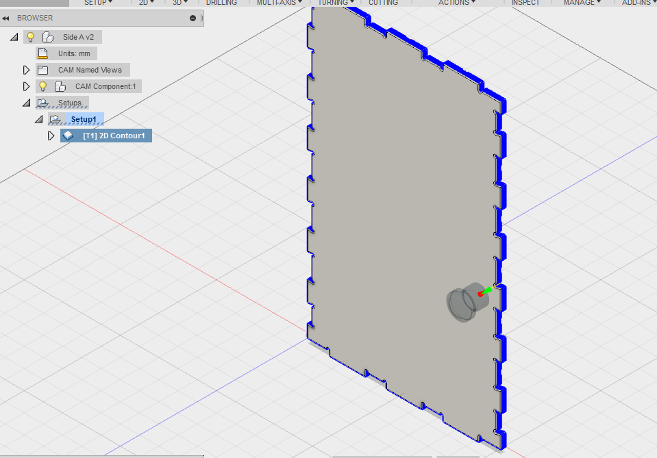
Side parts
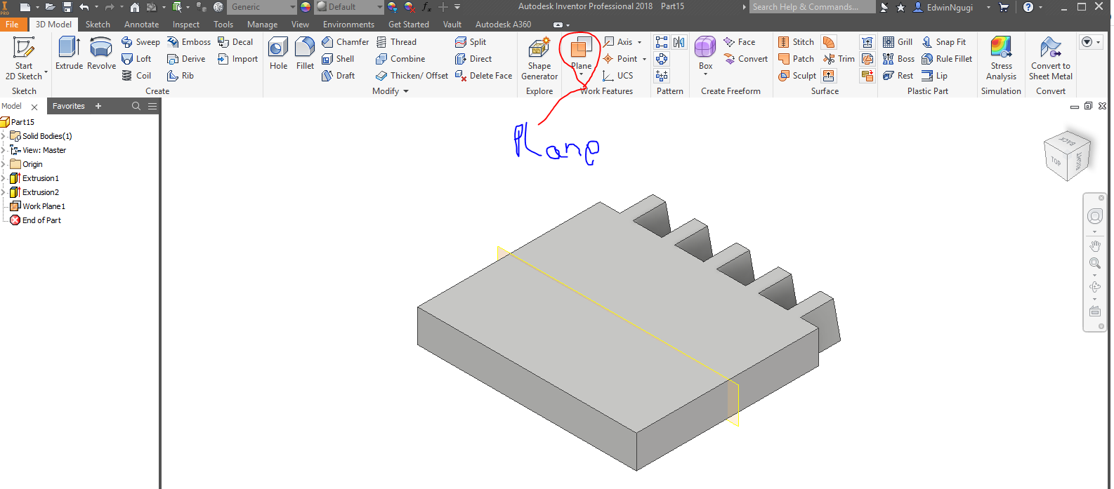
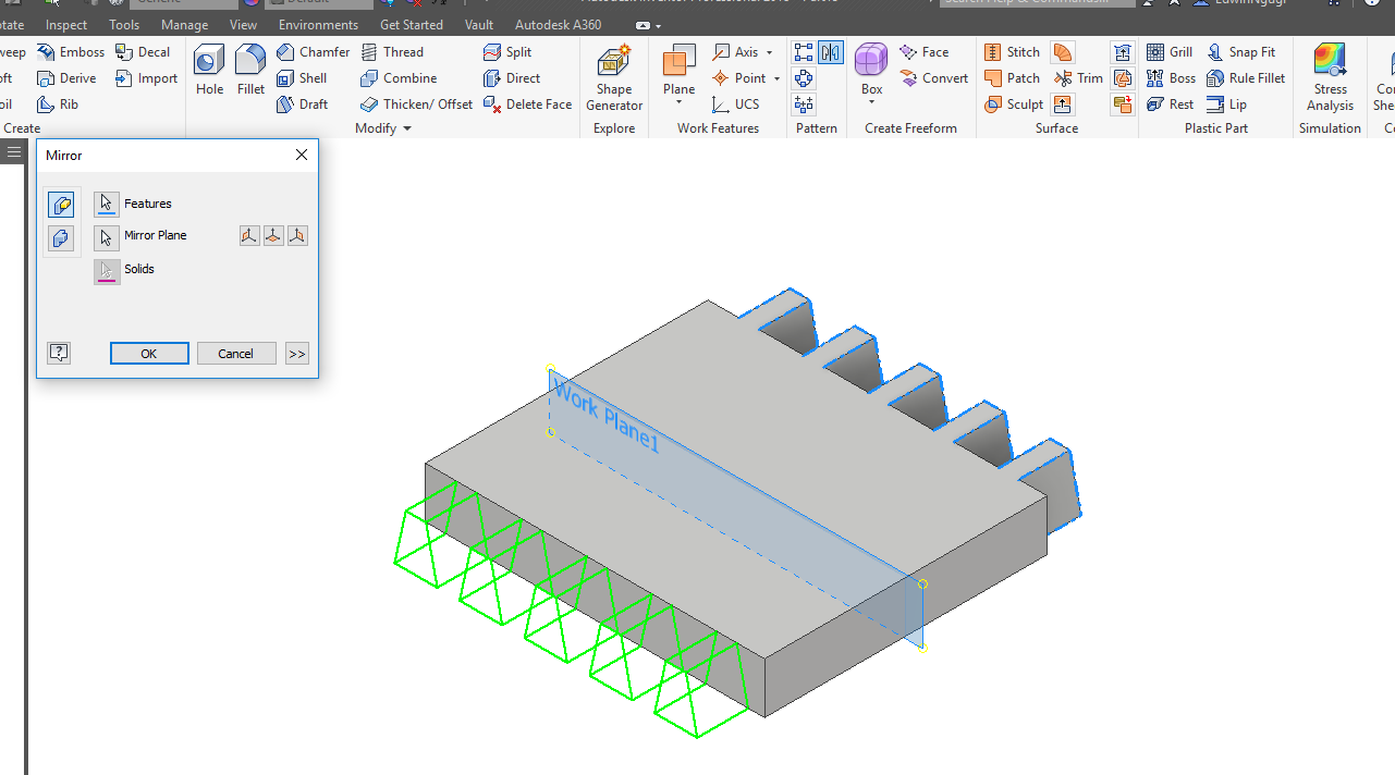
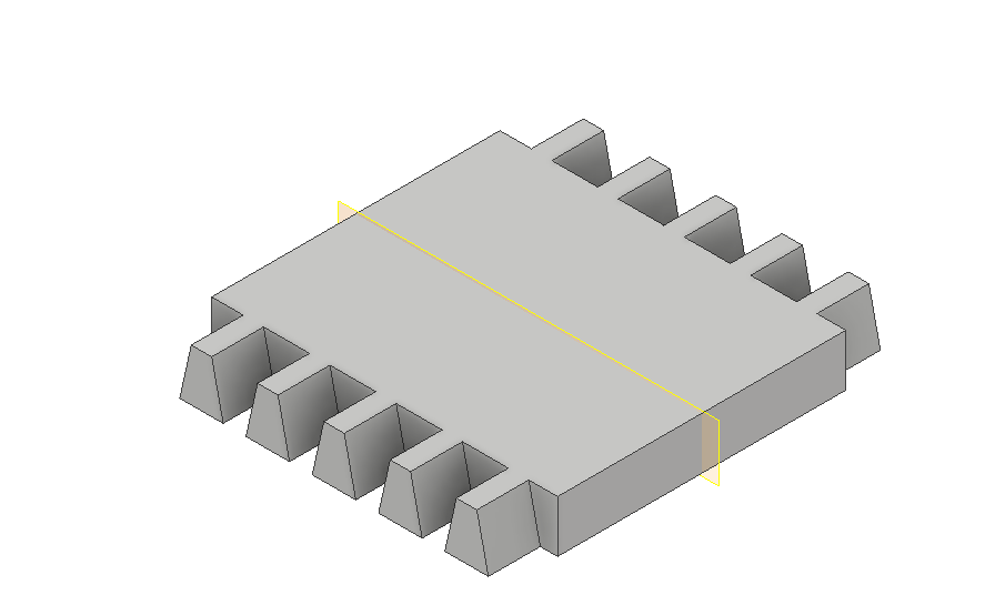
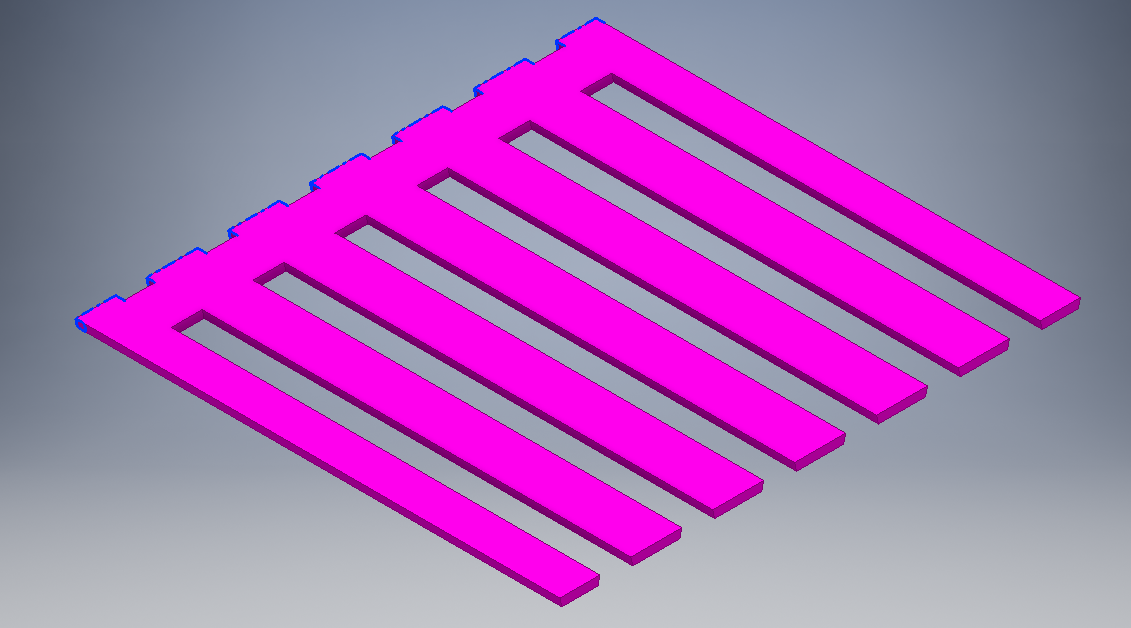
I did the same for the side parts using diffrerent technique like mirroring. They are three side parts as shown.
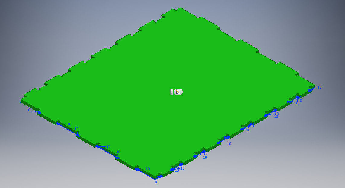
Final sides designs
Door part
Started with a rectangle sketch then gave it dimensions. I did another sketch on the side view to create the sliding door. Then mirrored that sketch to the opposite side of the design.

Assembly
CAM process
First Design
Computer-aided manufacturing (CAM) is the use of software to control machine tools and related ones in the manufacturing of workpieces. CAM may also refer to the use of a computer to assist in all operations of a manufacturing plant, including planning, management, transportation and storage.Its primary purpose is to create a faster production process and components and tooling with more precise dimensions and material consistency, which in some cases, uses only the required amount of raw material (thus minimizing waste), while simultaneously reducing energy consumption.
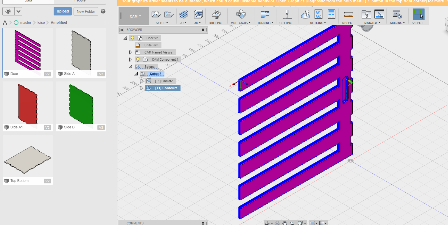
I used Fusion360 to generate the Cam for the design. I went to Autdesk online and created an account then signed in, downloaded the installer and installed it in my laptop. This is to aid in the test runouts , alignments, speeds , feeds and toolpaths for the machine while cutting out the specific designs provided to it. Using this software I specified the neccessary requirements for the parts to be cut out from the wood by the CNC machine. I will just break it down using one of the parts. I did all the parts individually and generated the Gcodes for each.

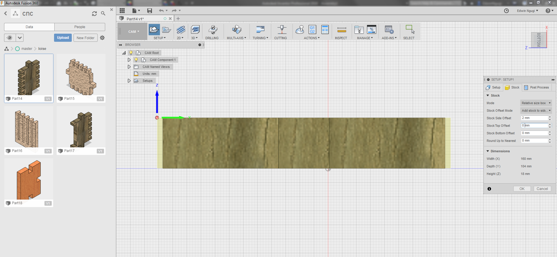
Opened Fusion360 then created a new folder and named it.Then I uploaded the parts that I needed to make the container as you can see on the image. With the help of our lab technician here at Gearbox who assisted me in understanding the whole process for CAM and why we using it. He told me we needed to generate a Gcode fot the CNC machine and be able to select the necessary tools involved and dimension, plus the axis has to be aligned in the right place.Begun by chosing Cam from the drop down then selected the part to generate Cam for in this case its part14 as shown.
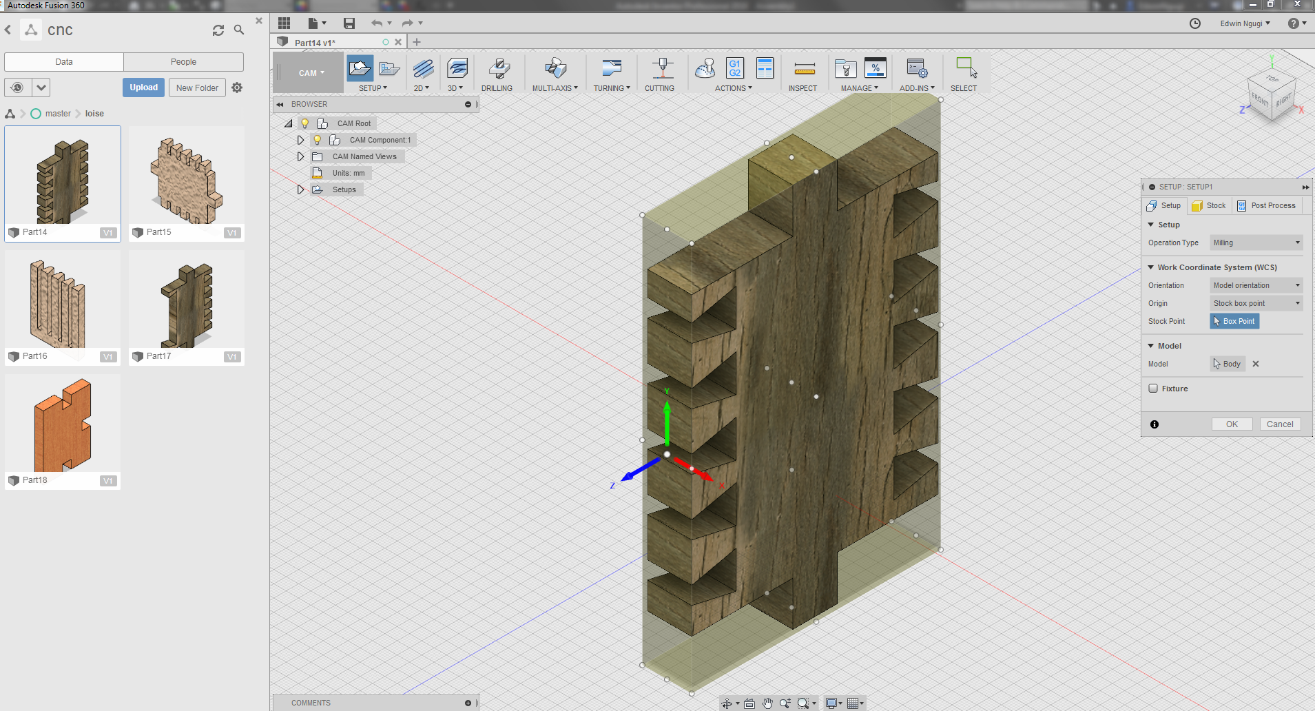
The first step was to align the axis at the right point of the design. Just moved the axis and rotated it so the x-axis can face the upperside to create a positive cartesian plane at that point.Where you put your axis matters because that determines how th emachine will cnc your work.

On the stock link worked with the offset where we had to specify the measurement to offset from the design to the tool. On the circled point is where the offset setting are, in this case worked with the side and top and since for the top am using the exact size of the material which is 18mm then the 2mm is not required since it will mill the material and I dont want that. For the side view I offset 2mm.
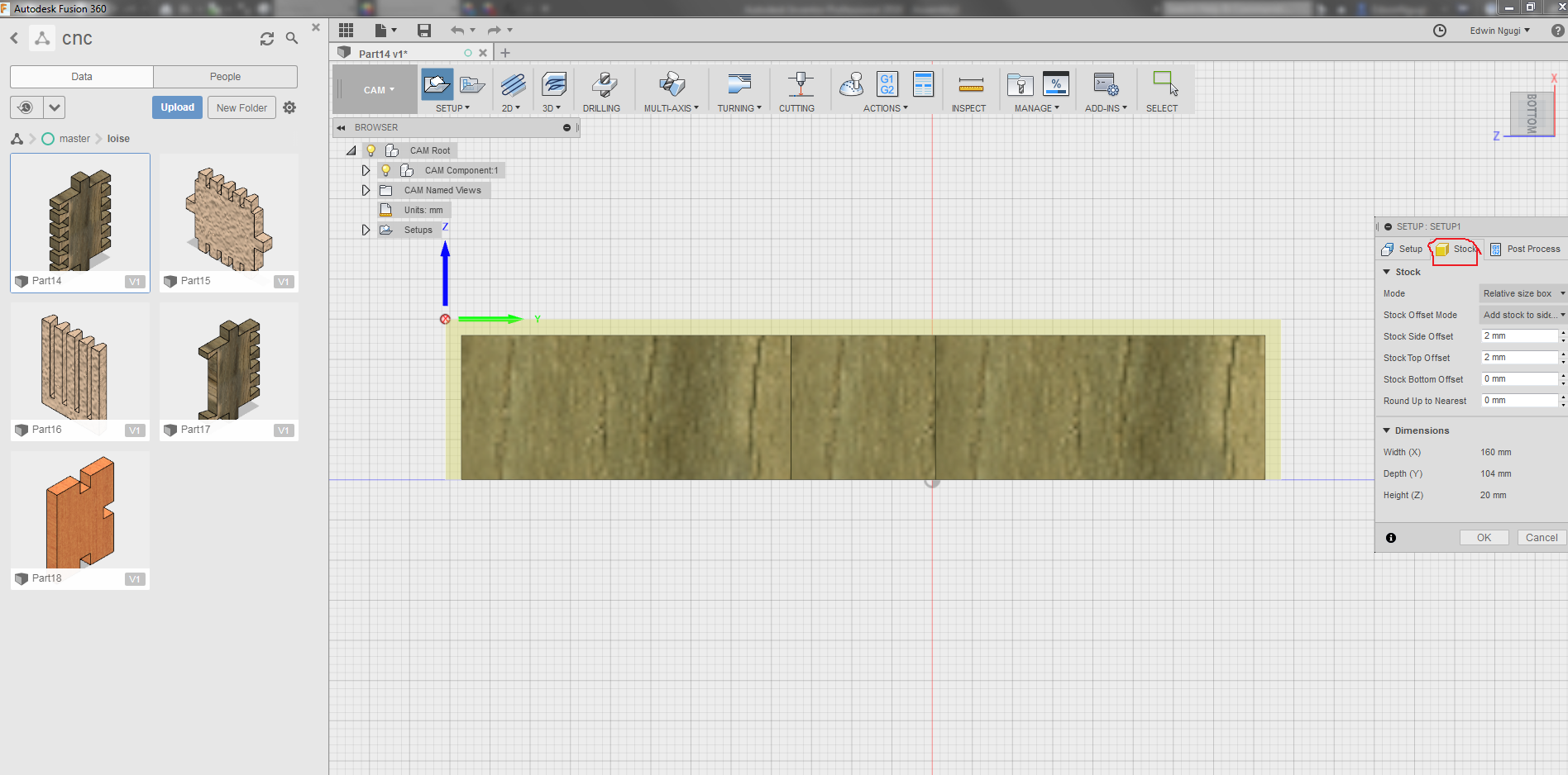
You can see the difference from the above and the below diagram where the offset changes have been actualised.
The 2D contour is where I selected the tool that I wanted to use and specified the speed and feedrates. Here i selected the flat end milling tool.
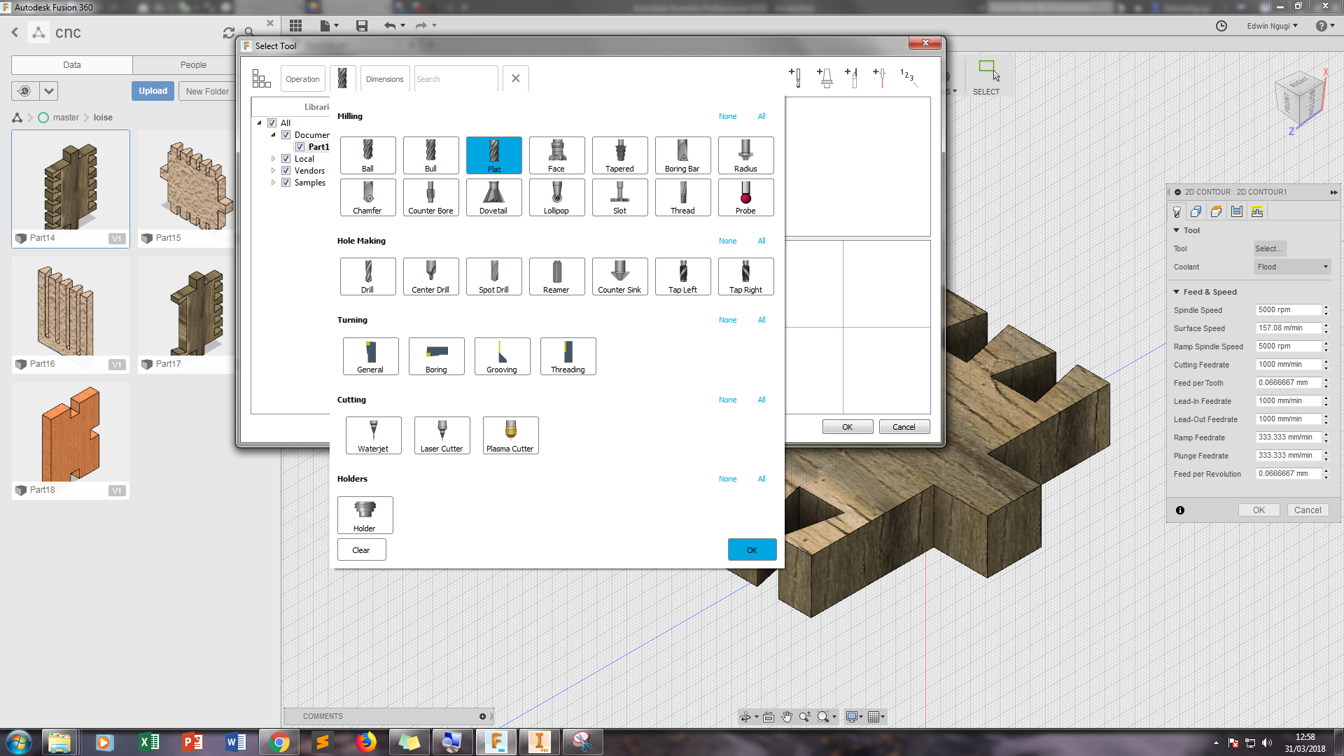
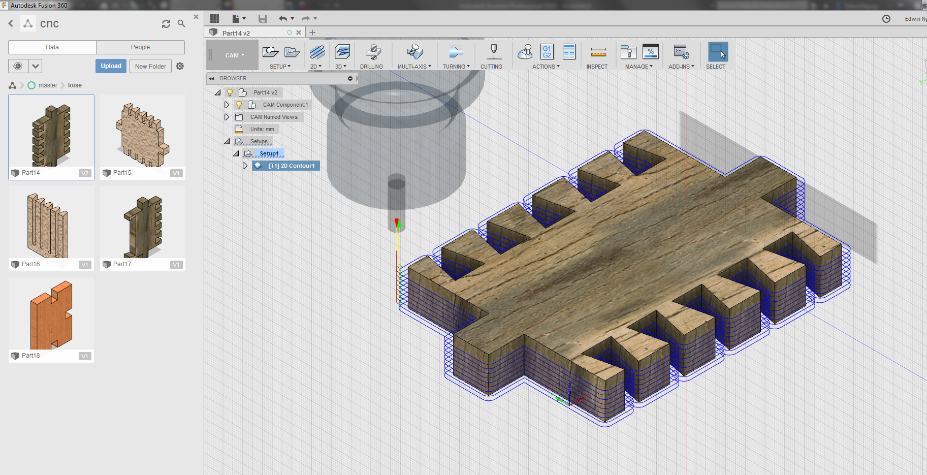
Then used the tool to generate the created tool path for the design as shown to ensure that the tool is able to mill all the necessary sections of the design as shown in the diagram below.
Second Design
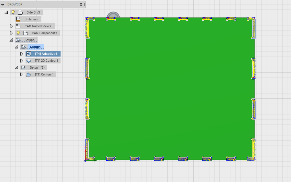
For the second design I followed the similar process as the first design using Fusion360 software.

A video of cam process simulation.
Machining Process
First Design
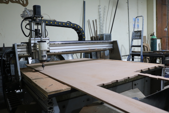
For machining process since our plasma machine is for both wood and metal I had to change the table and the tool head with the help of collegues at work and supervisor. after setting the bed we placed the wood ready for cutting. This is me cutting out the unneccessary piece of the wood. We held the wood piece in place.
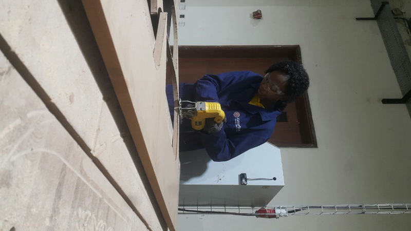
After that it was controlling the machine using its control computer panel as shown. We had downloaded the Gcodes and stored them in a flashdisk that we mounted into the computer for the CNC machine. First you home the milling tool using the go to zero the you use dthe arrowa to position it to the the tool where you yant it to be, then configuring it usng the x , y and z points as shown in the screen
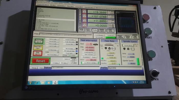
I set it to start milling by using the start cycle button.
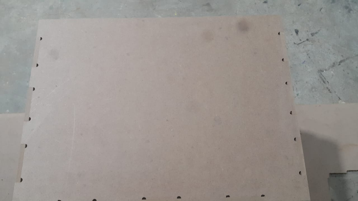
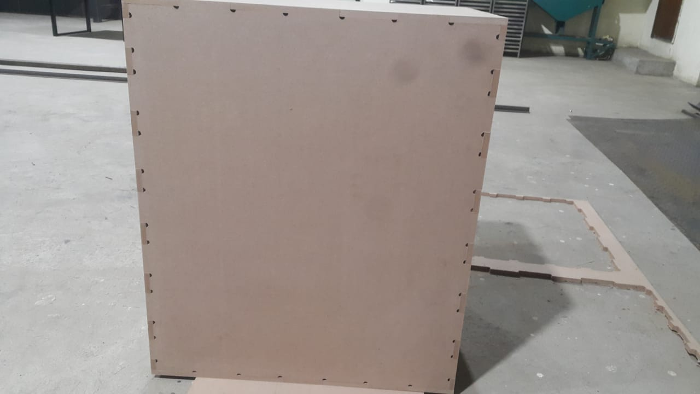
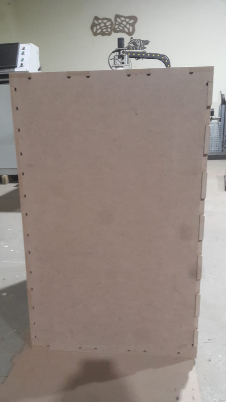
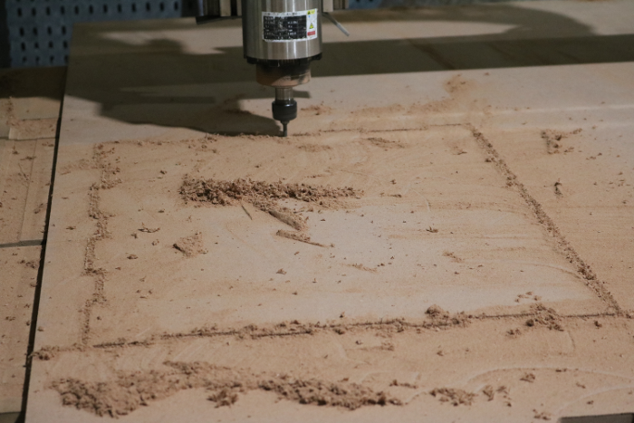
I did the same for the other parts as shown.

Second Design
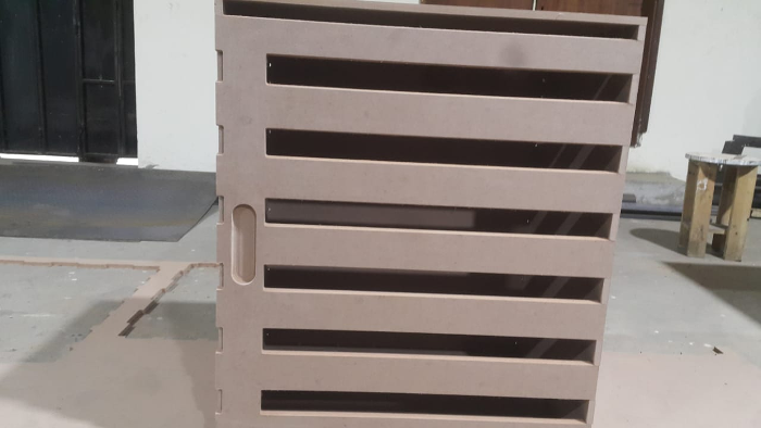
For the second design I scaled it up to make a bigger wardrobe.

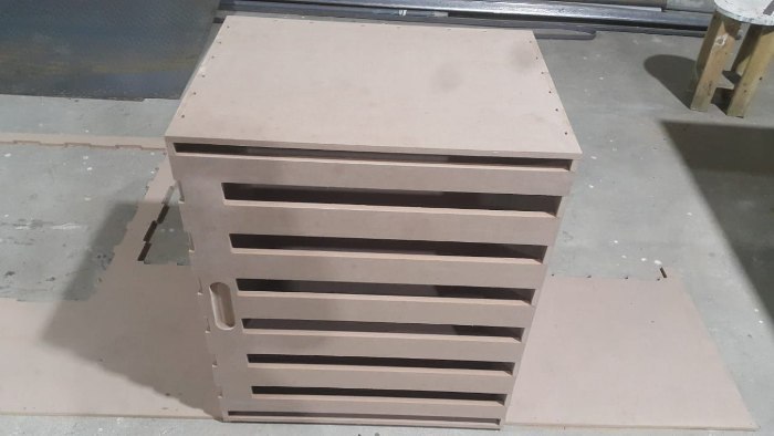
Final Results
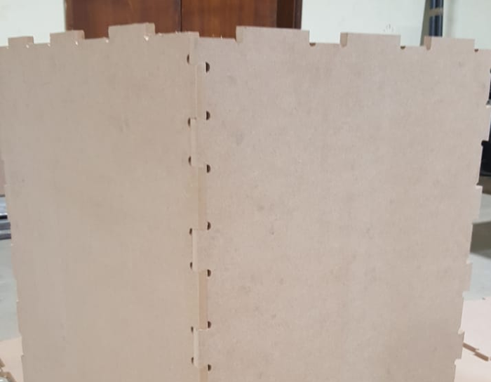
Complete parts as shown below.
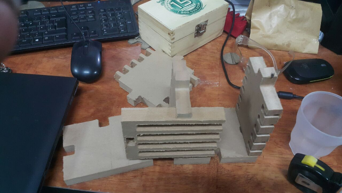
As I learnt later the corners of the design with rounded and not sharp as expected so the joints cound not pressfit together so I went back to the drawing board to find a solution since the machine can not accomplish a sharp corner.

Second Design
Hero shots.