Final Project
1.1. Concept
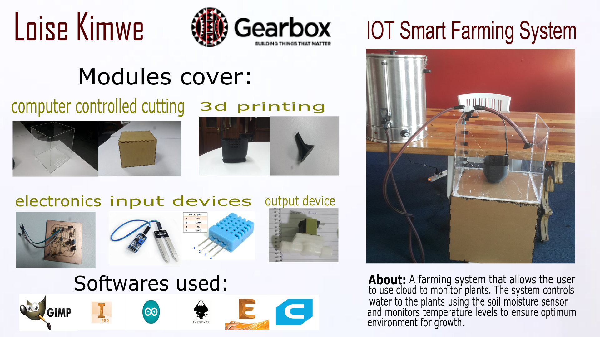
IOT Smart Farming System
Farming is a big deal hear in our country since many families depend of farm produce to earn a living and a sustainable income. The idea behind the whole concept is to create a solution that will be able to service both small scale farmers and large scale farmers, who will this system help? Water being such a huge resource and neccesity in the farming process, we hope to aid in monitoring and cutting out on extra cost incurred when water get wasted.It is a system that aids in ensuring the proper conditions for plant growth by monitoring the moisture levels, light and temperature levels of the environment. A system that will automated the water supply and also checks the conditions like temperature, light exposure and soil moisture levels to enable the farmer to optimise on the resources available. The goal is to help the farmers be aware of the conditions in which their plants are growing and give them the feedback in the comfort of their gadgets. The system should be able to analyse data and provide necessary feedback to the farmer. With the integration of a wifi module the data collected form the farm will be send to the application.
Idea
To demonstrate the idea I will be automating the watering sytem and monitoring the water usage that the plant will be using as well as the temperature. To ensure the autonomous of the sytem the watering supply will be automatically be opening and closing depending on the soil moisture levels of the soil.
1.2. Plan and Resources
Planning phase
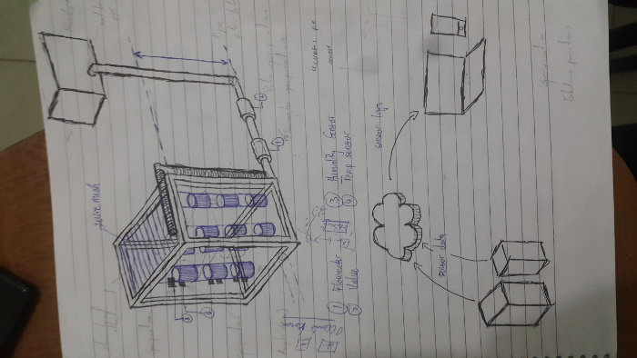
In this phase I will be making different parts of the project using different materials and in separate ways then interconnect them together to make it complete.
These include;
i). Plant Encasing
This will hold the plants and soil.
ii). Container
This will be the body simulating the environment.
iii). Sprinkler
This will be used to sprinkle water to the plants.
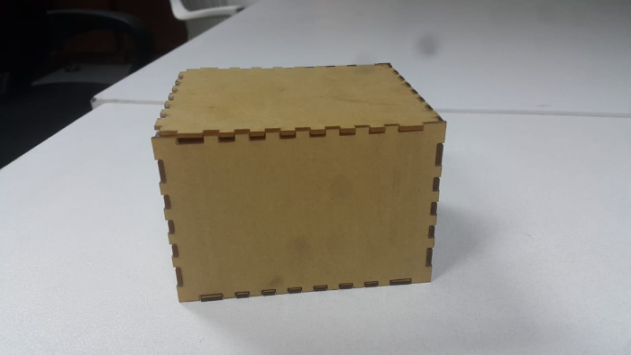
iv). Electronics box
This box will be containing all the electronics required to control the whole system.
iv). Water tank
It will be a tank that will hold the water.
iv). Pipe
Pipes will be used for passing water from the tank.
iv). Intergrating all the parts
This will involve taking the different parts and intergrating them where necessary to produce the final expected results of the project.
Resources
1. Soil Moisture Sensor
2. Temperature Sensor
3. Valve
4. Flow meter
5. Transistor
6. 12V DC battery
7. 5V regulator
8. Board
9. Acrylic sheet 8*4
10. Pipe 1/2
11. Atmega328p
1.3. Process
The following processes were used to help in designing the project.
Week 0: Principles and PracticesThis week illustrated the idea concept and what the project will be all about.
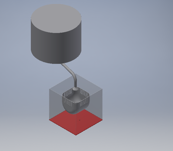
Week 2: Computer-aided design
In this week I designed the plant encasing and the container to be used to simulate an environment using the inventor software. The plat encasing is for holding the soil and the plant that will be watered by the auomated opening and closing of the valve when the water levels are low. The container represents a farming environment whether in greenhouse or a (farm small or large) that has sensors around it to monitor the enviroment.
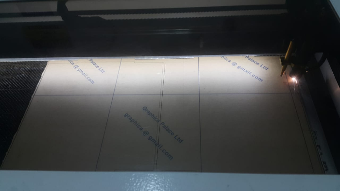
Week 3: Computer controlled cutting
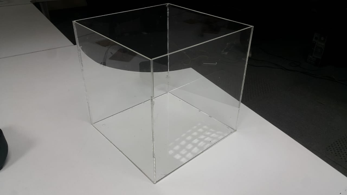
Since am interacting with water for the container I used acrylic material to help manage the water spillage unlike wood. The conatiner as explained above is to simulate a faeming environment. I used the lasercutter to cut the shapes which I had designed as shown below and then I joined the pieces together. Also the electronics box which I used the same material.
Week 4: Electronics Production
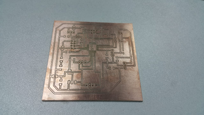
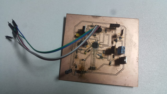
This helped in making the final board by milling it and designing and soldering as well as learning how to integrate different components with the microcontroller. The board I milled using the burngard milling machine in our labs as shown. To mill the board I followed a similar step elaborated in the electronics production week.
Populating the board
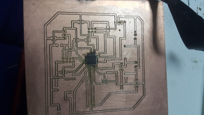
Populated board
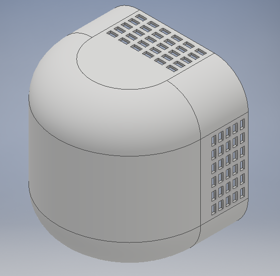
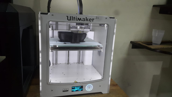
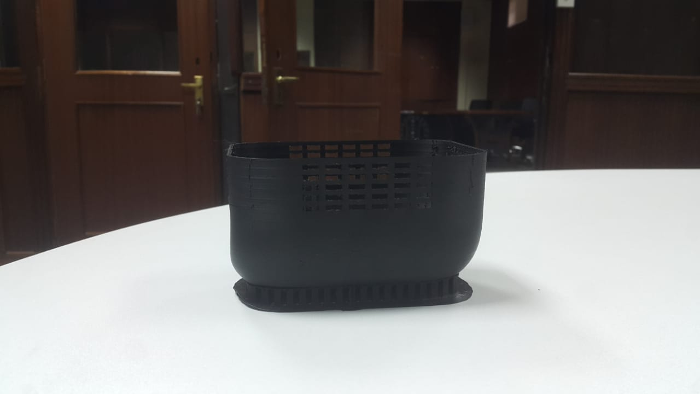
Week 5: 3D printing
The plant encasing was 3d printed with the ABS material as well as the sprinkler for water outlet as shown below.I added the general support for th eplant encasing so that the curved part can be printed properly.Also 3dprinted the sprinkler shown below

Week 6: Electronics design
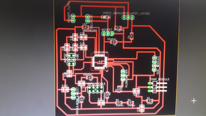
Using the knowledge learnt in this week where I had to learn how to design a circuit board from scratch using software like eagle. I gathered the necessary information to help in executing the final board with minimal errors unlike my earlier experiences with the other boards where I had to go back and forth for either tracks being too thin and not placing the component in the correct pin for the micro controller. To design the board I used eagle and first started with reaserch on different component connections then I did the schematic as shown.
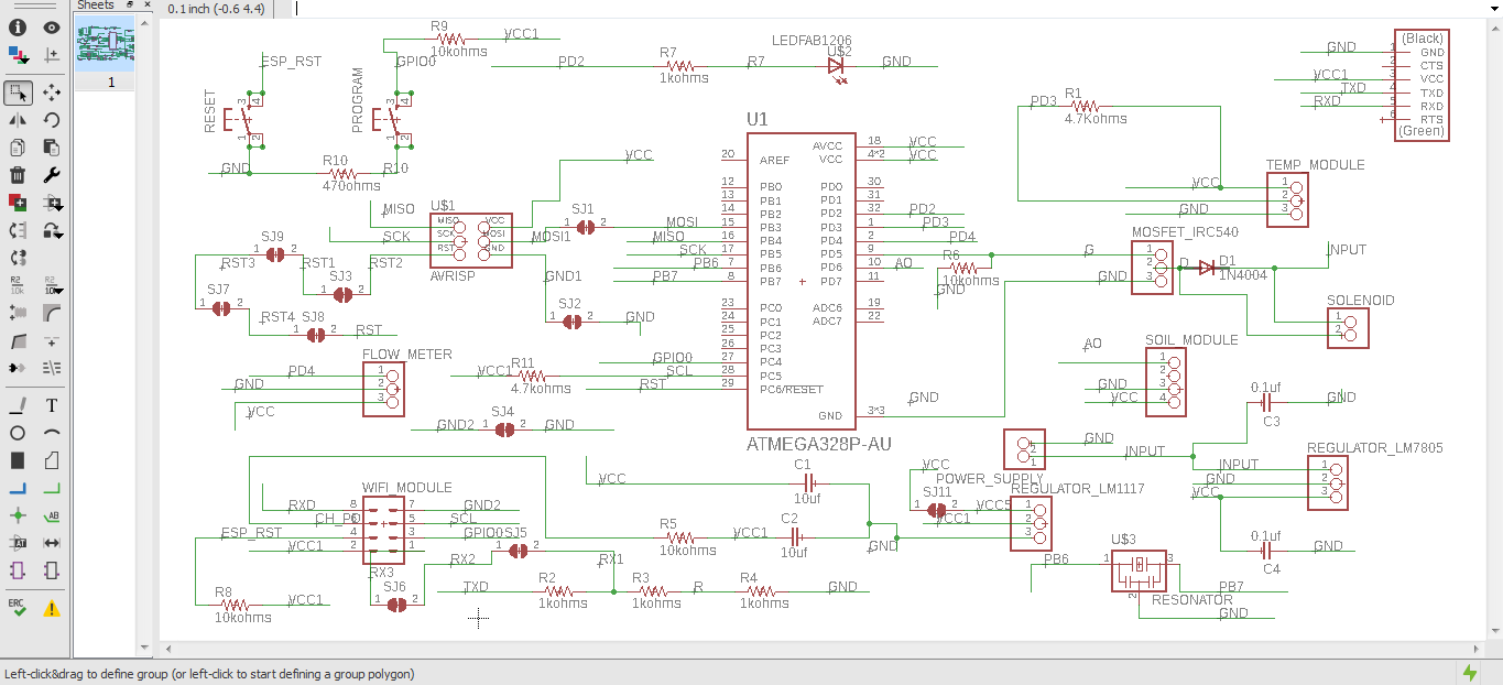
To generate the design for the board used the schematic button. Using routing tool to connect the components together based on the connections from the schematic board designed above.
Week 10: Input devices
Several input devices where used for different reasons which include;
Soil Moisture sensor
To monitor the amount of moisture in the plants, a soil moisture sensor is mounted to check on the amount of water present for the crops at all times. This helps to identify when the moisture is either high or low and then it sends the information to the system so the appropriate action is taken depending on whether the moisture level is high or low. To water the plants properly and ensure that they are maintained in their optimum health throughout their lifecycle, the moisture level is expected to be optimum at all times.
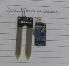
I used the arduino ide to program the soil moisture sensor which has 3 pins were one is for collecting data. the data pin I connected with the analog pin. The soil moisture sensor takes the readings as shown in the first code.
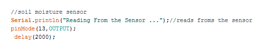
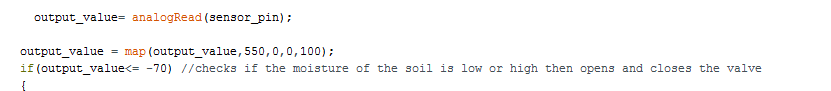
The dry soil has a different reading compared to the wet soil. In the code below at first i tested the two soil ranges to get the value that will make the valve open or close varying with the soil input.
Temperature sensor
The temperature of the environment in which the plants are grown is of great importance, to measure the temperature and the humidity, a temperature sensor is incorporated into the system. This helps with collecting and distribution of the data from the plants to the cloud. To maintain a good variant in the moisture, temperature and humidity content, the readings have to be regulated so to allow the crop to develop properly through its lifecycle. The right soil acidity levels is maintained by regular check ups and understanding the collected data for the sake of improvement of the crops.
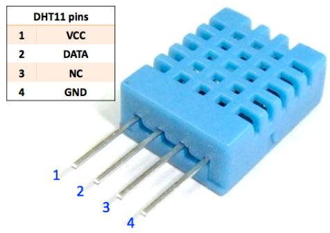
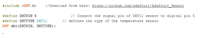
The DHT11 requires a library for it to be programmed, using the link shown in the code below to download the library then installed it in the Arduino IDE. Define the data pin of the sensor and the type of the temperature sensor as shown.
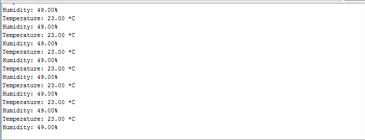
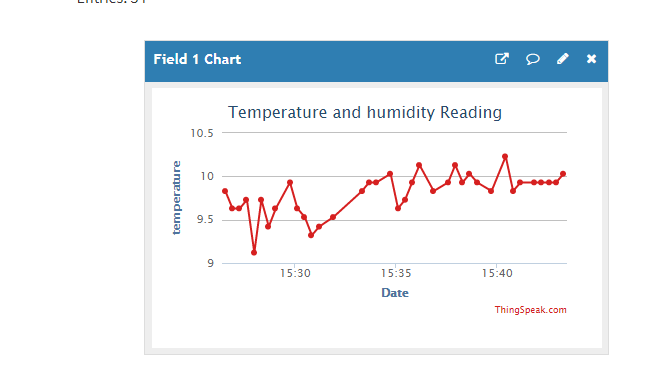
The temperature and humidity readings.
Week 11: Output devices
the project as well had an output device which is the solenoid valve as shown below;
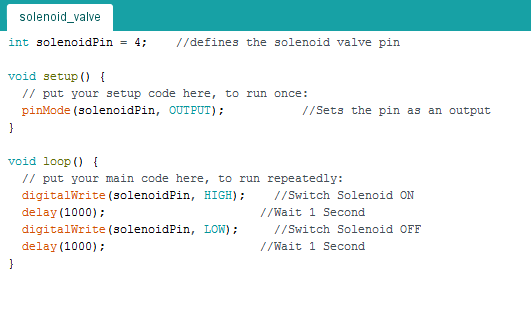
Solenoid valve
As a part of the system, the valve is attached to the system moisture control system, it regulates the movement of water to the sprinkler so as to maintain a conducive amount of moisture to the plants.The valve allows water to flow for a designated period of time and then when instructed by the the system, it shuts off when the moisture level is deemed optimum by the moisture sensor.

Start by defining the solenoid valve pin , then set it as an output as shown. The valve opens and closes when with a delay of 1 millidsecond as shown.
Since the has a wifi module that sends data to an online application as follows. Before I could start programming the wifi module i went through several tutorials and how it works and several ways of connecting to it and finally I settled on using the Thinspeak which is an open Iot and anlytics platform to connect to the module and present that data in the cloud.
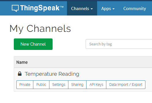
Visitted the Thingspeak website and created an account.

After creating an account. Go to channels and create a new channel as shown. I had created a temperature reading channel as shown.
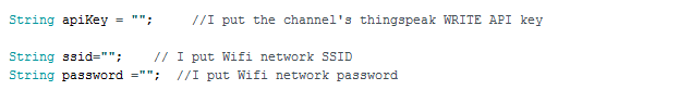
Once you have created a channel. There is a section for API keys where you are provide with a key to use in the code as shown. Copy and paste the key in the key section. For Thingspeak to be able to connect to your wifi mode you write the wifi and the password of the wifi in the settings shown. The module uses the setting to connect to the internet.
ESp8266 wifi
The wifi module collects data from the temperature module and relays to the cloud in real time that is th ethingspeak iot platform where it is displayed.
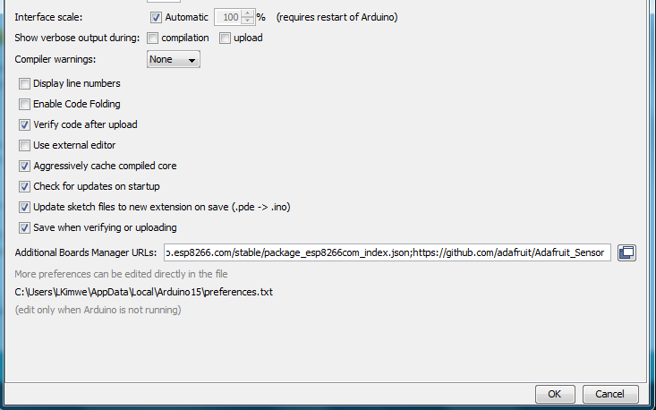
The espwifi module requires a library for it to work. In the Arduino IDE go to files , then preferences from the preference prompt added a link as shown. Then go to Tools under the boards manager look for esp8266 community library and click install.
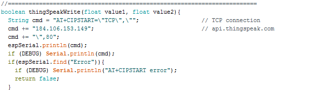
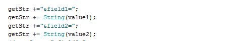
Thingspeak connection using the tcp through the esp wifi module as shown. It is important to include the necessary library links to your code.
These gets the data from the DHT11 temperature module.
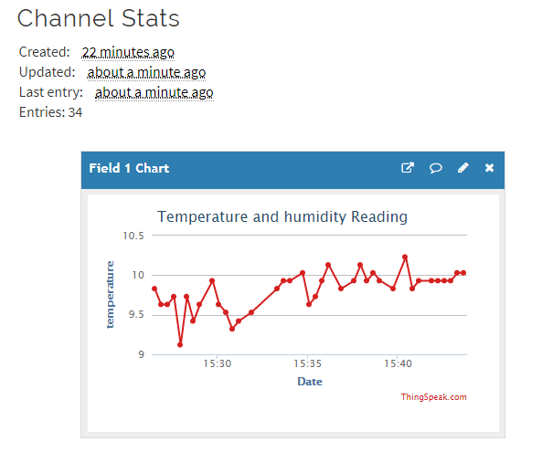
The data get dislayed as shown.
Assembly
The assemblying process involved a bit of handy work, this included ensuring the pipe fits perfetly to the solenoid valve to avoid any leakage. Before getting into that at first made sure I had all the components that I required for bringing the project into life, starting with the below bill of materials from the board schematic.
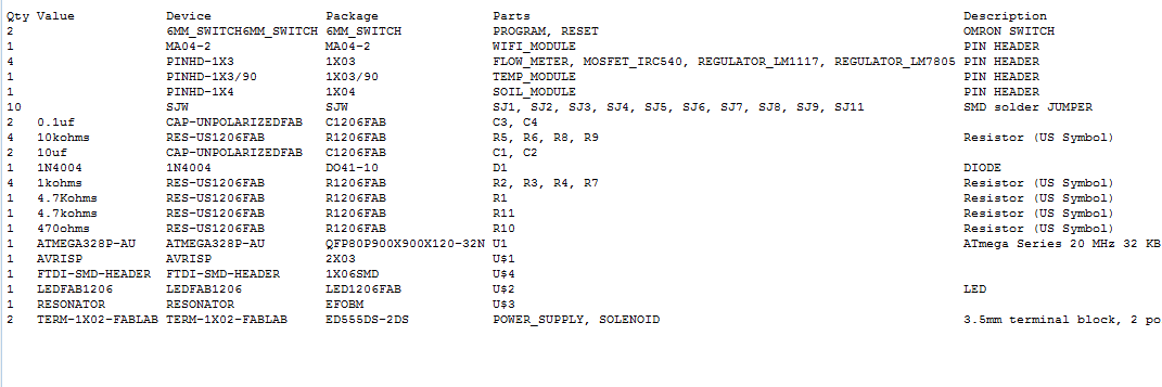
Using the components listed above I populated the board as shown below where I used the soldering iron and soldering wire. while soldering I ensured that I have tested the continuity of the tracks and there where no short circuits within the board, using a multimeter.
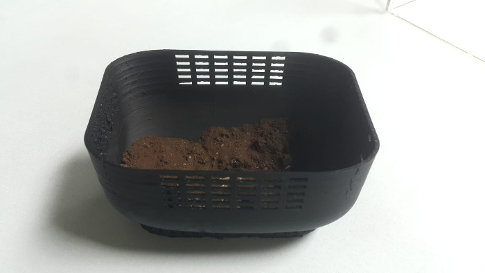
I assemble the container as well and for the plant encasing i put a sample of soil one side dry and the other side moist.

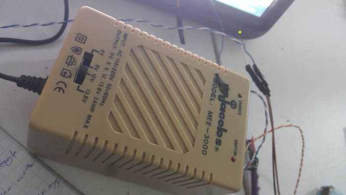
For power supply the solenoid valve uses 12v so i outsources for one. The solenoid valve was a half inch thickness which requiredsame thickness for the pipe which I happen to find with no expense incurred for both.
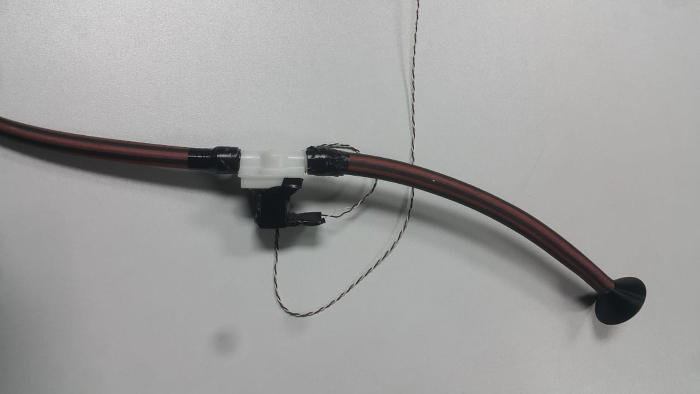
I joined the pipe to the solenoid valve as shown and to make it air tight I used tape to seal it in place. As well I also added the sprinkler which is also the same size and placed it on one side.
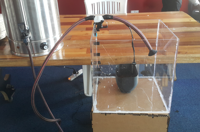
Finally assembled everything together as shown. The tank was for providing water supply. I sealed the container properly to avoid any water leakage.other parts included; the soil moisture sensor, temperature sensor, solenoid valve, palnt encasing and pipe.
1.4. Results
Since the project revolves around water I first tested to see if the soil moisture is able to operate together with the valve, where if the soil is dry then the solenoid valve opens and if the soil is moist then valve closes automatically. To test at first I went to in our kitchen where I have control of water. The sensor could sense when the moisture of the soil is low and when it is high as swhon in the video. In the plant encasing I put one side dry soil and the other moist soil.
After that I looked for a water supply source and assembled the project as shwon in the video with the results.The readings from temperature module is send to the cloud system as shown..
Poster
1.5. Conclusion
Acknowledgements
Through your support the project has come to be a success,am grateful for time, guidance and resources. Gearbox team, Fabacademy foundation and everyone else who participated in enabling the whole process. Thank you.
