keep steadyappear to reduce the speed.
I tried serveral times untill I have a good result, then select OK to end the process and click on
 to fill the object and make it solid. the result was:
Through this week we have learned about 3D scanning and 3D printing technologies. I scanned an object, then printed it, I also used two different 3D printers methods SLA and FDM using three printers.
3D scanning is converting physical object's surface to a digital 3-dimensional representation. 3D printing is the opposite process that convert 3D digital object designed by any CAD software to real physical object from many materials such as PLA, ABS,...etc.
There are many technologies for 3D printing and scanning. In our lab the 3D scanner is an infrared IR scanner. Printers are FDM Fused Deposition Modeling and SLA Stereolithography 3D printers.
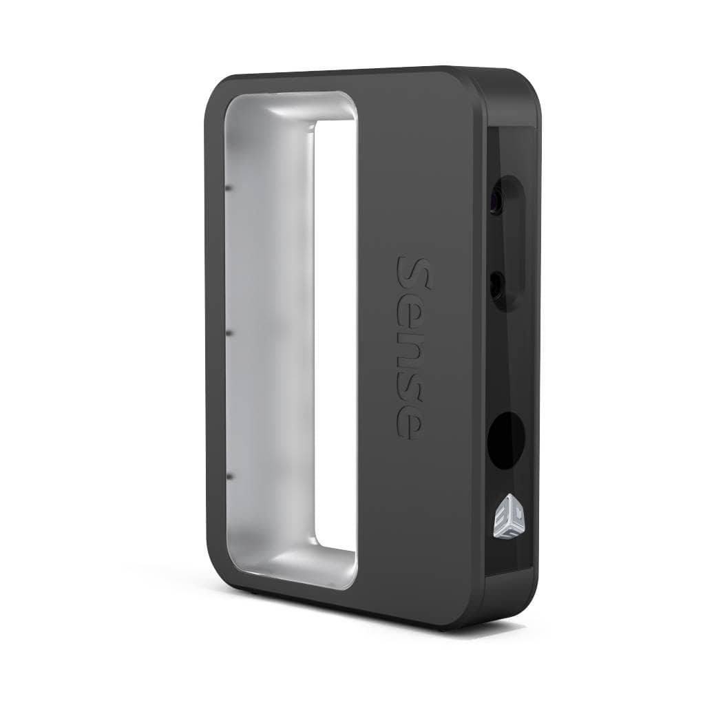
The first task was to scan an object, then print it. I used Sence 2nd generation 3D scanner from 3D SYSTEMS .
to begin the process download 3D Systems Sense a free software from the manufacturing company
website .
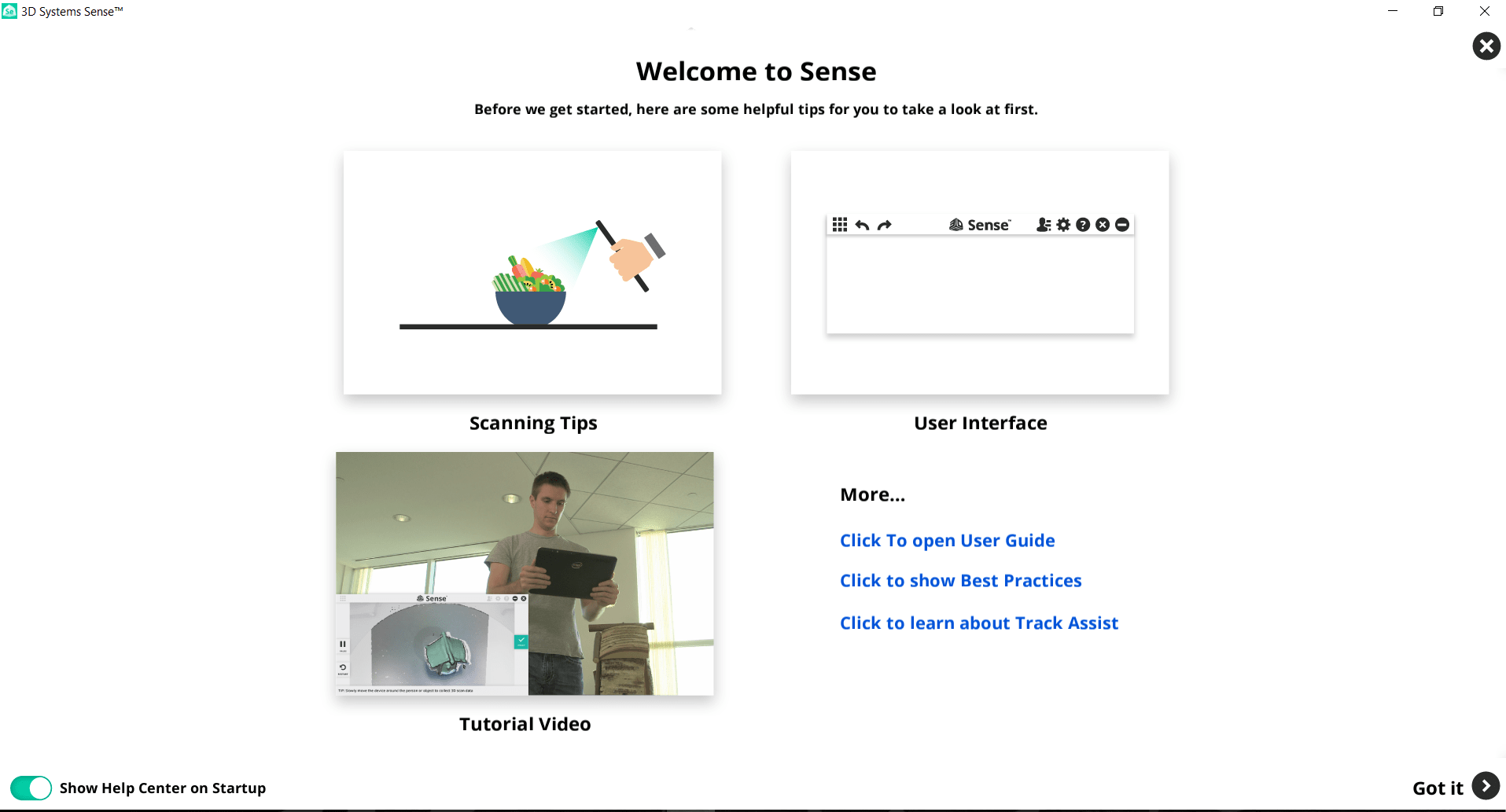
Software welcome screen press on Got it
Then you asked for the verification code which come with your scanner. Then connect scanner with USB 3 port USB 2 don't work!. Make sure there is no error message appear, for example the error shown means your computer cann't fined the scanner!. Try to change the port and restart program after close all other running programs because scanning process consumes a lot of computer memory

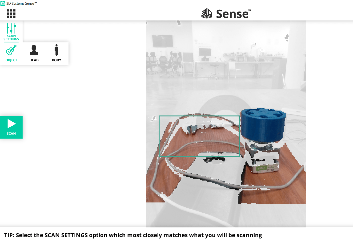
When there is no error message you can start your scanning. I decided to scan an object not a human head so I selected object then Scan option shown:
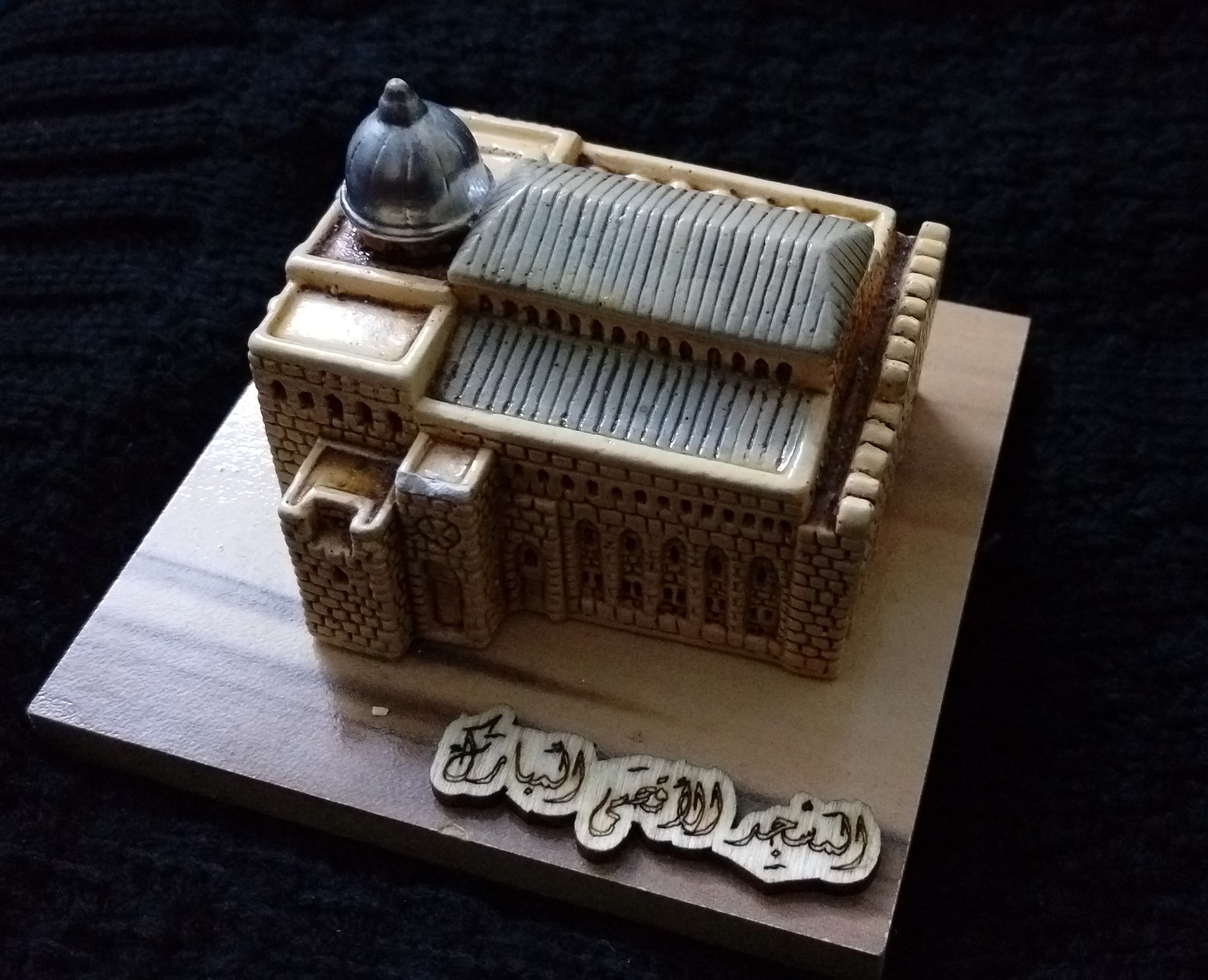
Then put your object on a flat surface, remove other things around it because this will affect your scan I choose this cute o'clock to scan it
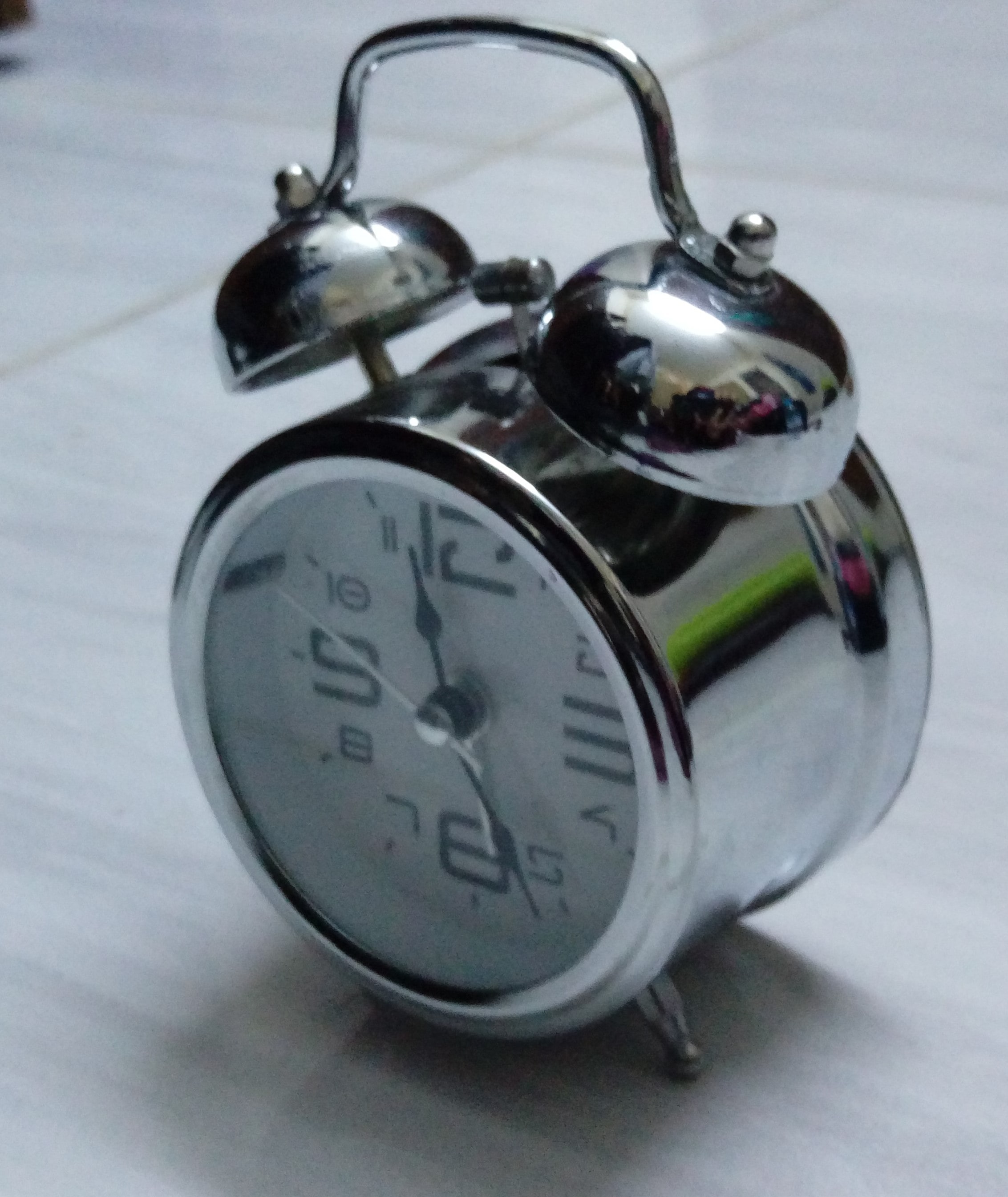
Unfortunately, this object has a shiny surface which effect lights emitted from scanner so the scanner cann't detect :'(
So finally, I found this non shiny object to scan it:
I put this object on a table, press Start triangle button and hold scanner and tried to rotate around the object because this my first time I couldn't keep my hand at a fixed level so the error message Lost Tracking
always appear :(

To solve this problem I put the object on a rotating chair stay in my position and rotate the object, but while I was moving fast the message keep steady
appear to reduce the speed.
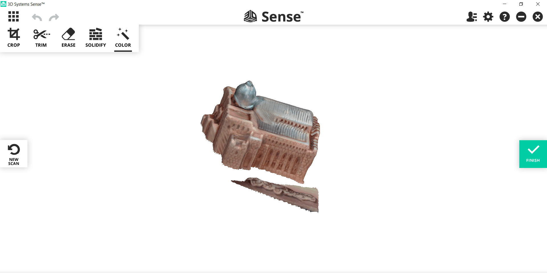
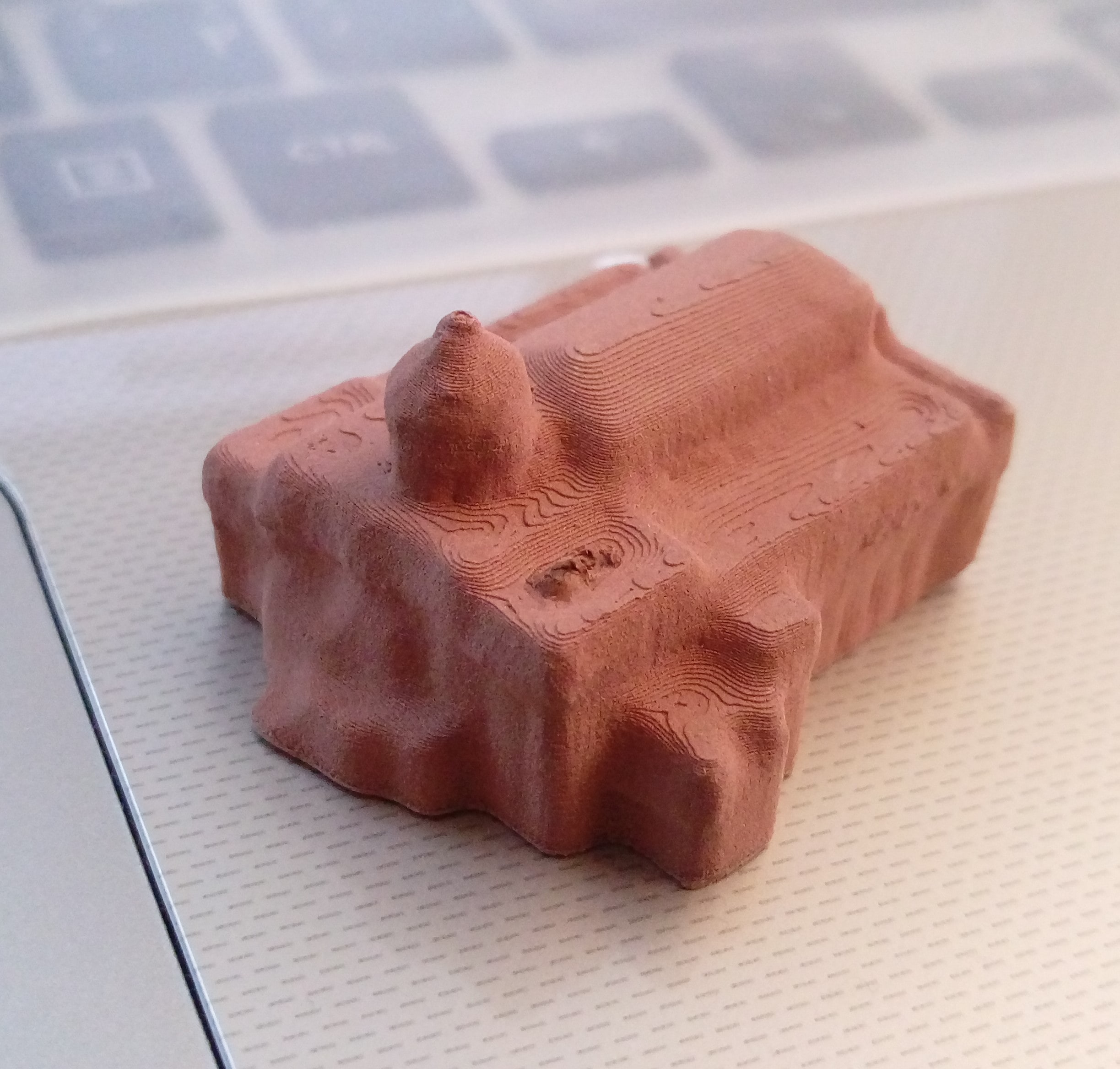
I tried serveral times untill I have a good result, then select OK to end the process and click on
to fill the object and make it solid. the result was:
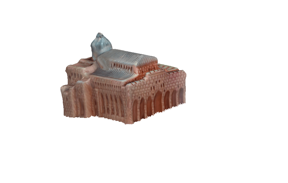
There is some unwanted parts choose
 and select these parts to remove them, the result shown:
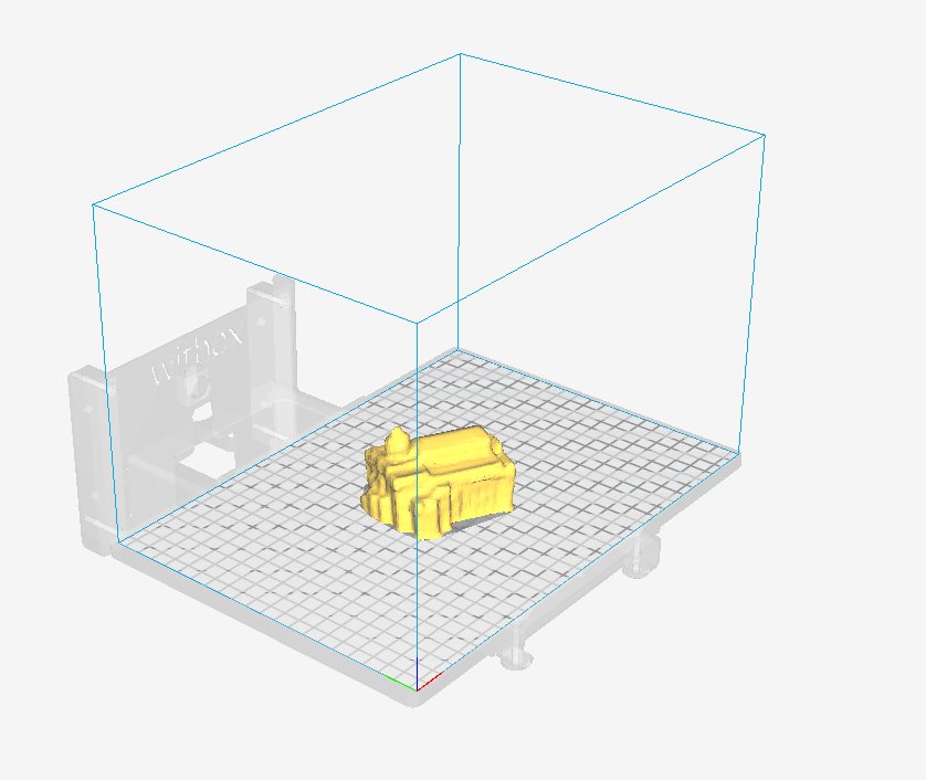
Then select Finish and save the object as STL file.
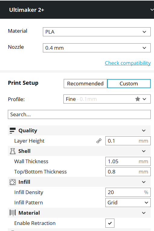
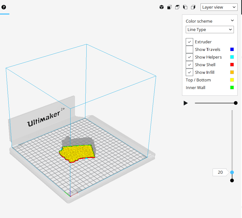
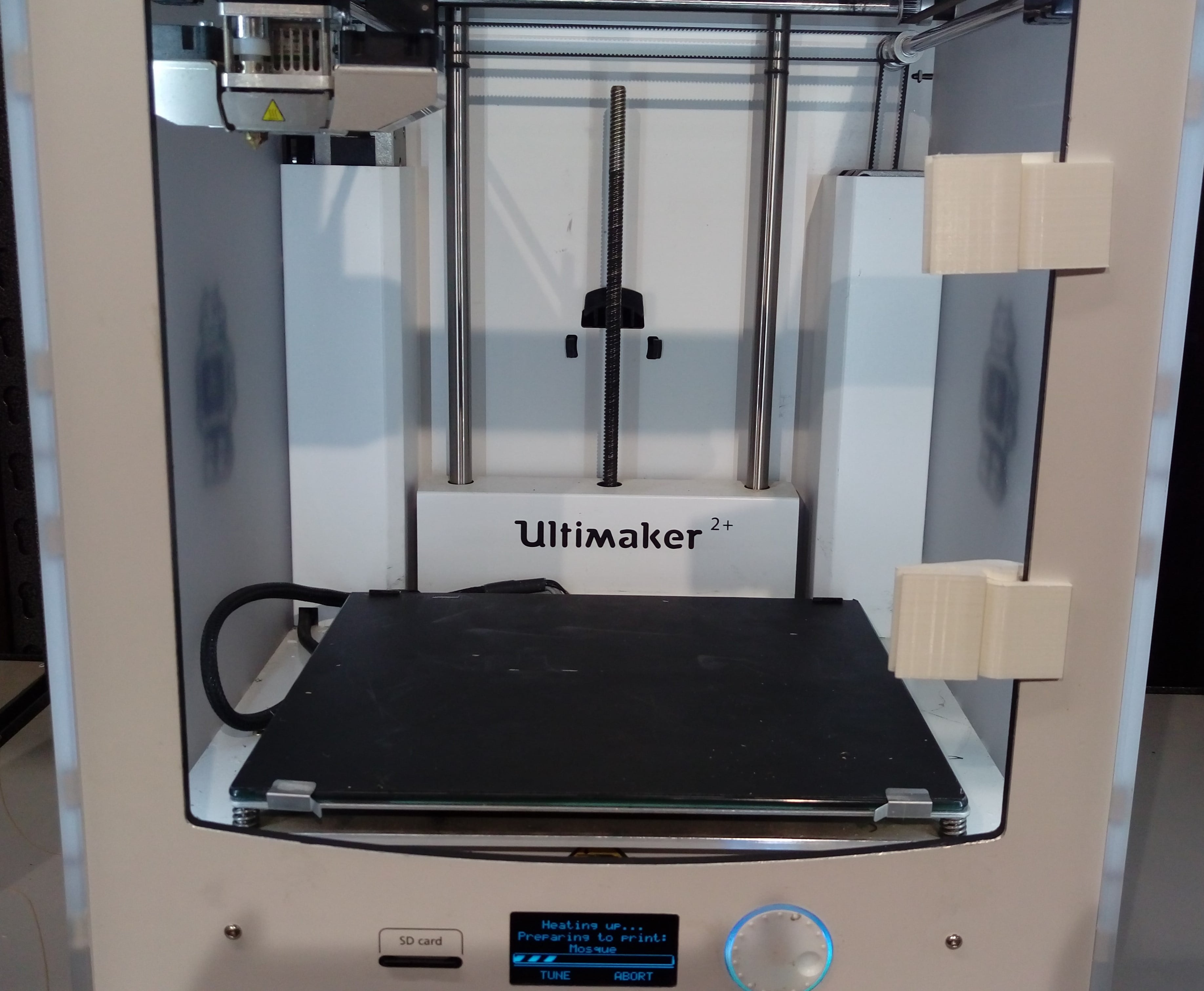
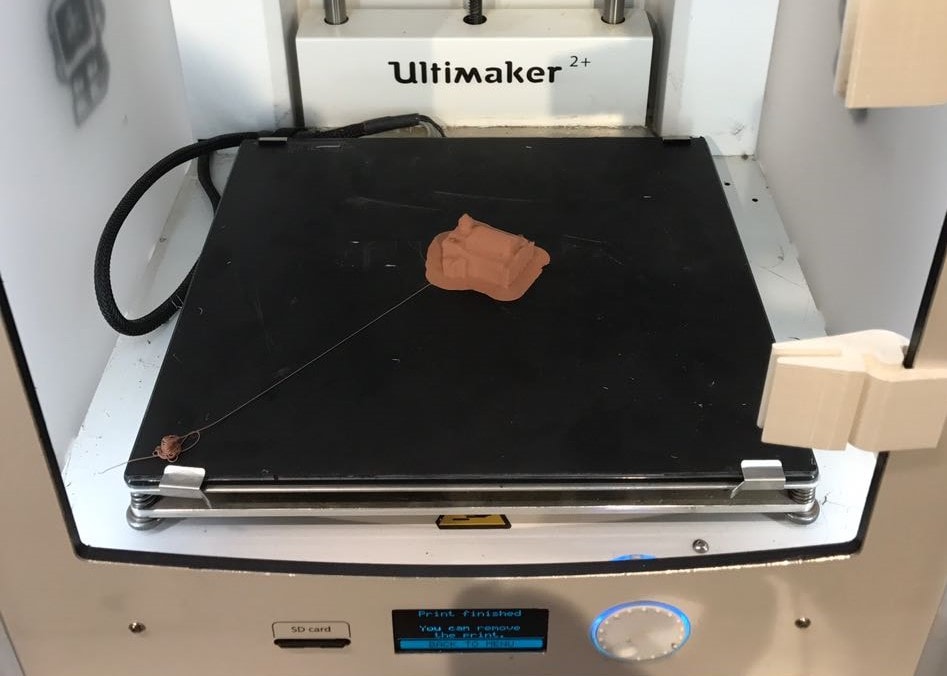
I used Ultimaker 2+ 3D printer to print this scan object using thess steps:
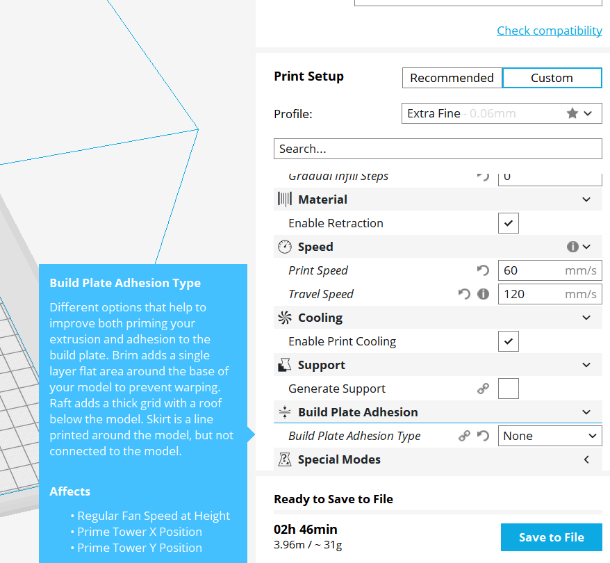
Layer thicknessas this value goes smaller the quality of print goes higher but it will take more time
decrease print speed.
There is an inverse relationship between all speeds and both time and quality of printed object
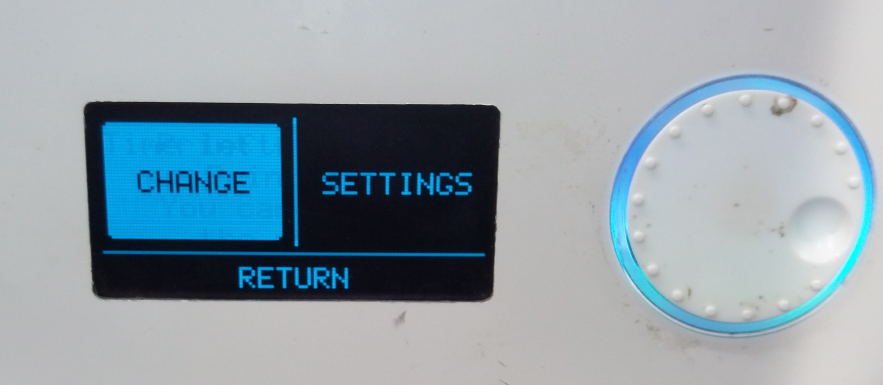
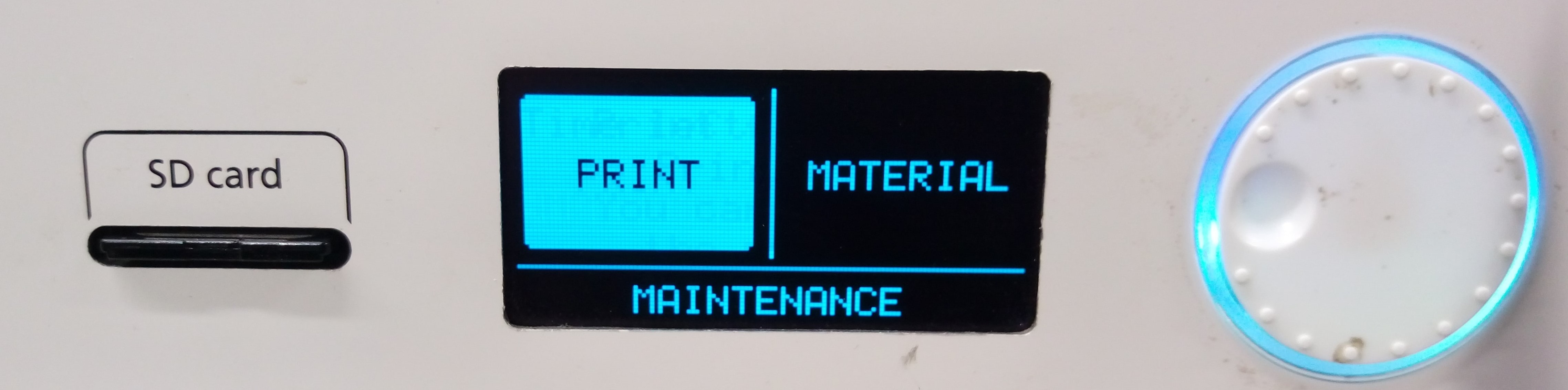
To move between comands rotate the wheel, press on it to select
210C for this copper PLA find te range
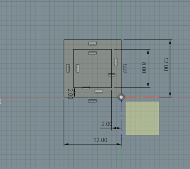
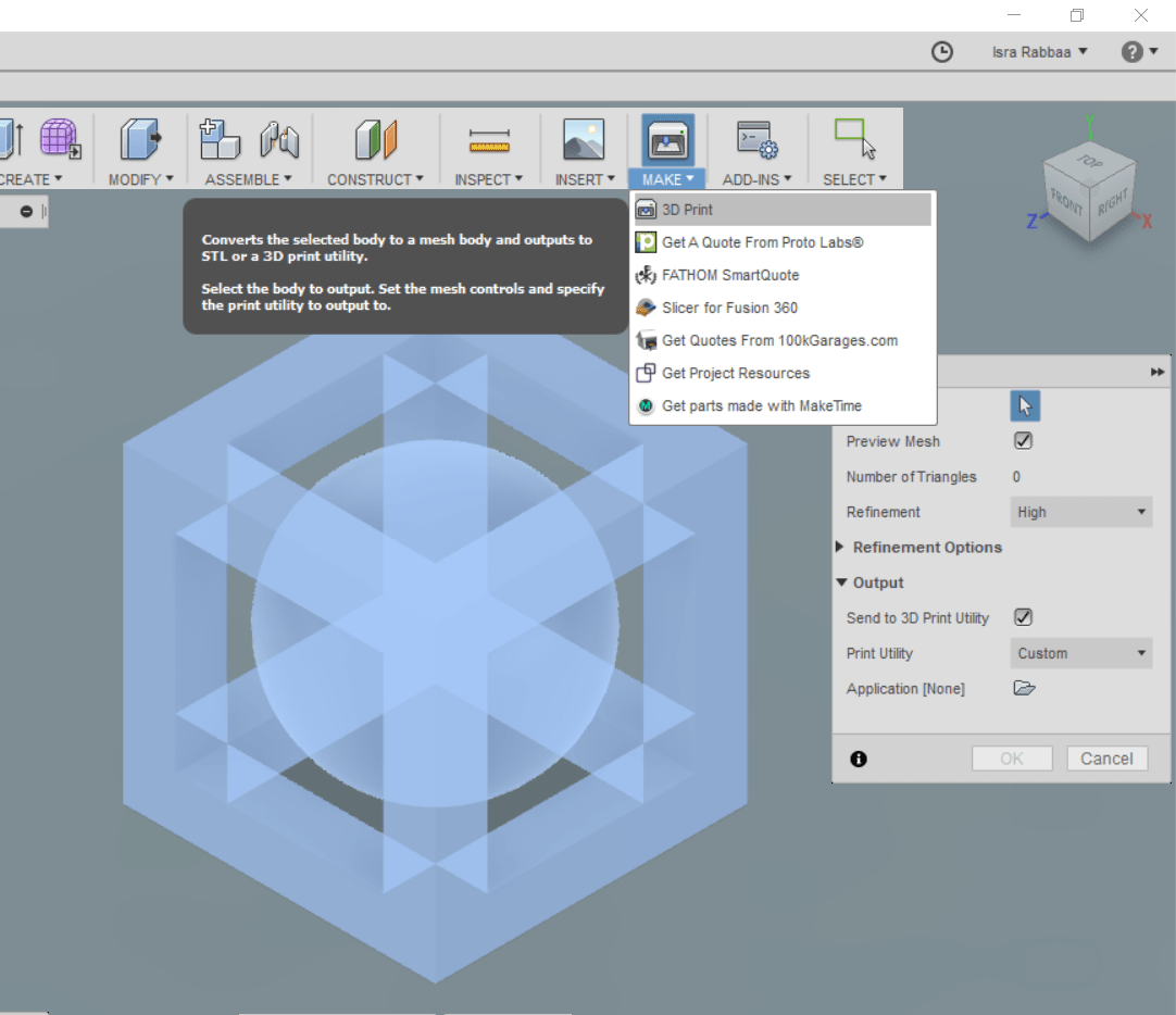
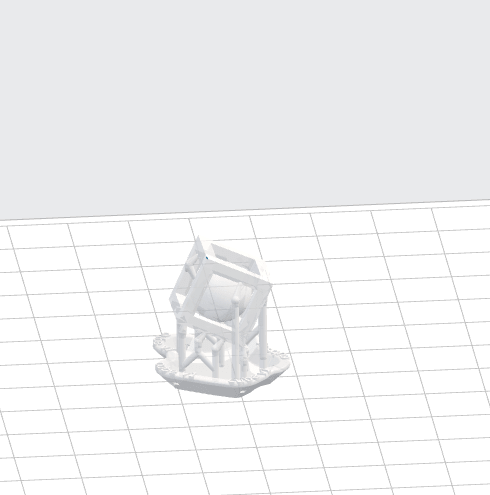
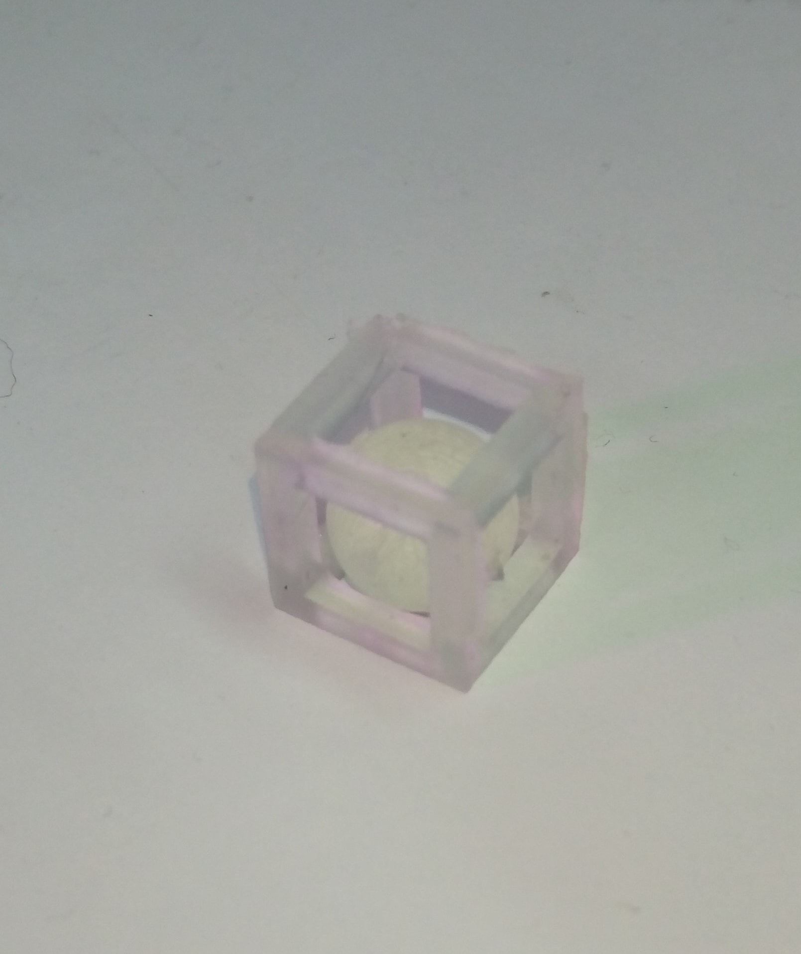
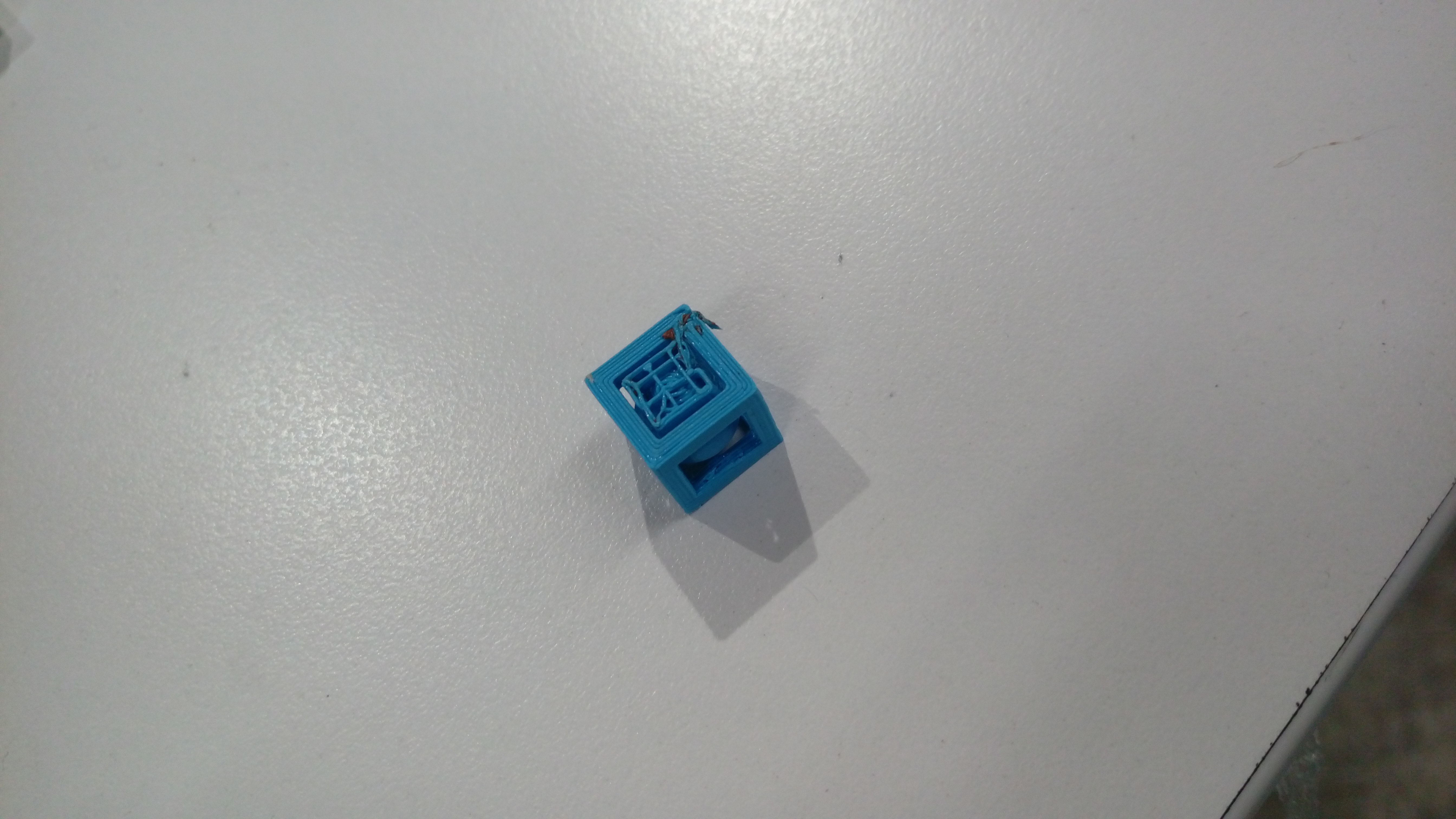
I usedFusion 360 ![]() to design a sphere inside cube in next steps
to design a sphere inside cube in next steps
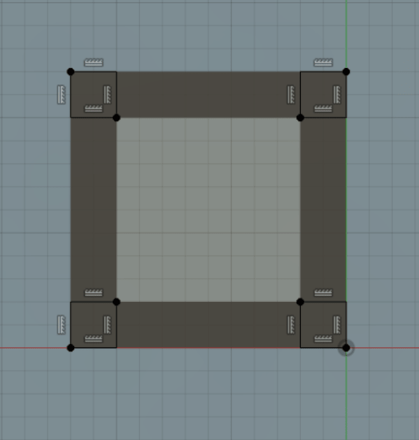
First draw a sketch of two squares with 2mm offset, then extrude it
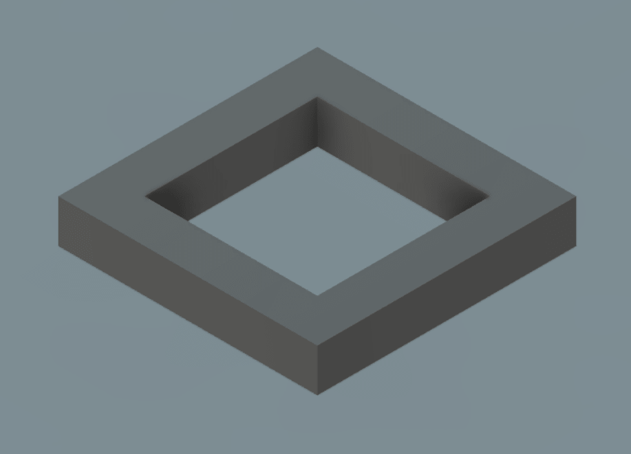
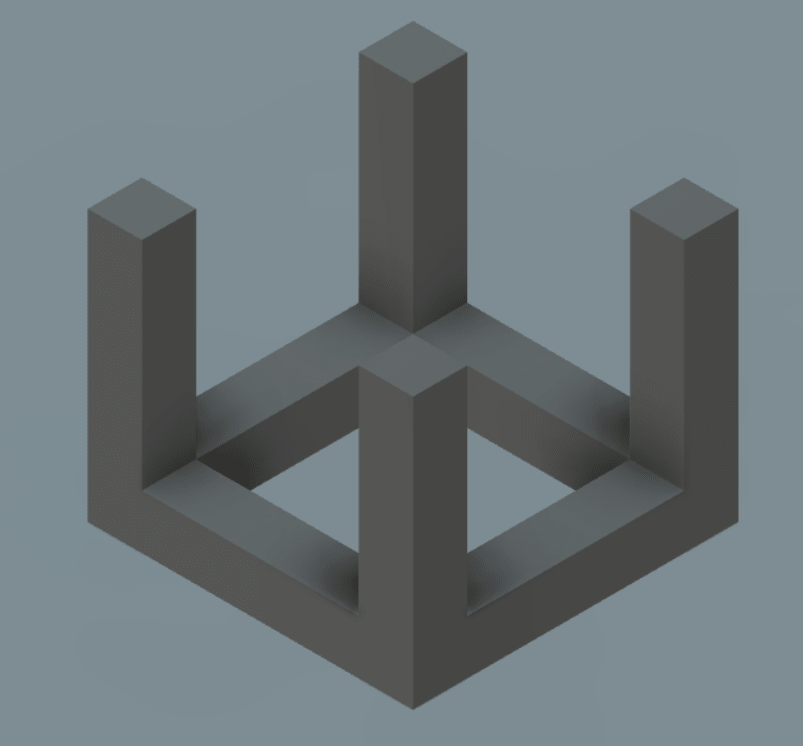
Draw a sketch for four squares
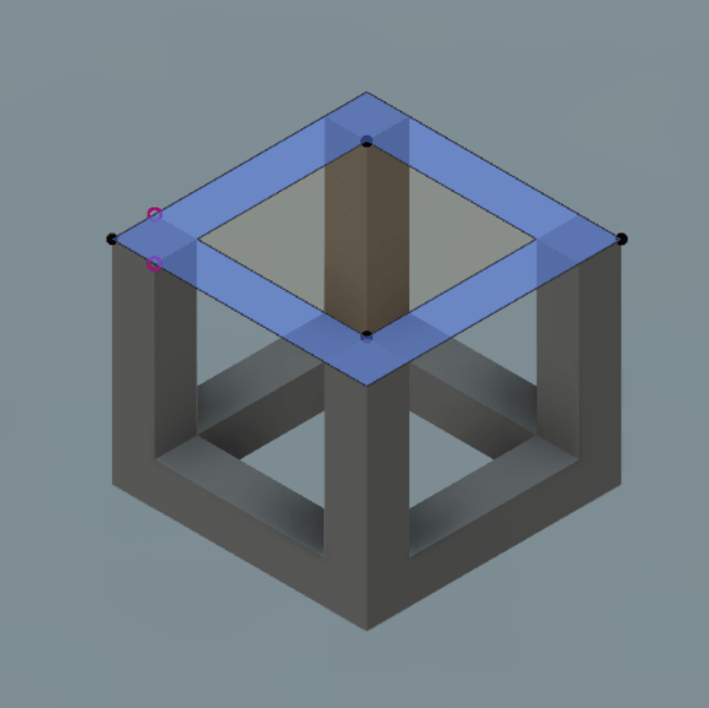
Create plane in the middle distance, then mirror first extrude

Add a sphere in the middle of created plane. And that's it :)
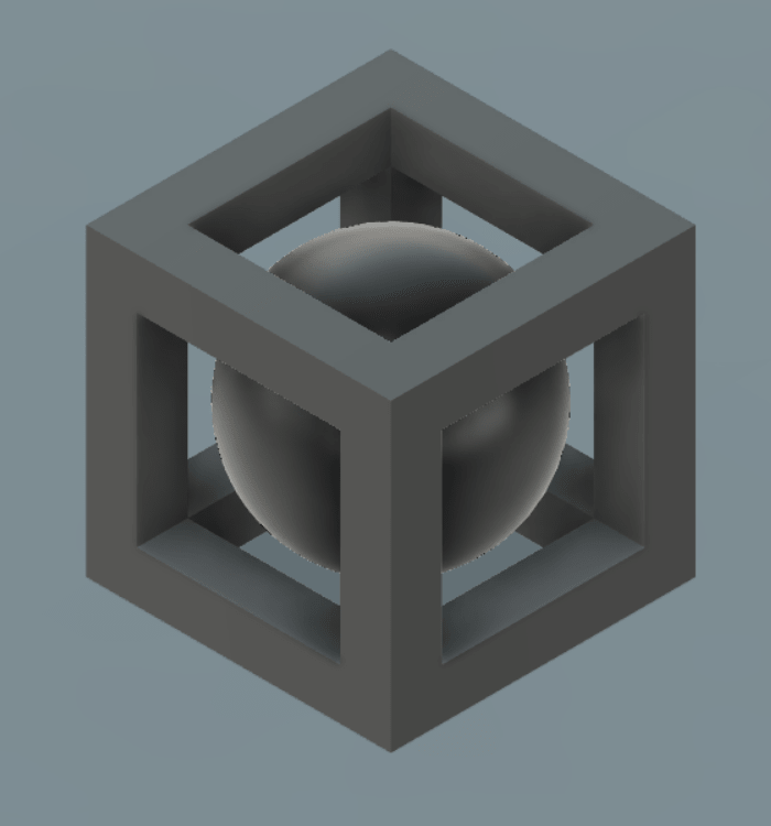
This design can't manufacturing by subtractive technologies because the sphere is inside the cube no cutting tool could enter and machine it without destroyed the cube edges!
After design complete select your object, press make 3D print and select oK to save your design as STL file
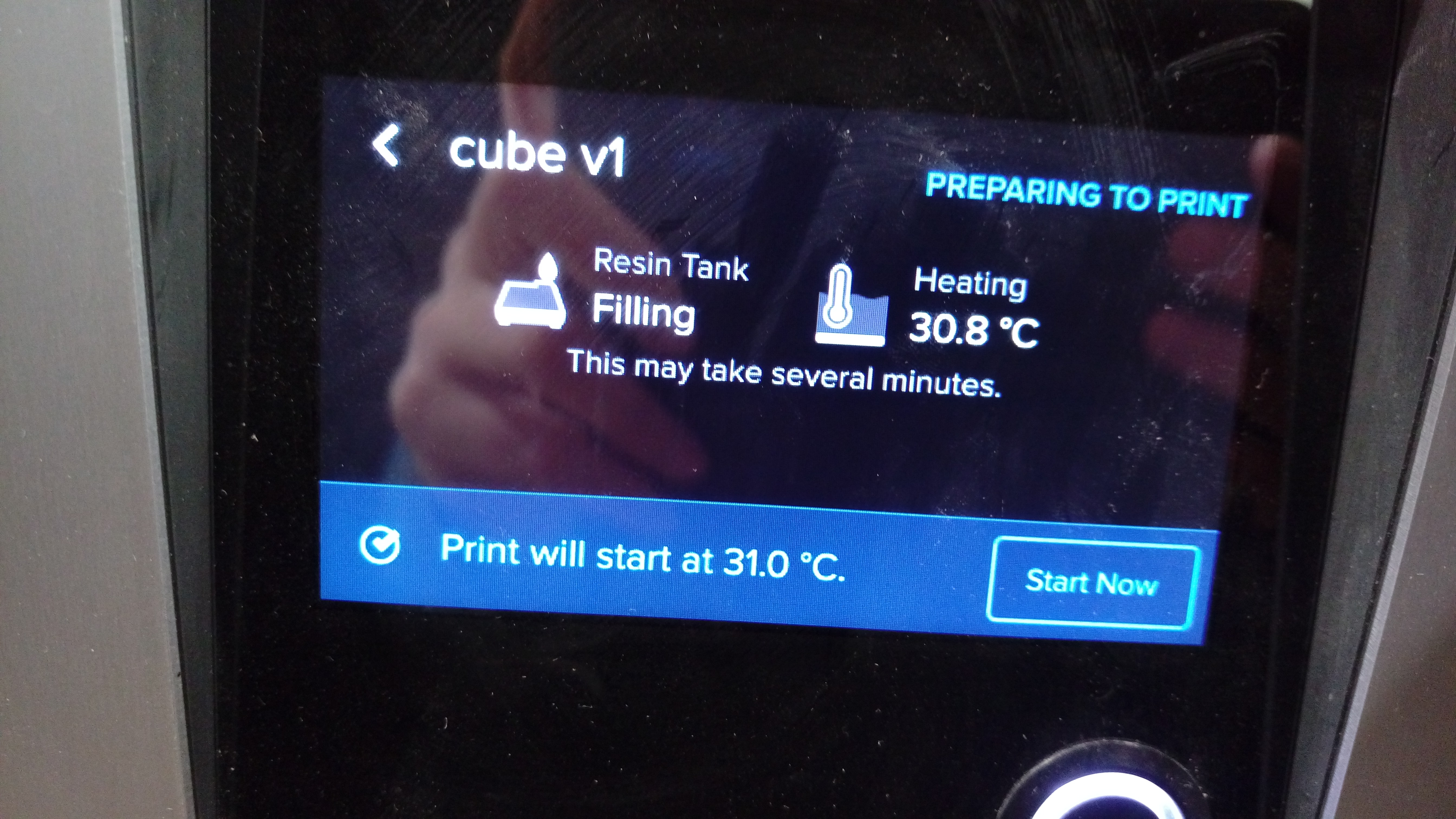
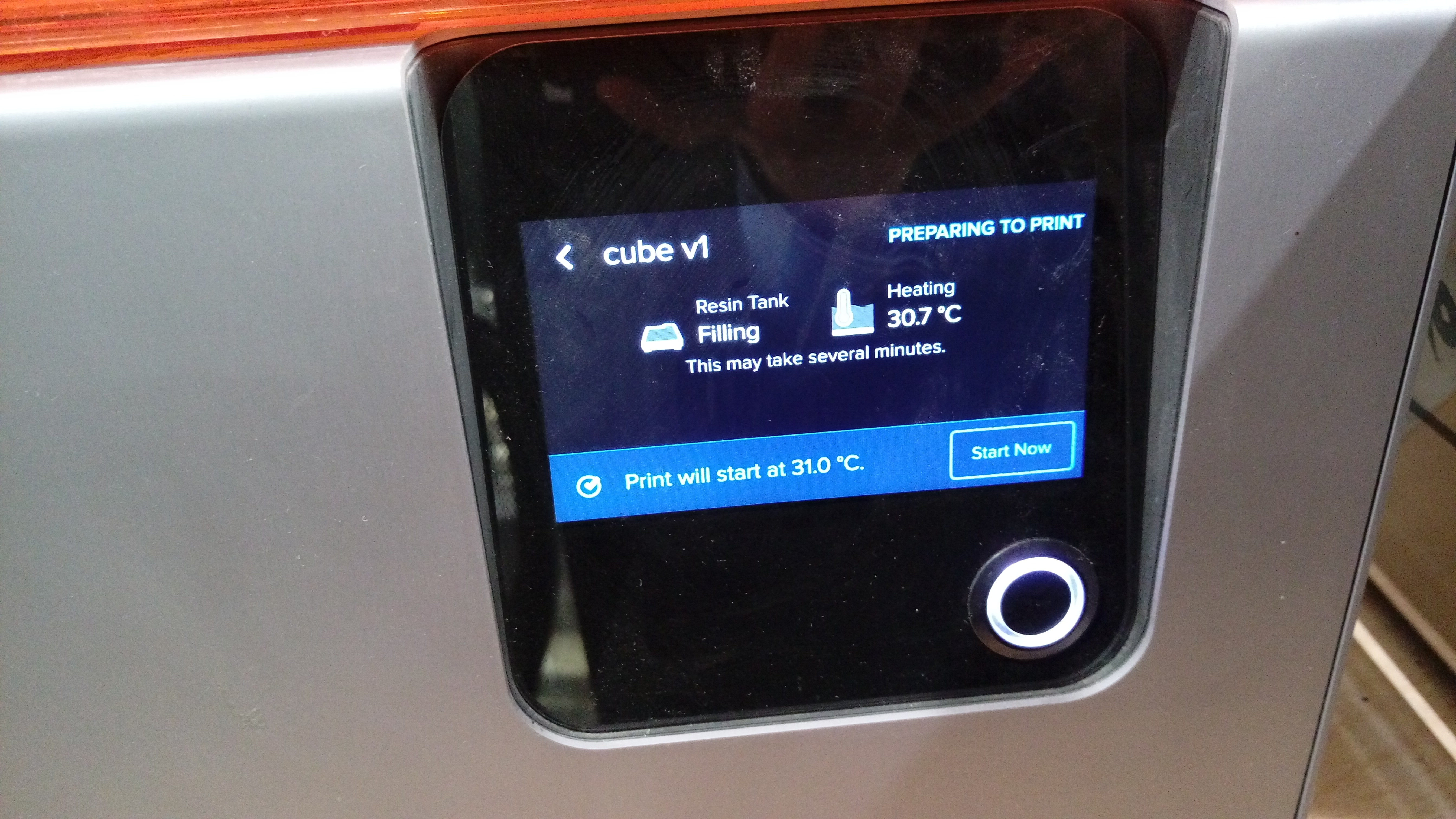
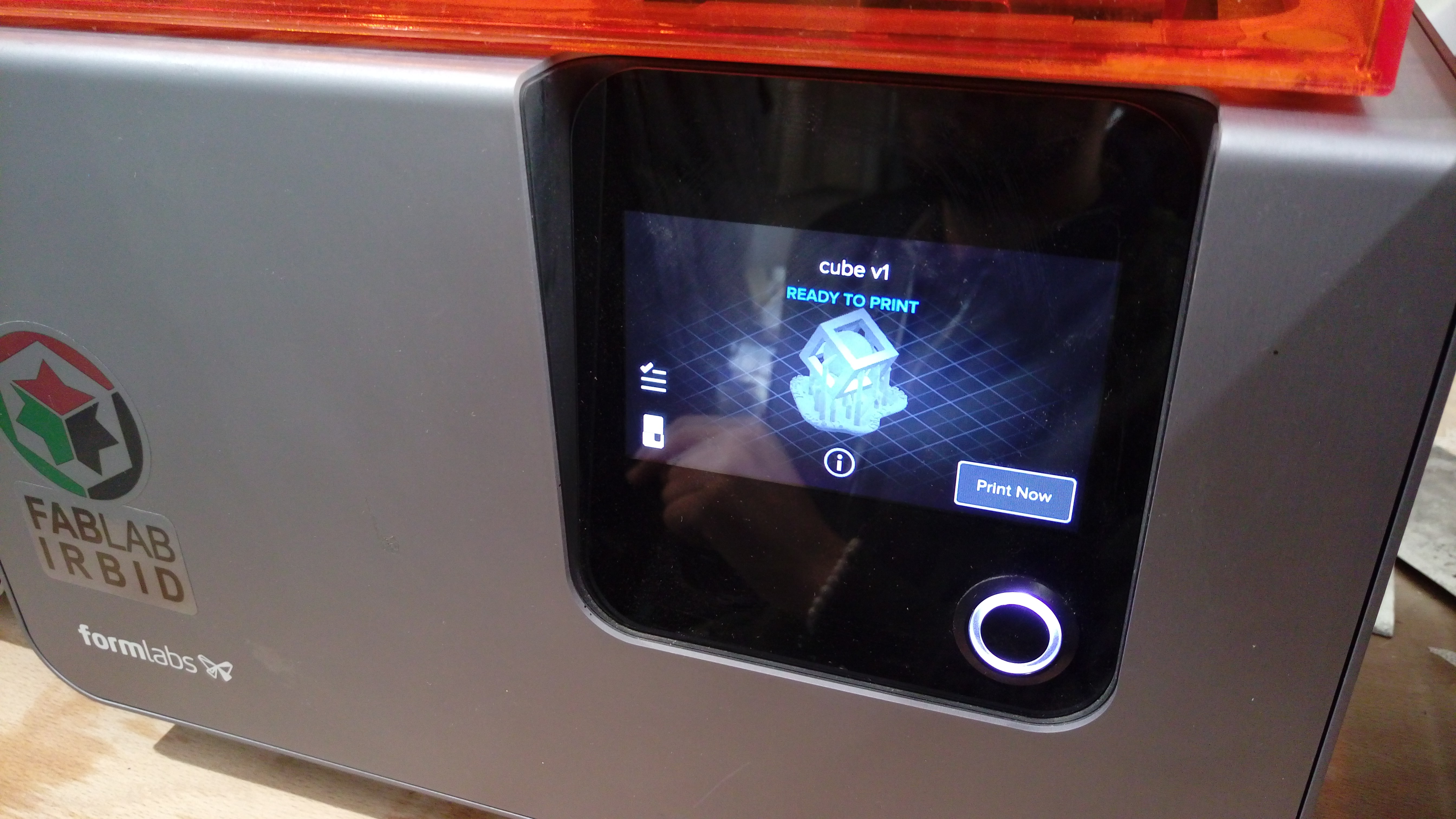
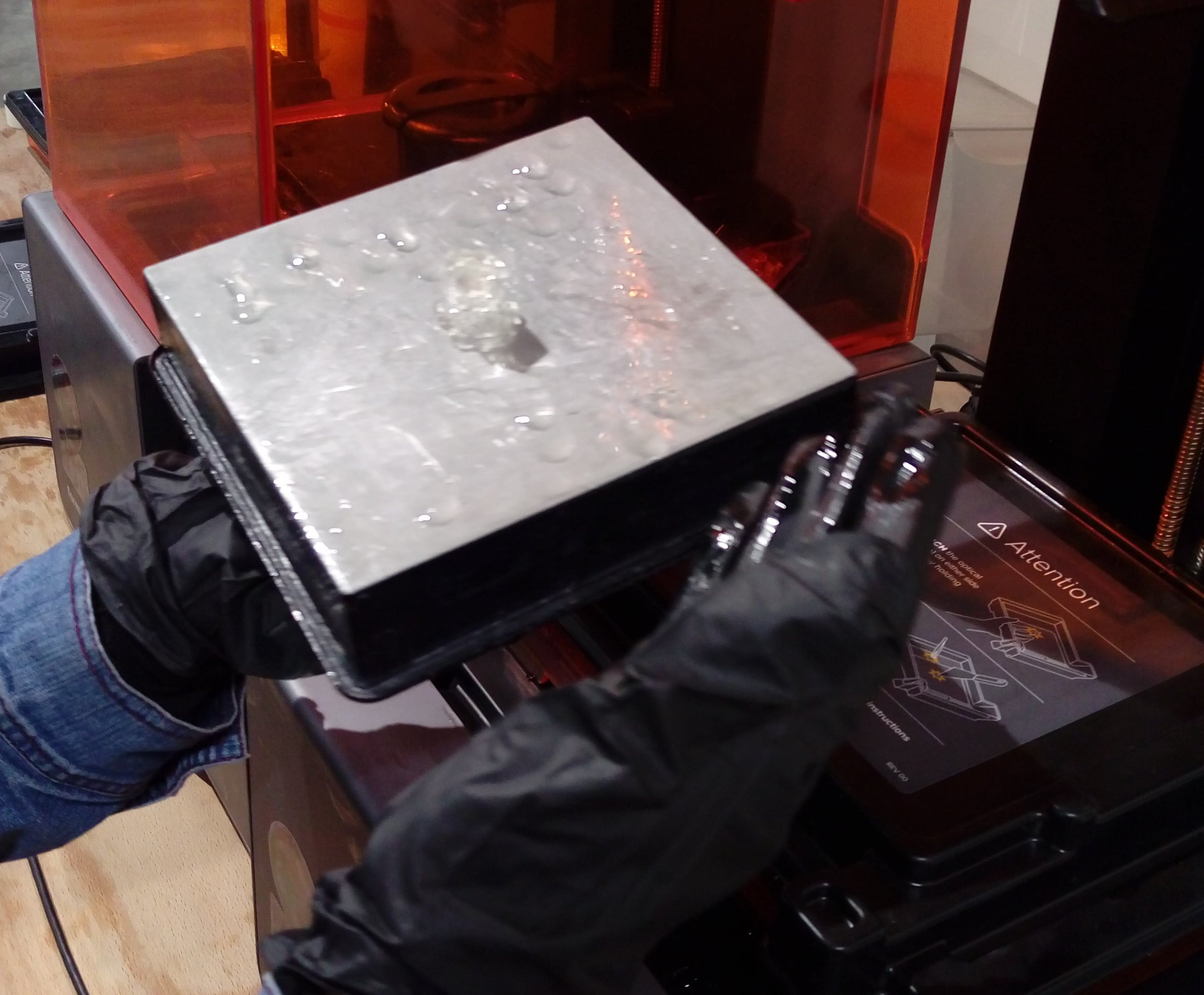
To Print this design I used Form 2 SLA 3D printer from
formlabs. This is an SLA 3D printer.
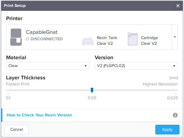
First download Preform software ![]()
When open the program choose printer's name and material color and type, layer thickness, then press Apply as shown:
Open the STL file, at the left side of program screen there is some icons to move and rotate your object and also to control support material.
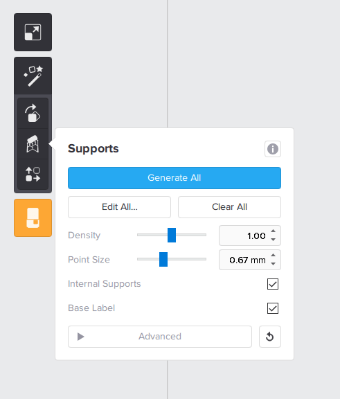
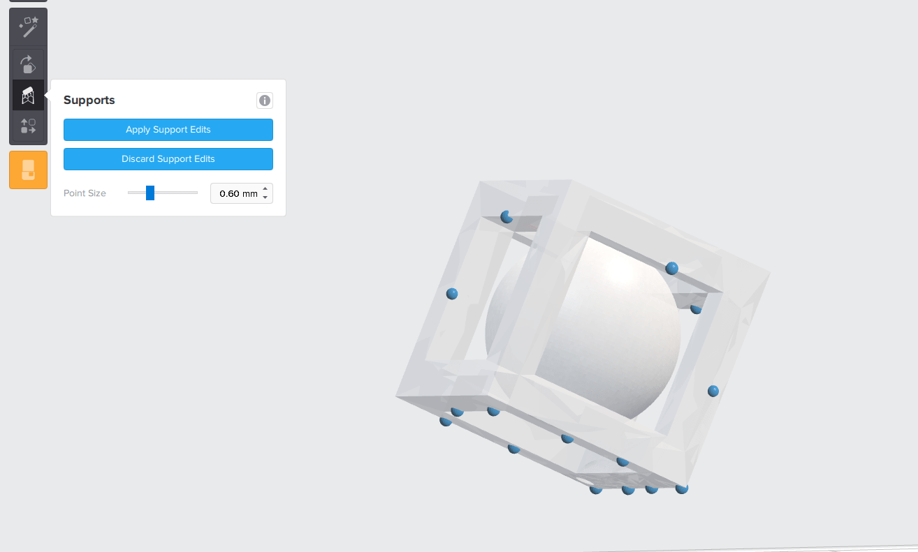
This software has a cool feature which let you detect the point where exactly you want to put support material press Edit All and click at the desired position.
Then save file, connect printer with your laptop using USB cable, printer settings:
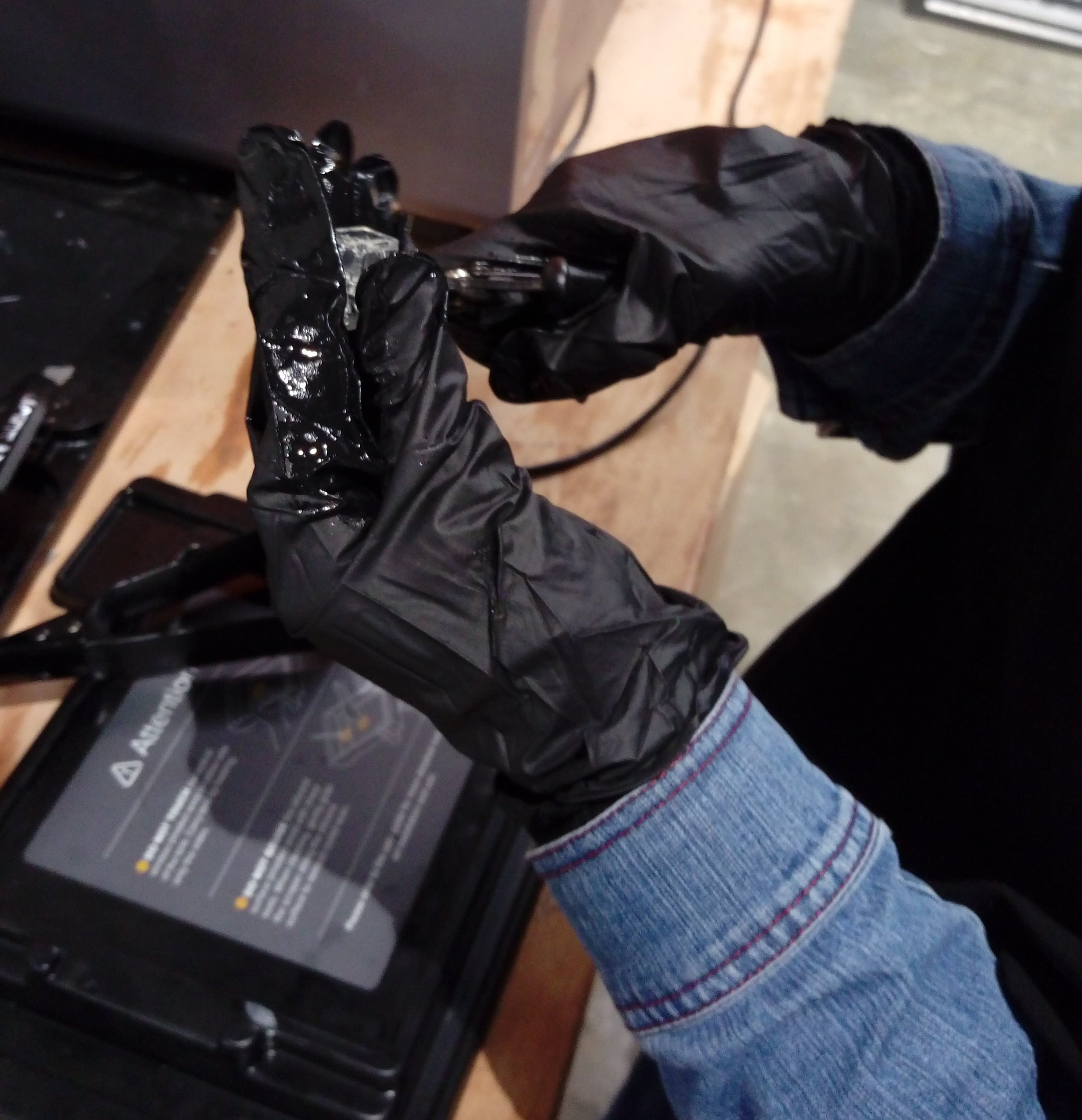
After print complete carfully remove the object and put it into alcohole clean the plate
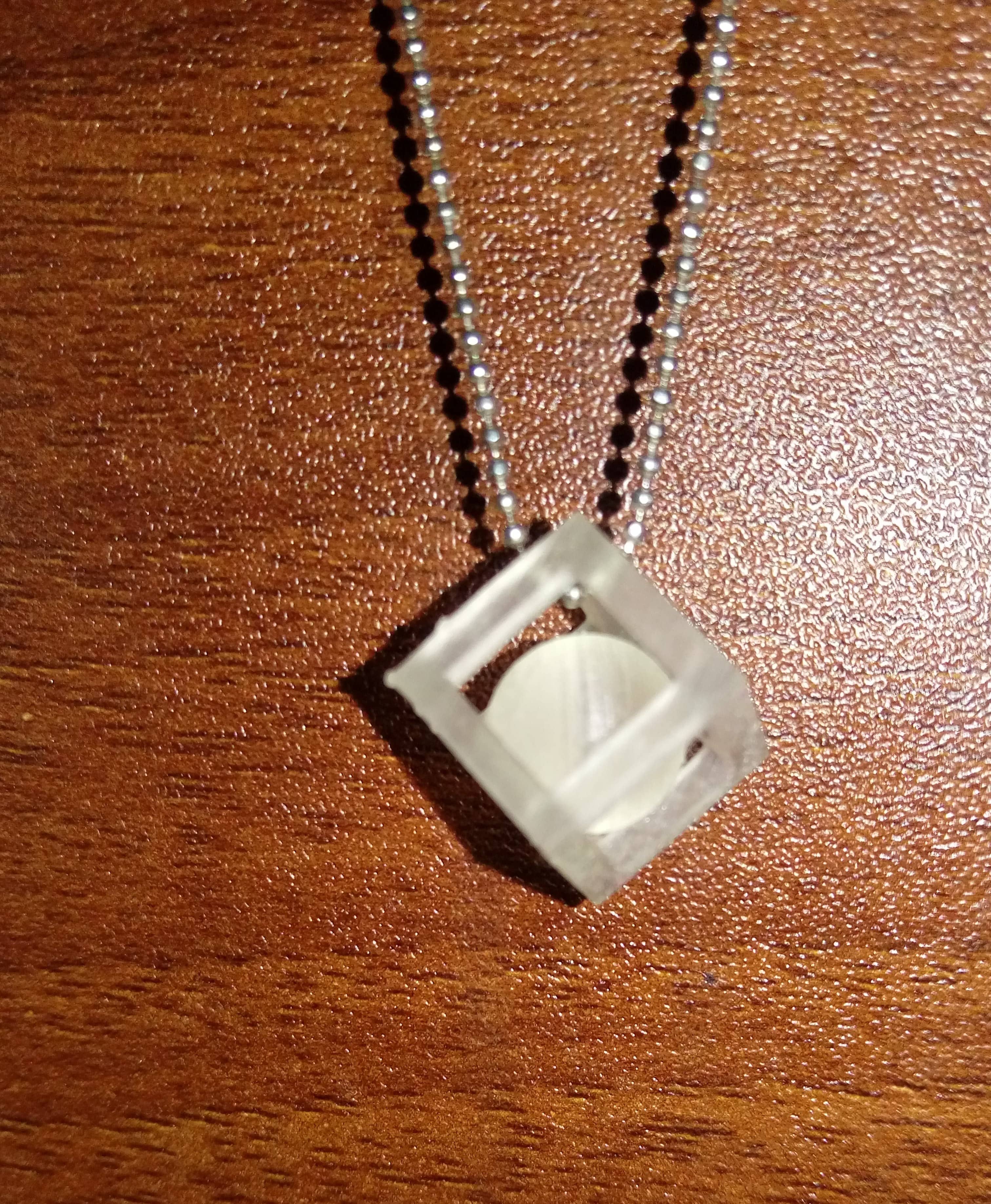
The final result:
This week was a good chance for me to spend time thinking and design for my project. I tried a lot with different ideas, designs and settings. Nothing works from the first time!. But no efforts goes for nothing I learned many things at least to be more patient :)
I will show final success designs, and explain what mistakes I did and why
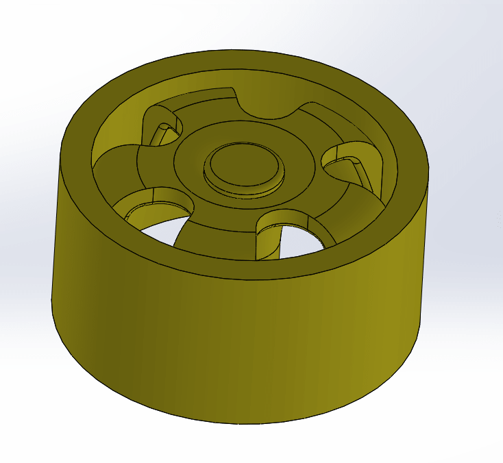
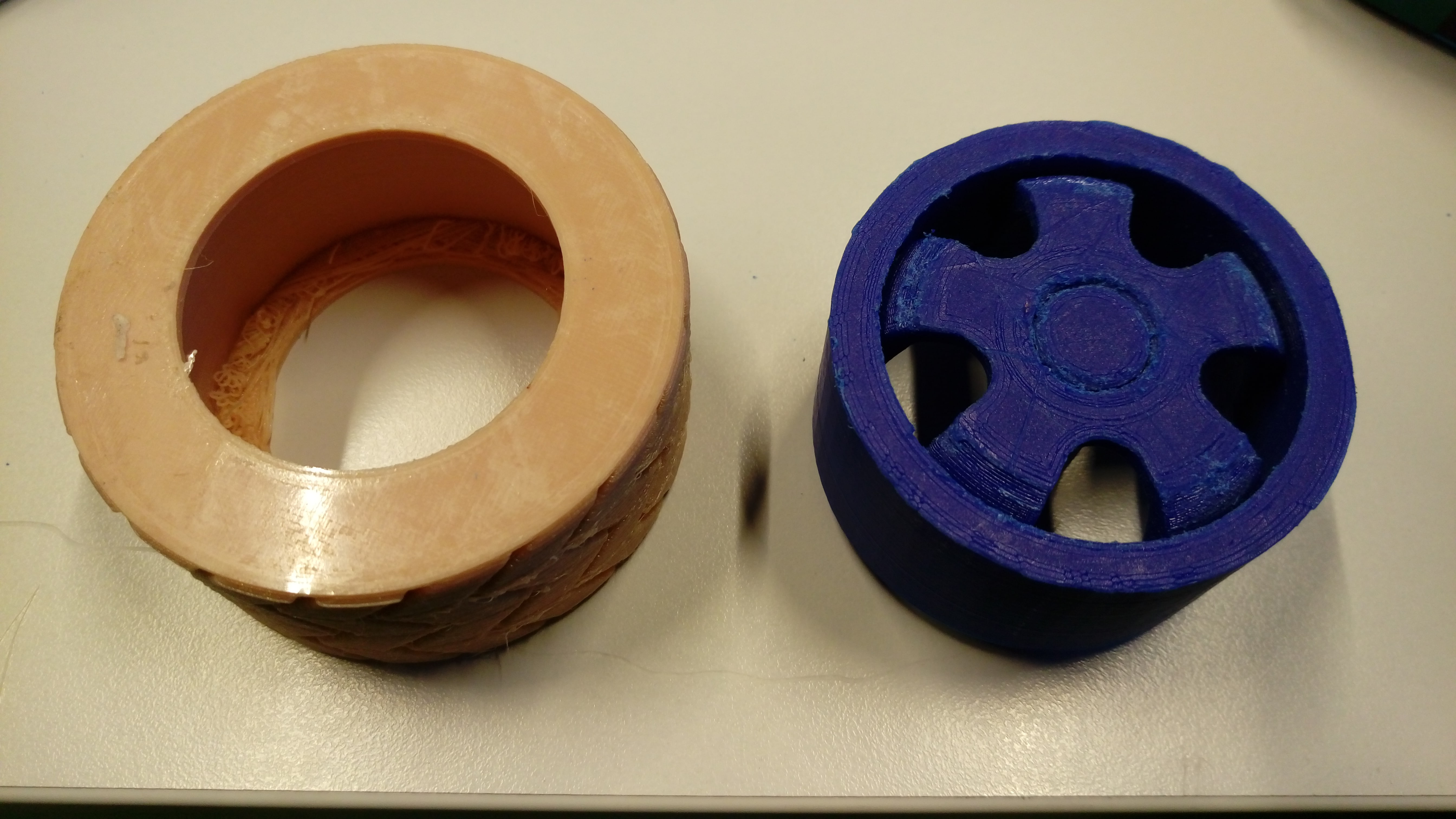
I need four wheels for my final project robot two of them should connect to stepper motors so this will affect the design. The wheel consists of two parts flexible tire and rigid rim .
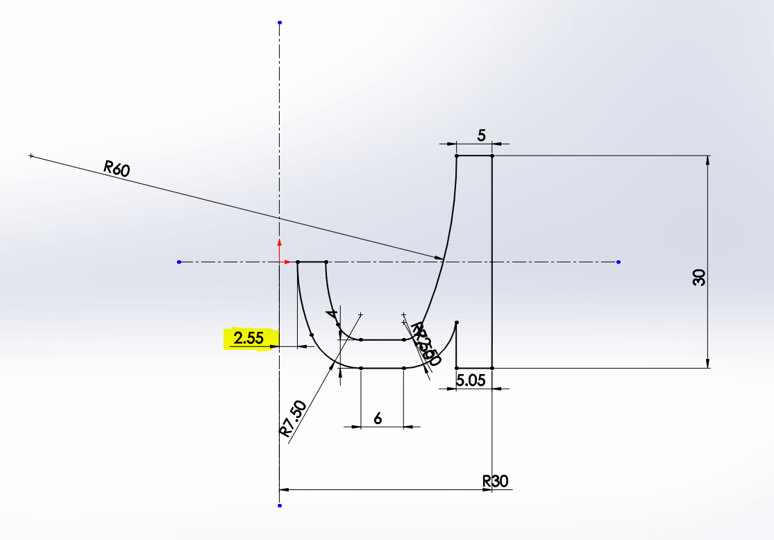
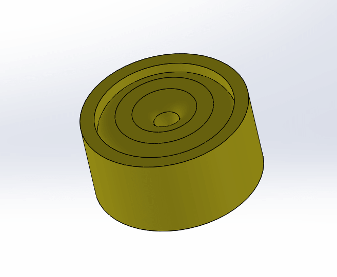
Using SOLIDWORKS ![]() I started to design a rim firstly, I draw a sketch as shown
I started to design a rim firstly, I draw a sketch as shown The shaft of the selected motor Nema 17 has 5mm diameter, so the highlighted dimension should be 2.5 to become after revolve 5mm but after I print it I can't enter the motor shaft into it so here I make it little bigger
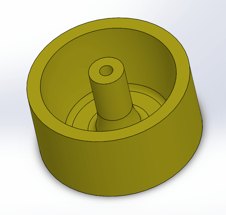
Then make a revolve
Draw two circles and extrude them to become a holder for the motor shaft.
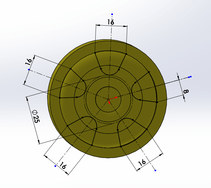
To make holes inside the wheel first draw this sketch, then use Extrude cut feature
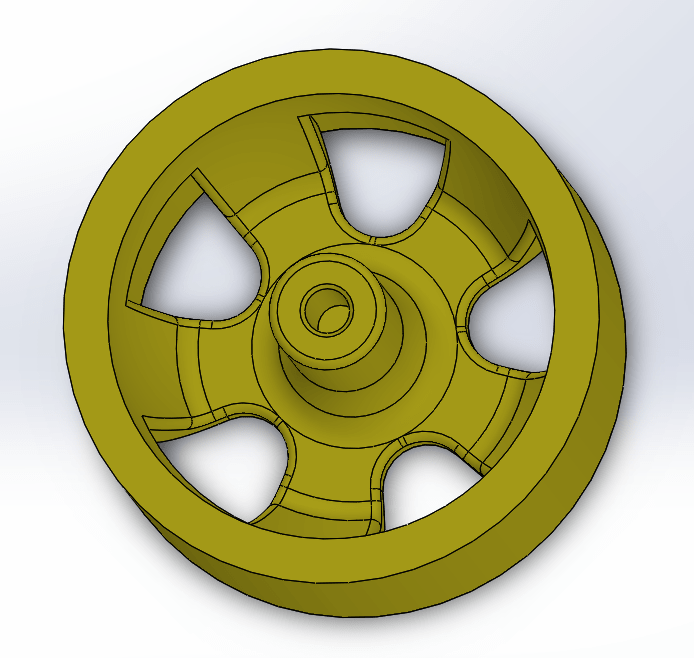
Then add some fillets to make it looks better. the final result is:
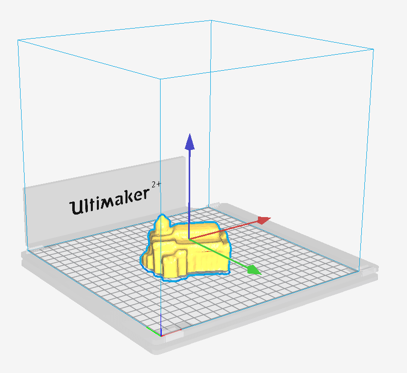
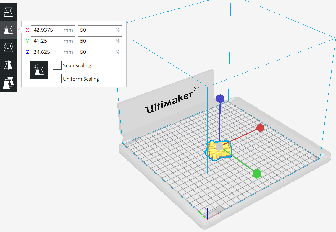
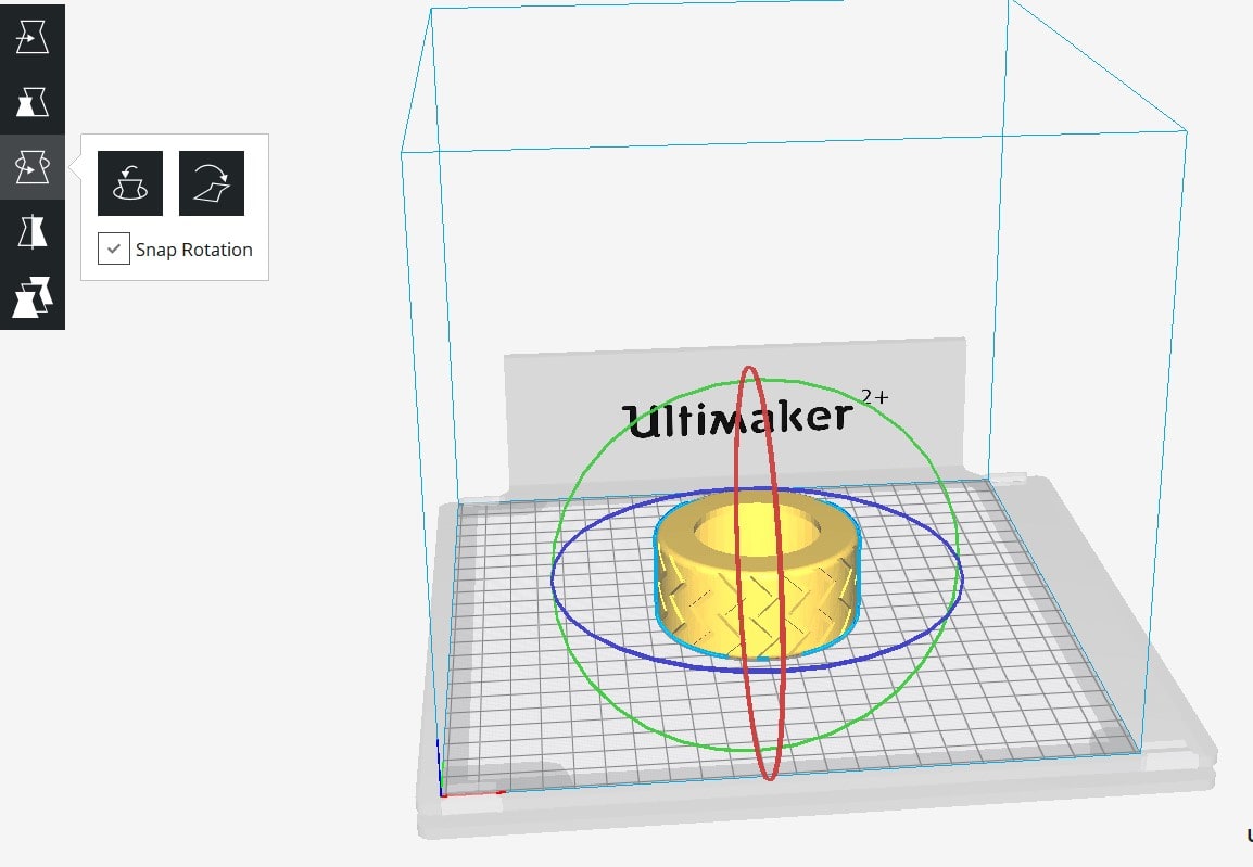
Now save file as .STL and open it by Cura and rotate it as explained in the beginning of using cura.
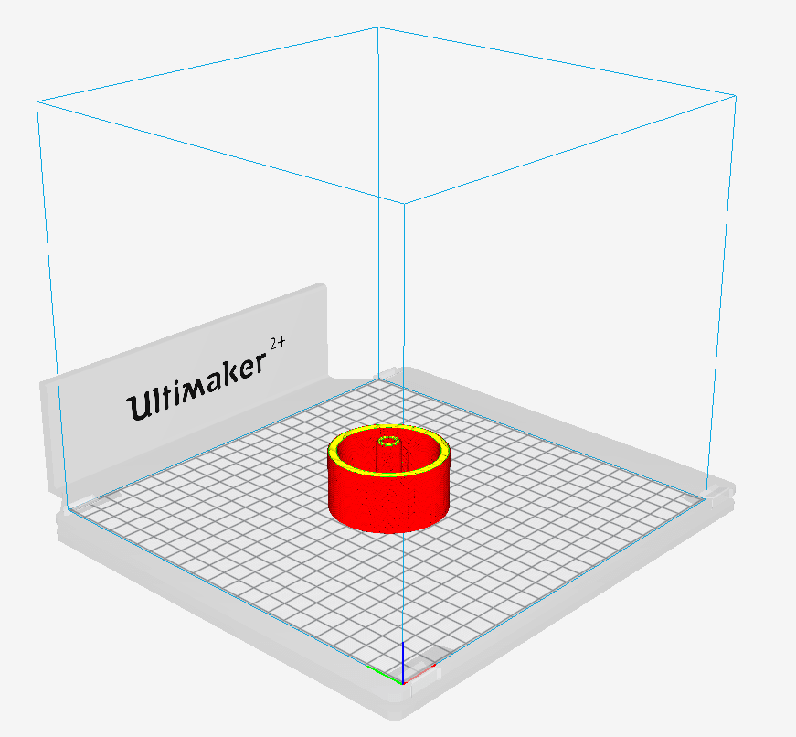
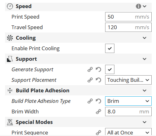
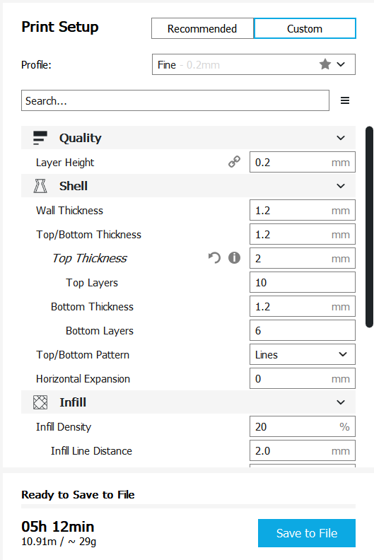
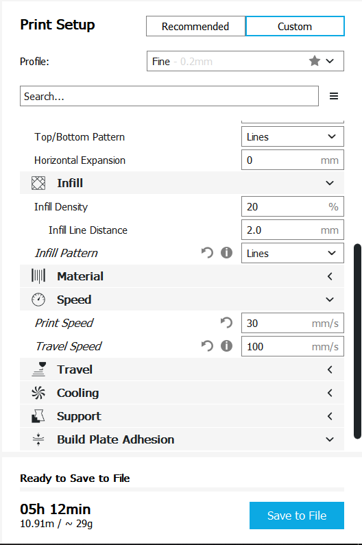
Select Ultimaker 2+ printer and PLA material and choose these settings:
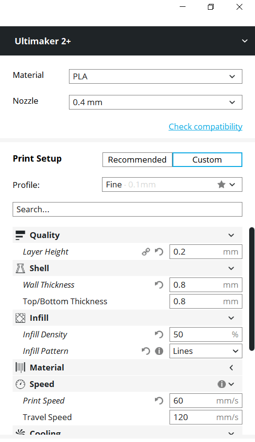
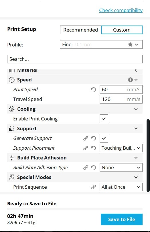
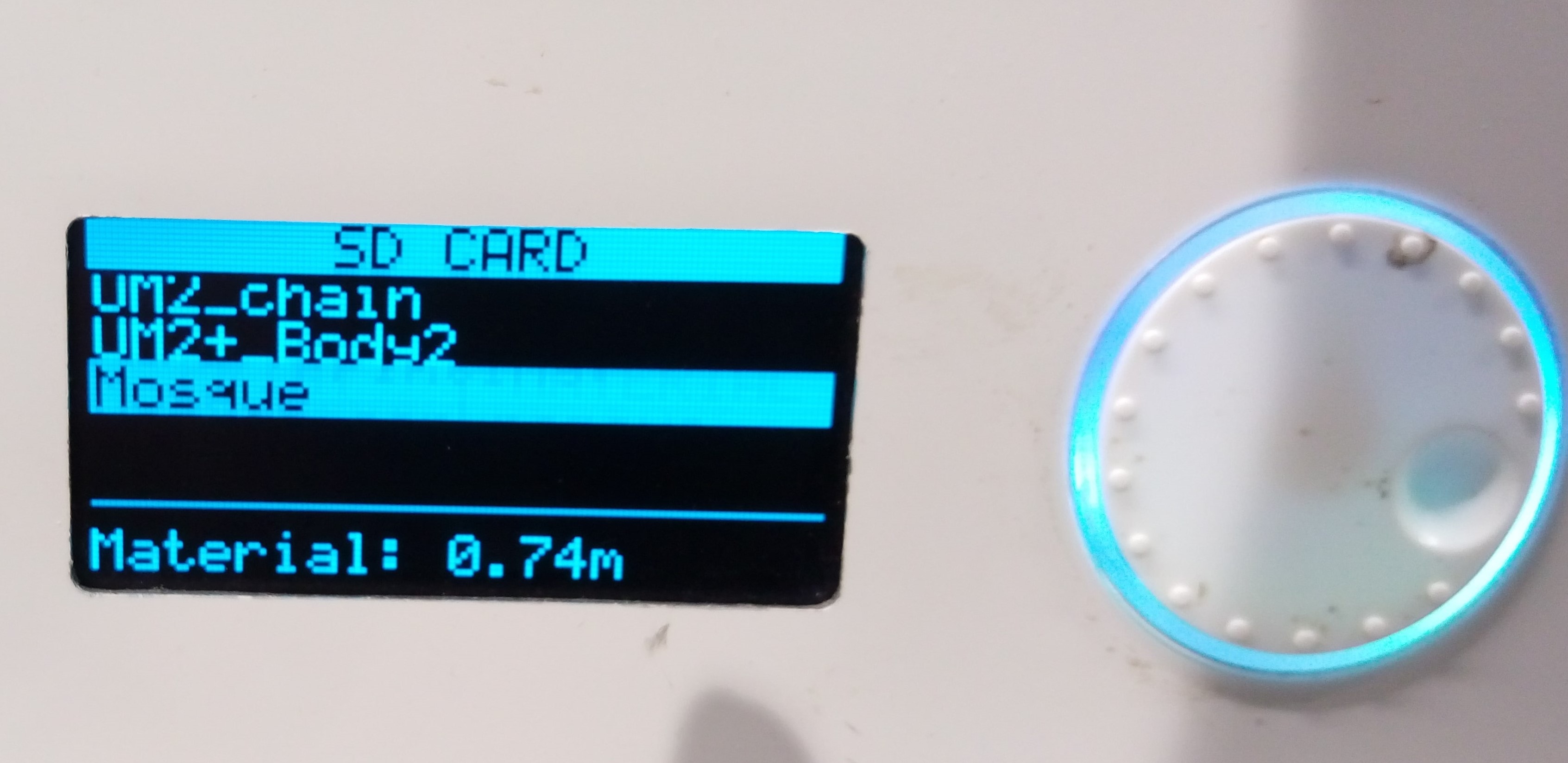
Save file on SD card, make sure that the desired material and color installed in the printer if not, see the explanation of change material above
.
If everything is ok, just plug the SD and select Print from printer's screen and enjoy!
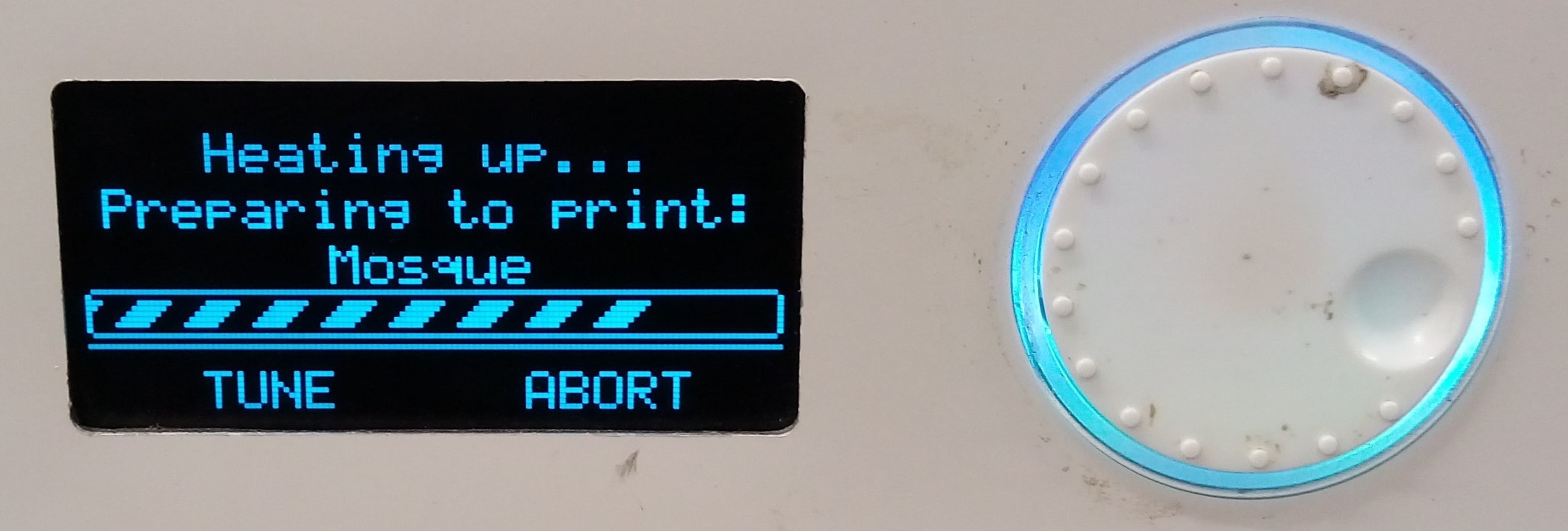
While processing
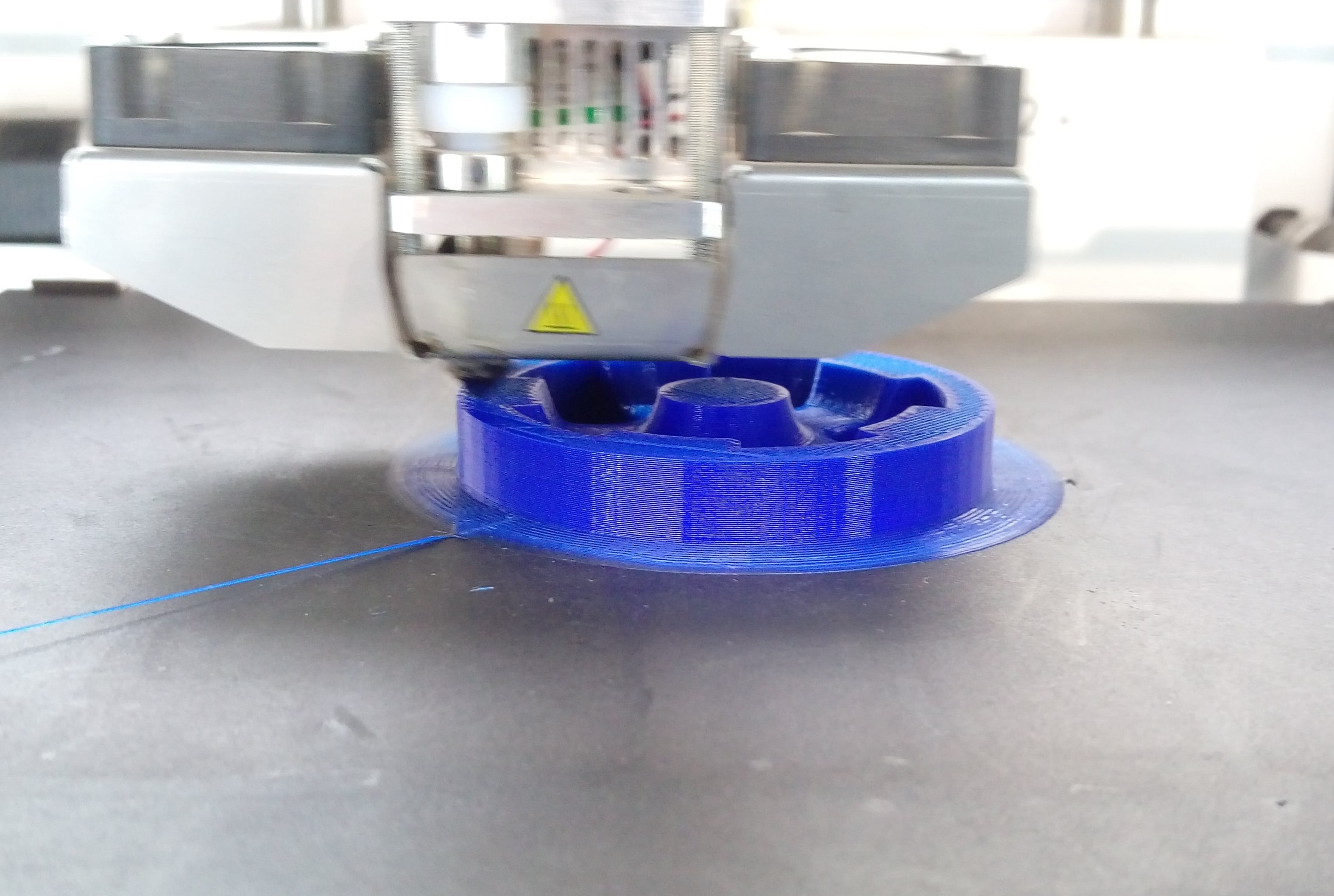
When printing complete
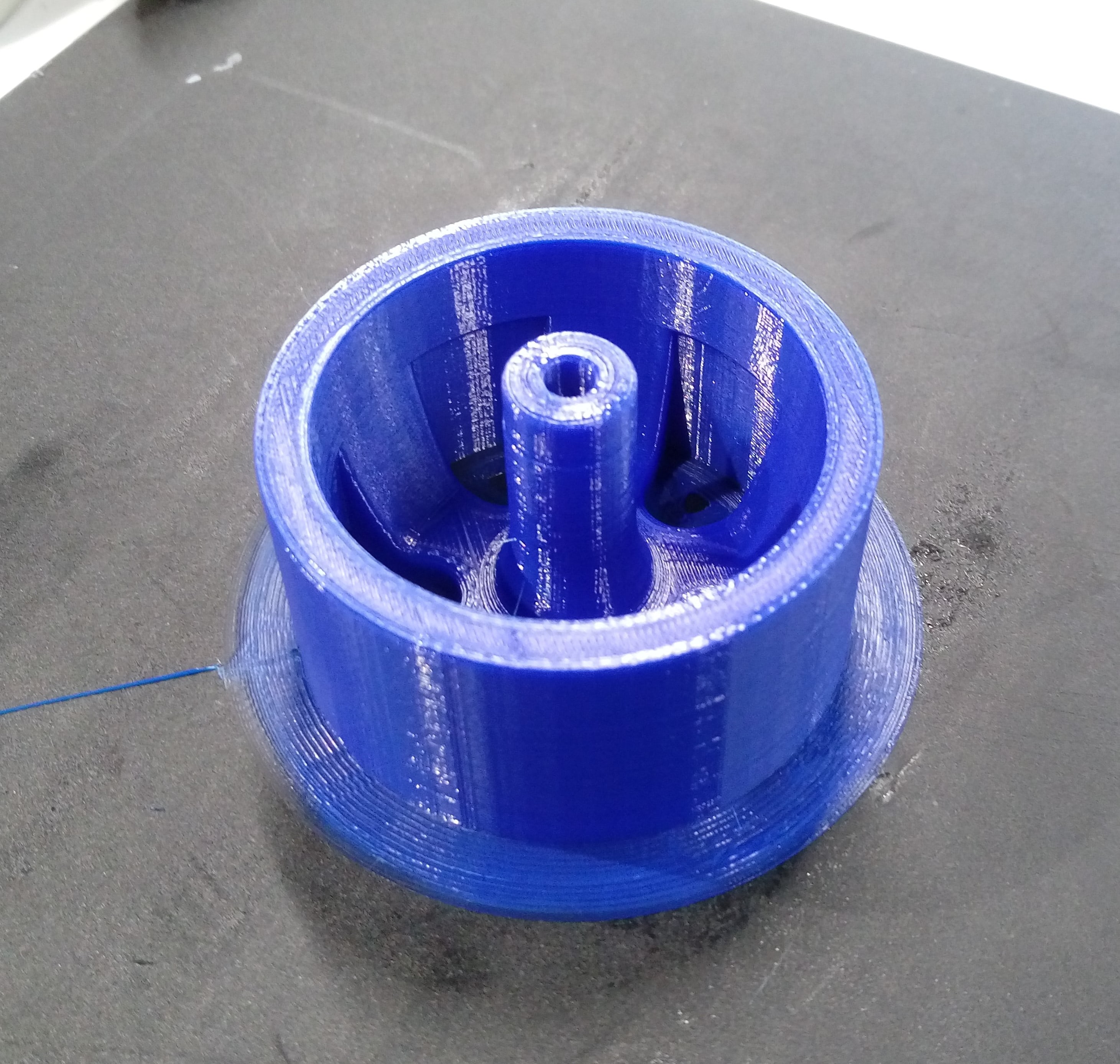
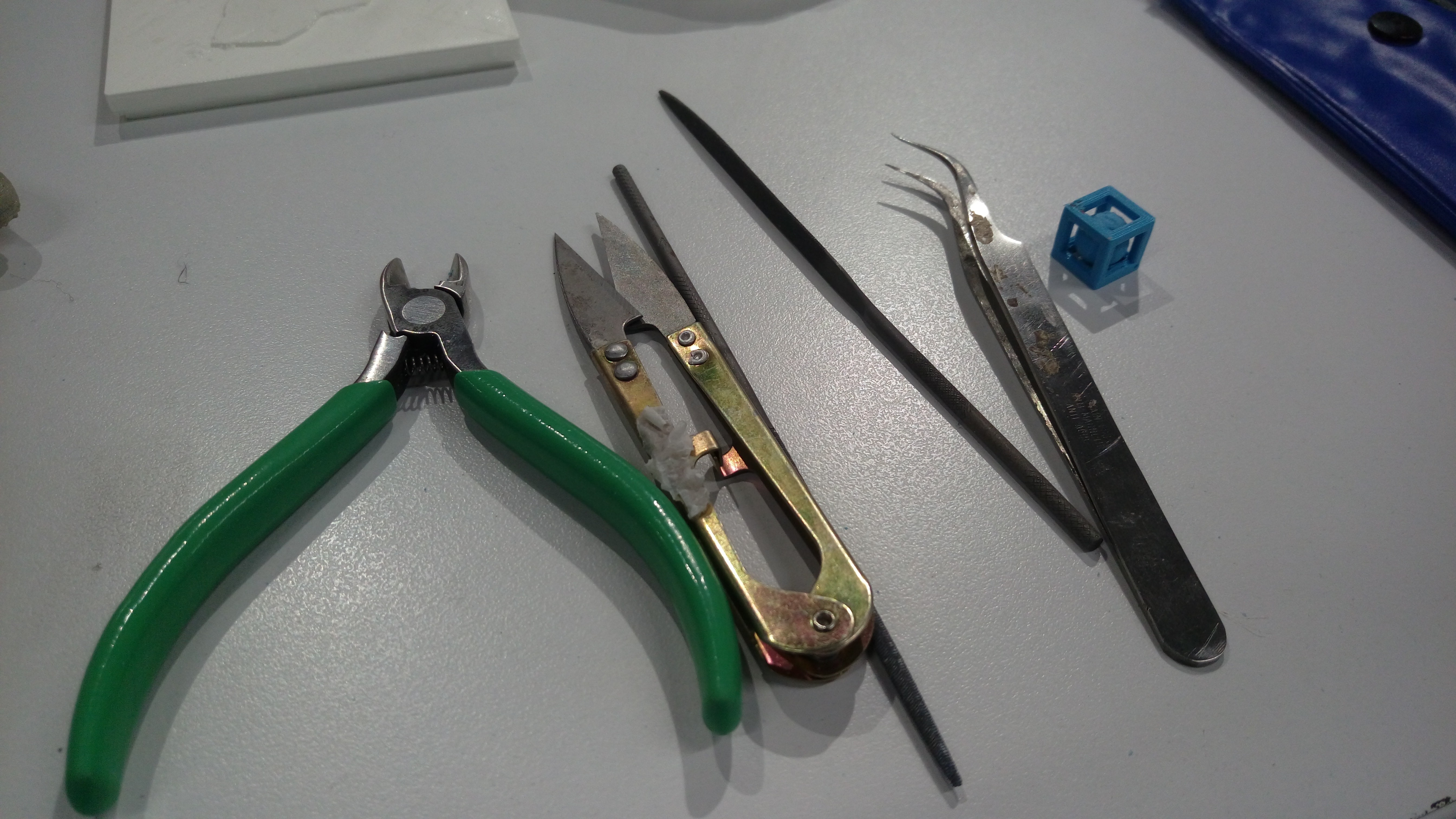
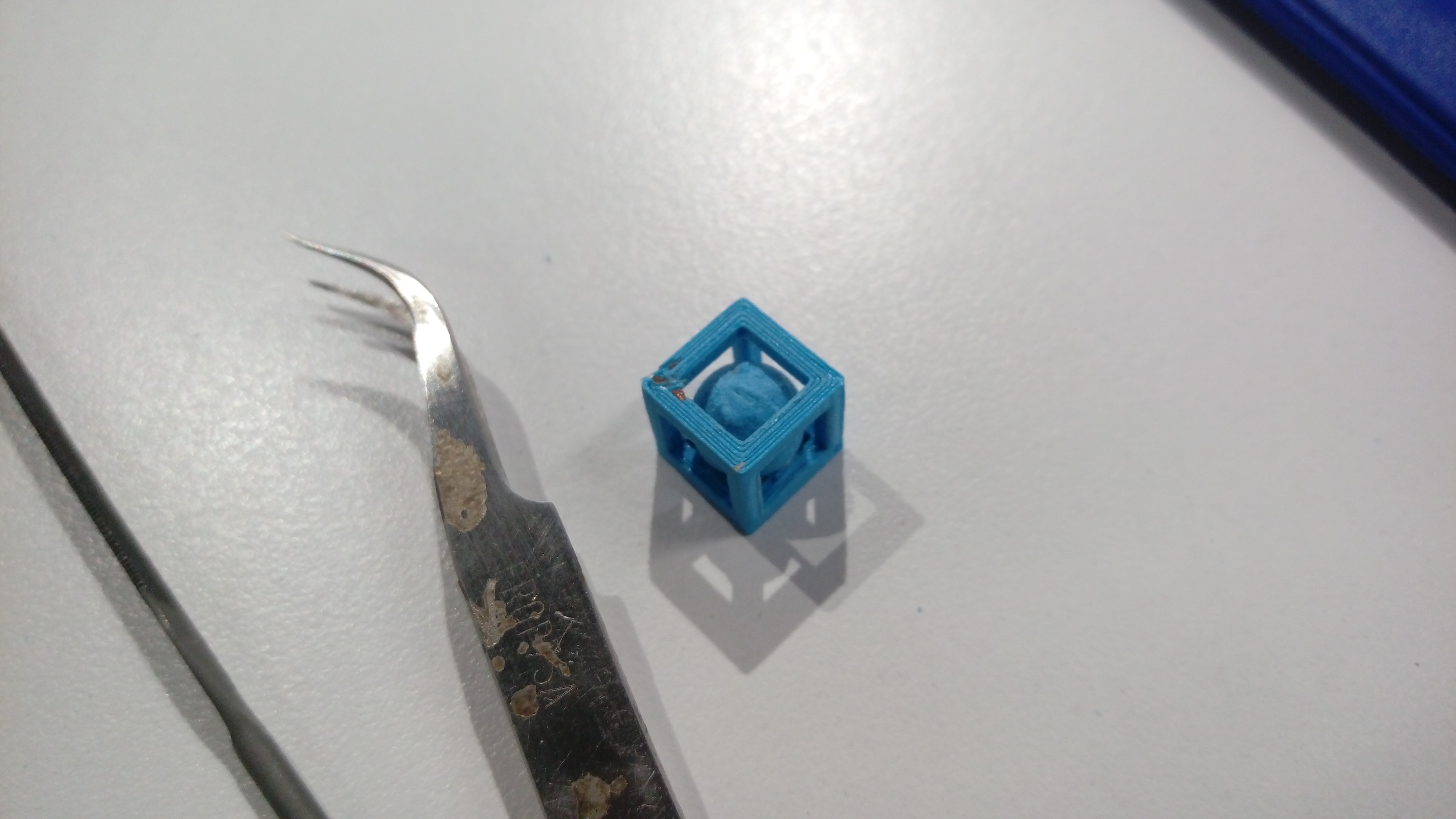
After hardly removing support material manually as shown with PLA cube
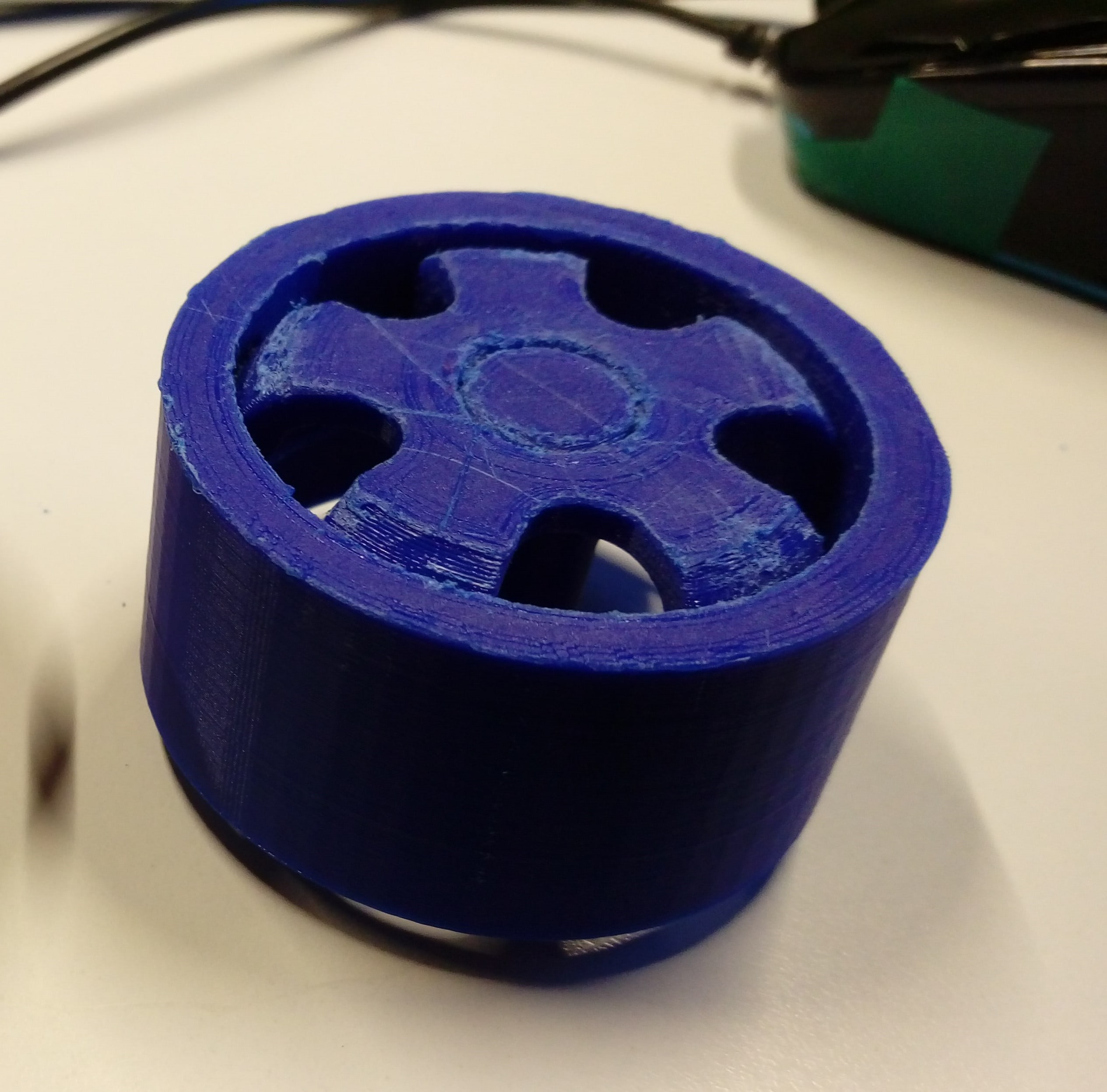
As I mentioned before, when I print the hole exactly 5mm I can't plug motor shafts in so to solve this problem I asked the supervisor of metal workshop Eng. Moath to help me, so he used milling manual machine with 5mm drilling tool and make the hole little bit larger so it is fit now as shown:
The same steps of the rim should be repeated to design and print the tire. Start with this sketch and revolve it:
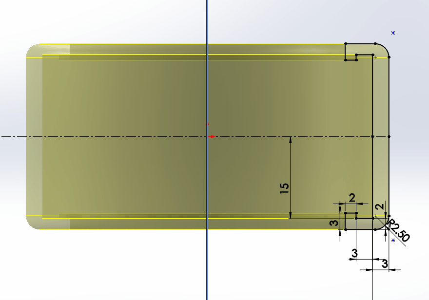
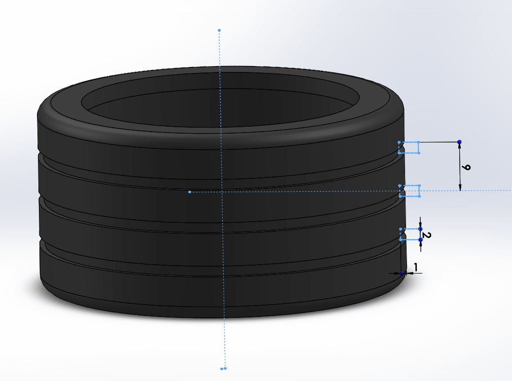
To make slots into the tire draw this sketch and revolve it
Creat a Plane on the edge of the tire and draw this sketch on it
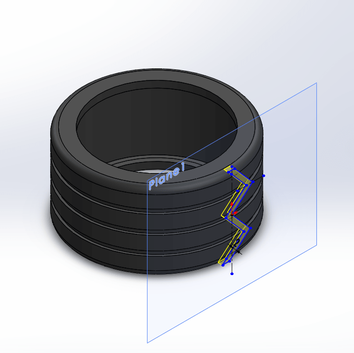
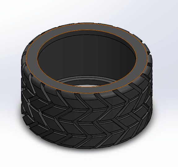
Revlove the last sketch and the final design looks like:
Save design as STL, Move to cura do the same steps done for rim to adjust the wheel position and orientation .
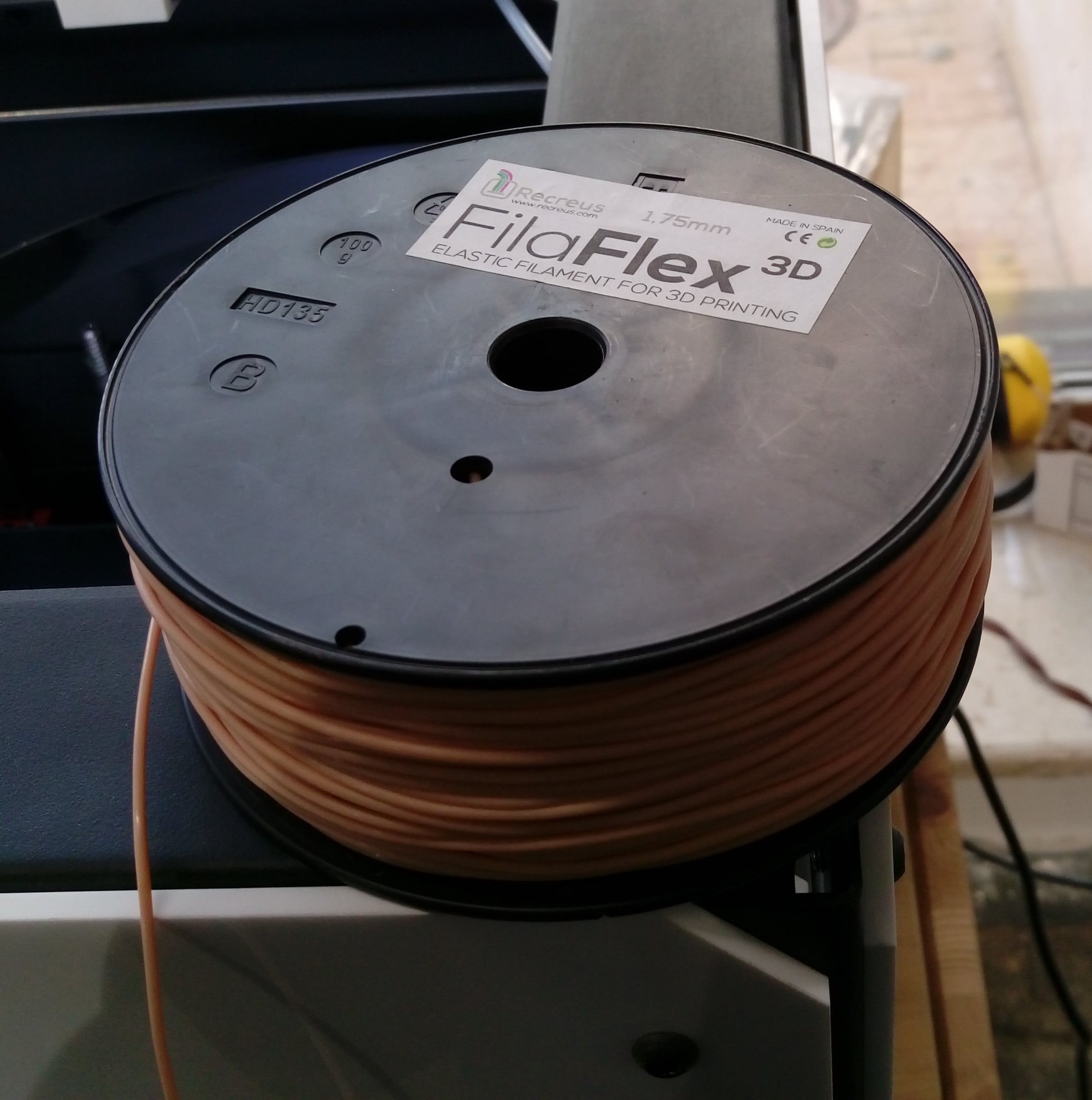
The tire must be flixble like rubber, so can't be print with PLA. I used another flexible material called FilaFlex 3D
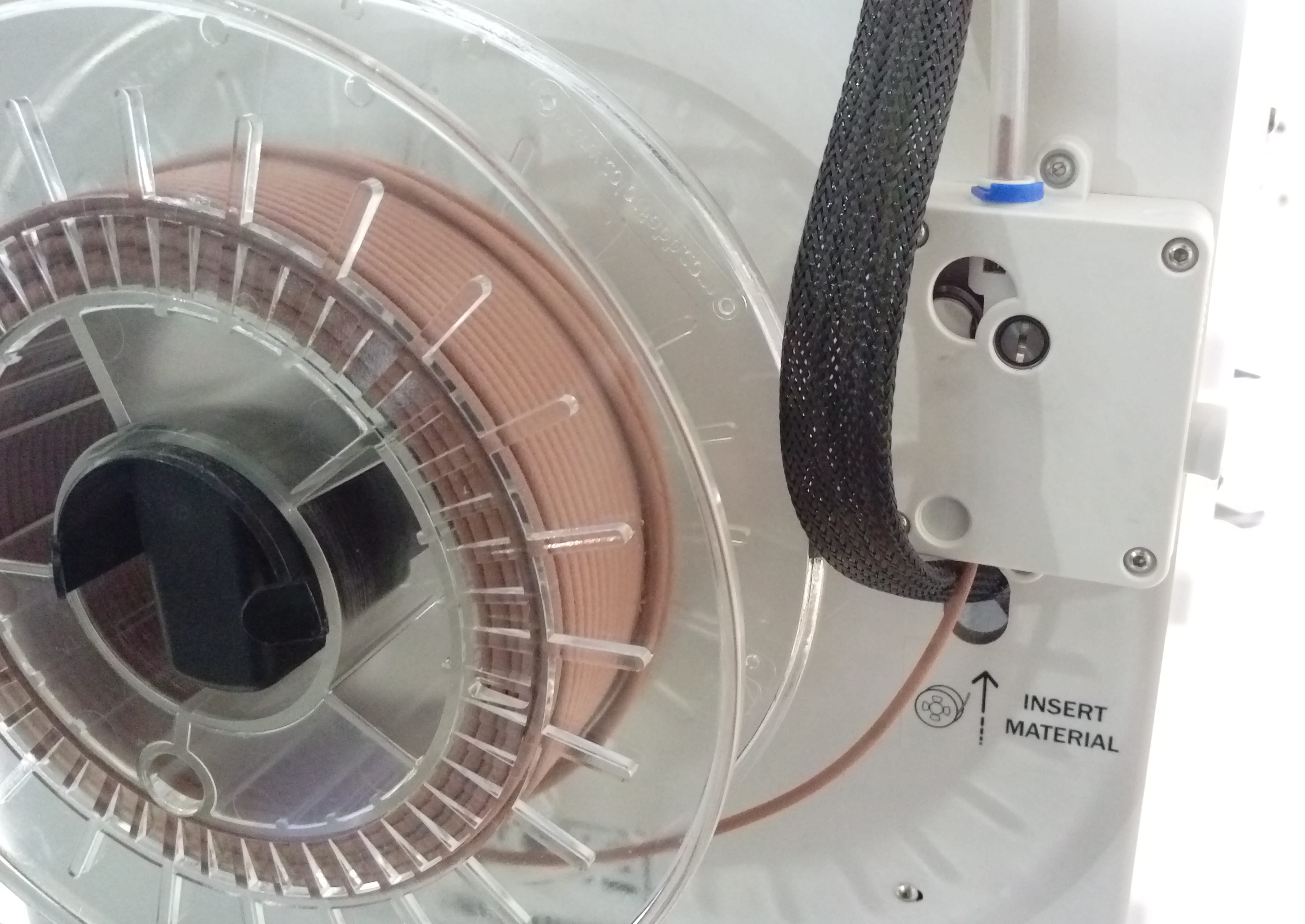
In our lab they uesd Witbox 2 3D printer to print flexible materials because the extruder motor near the nozzle not like Ultimaker extruder motor which is near the roll
. So it is easly pull the material and extrude it.
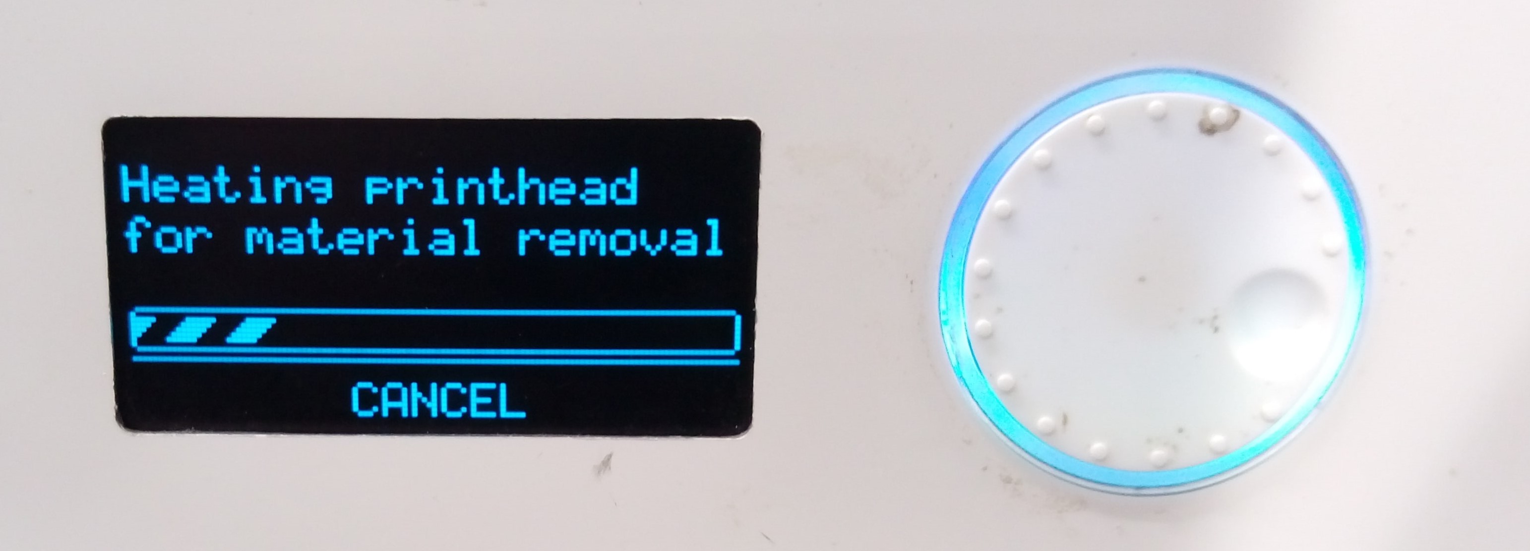
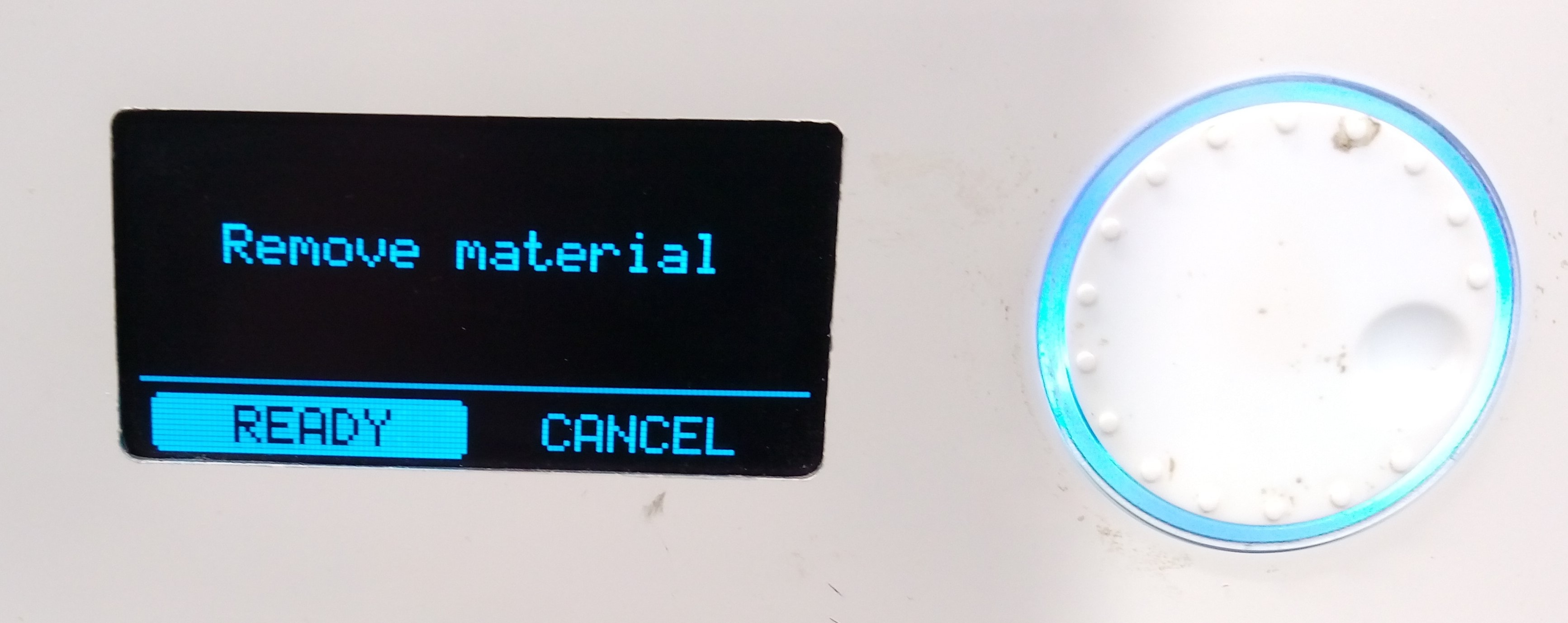
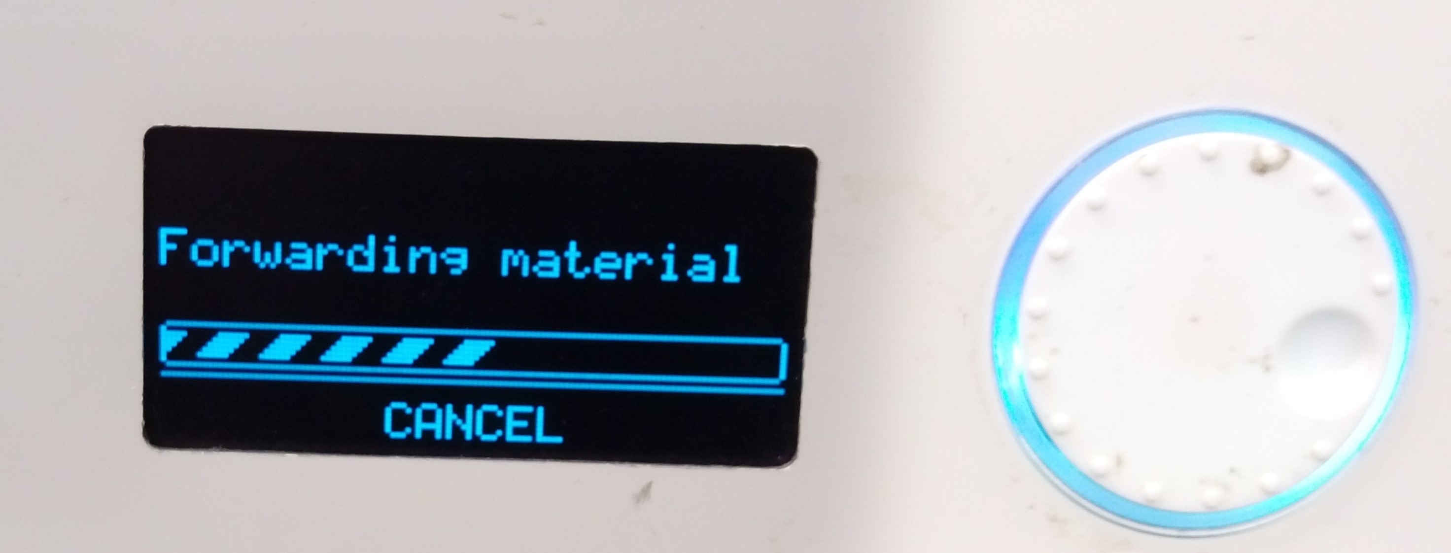
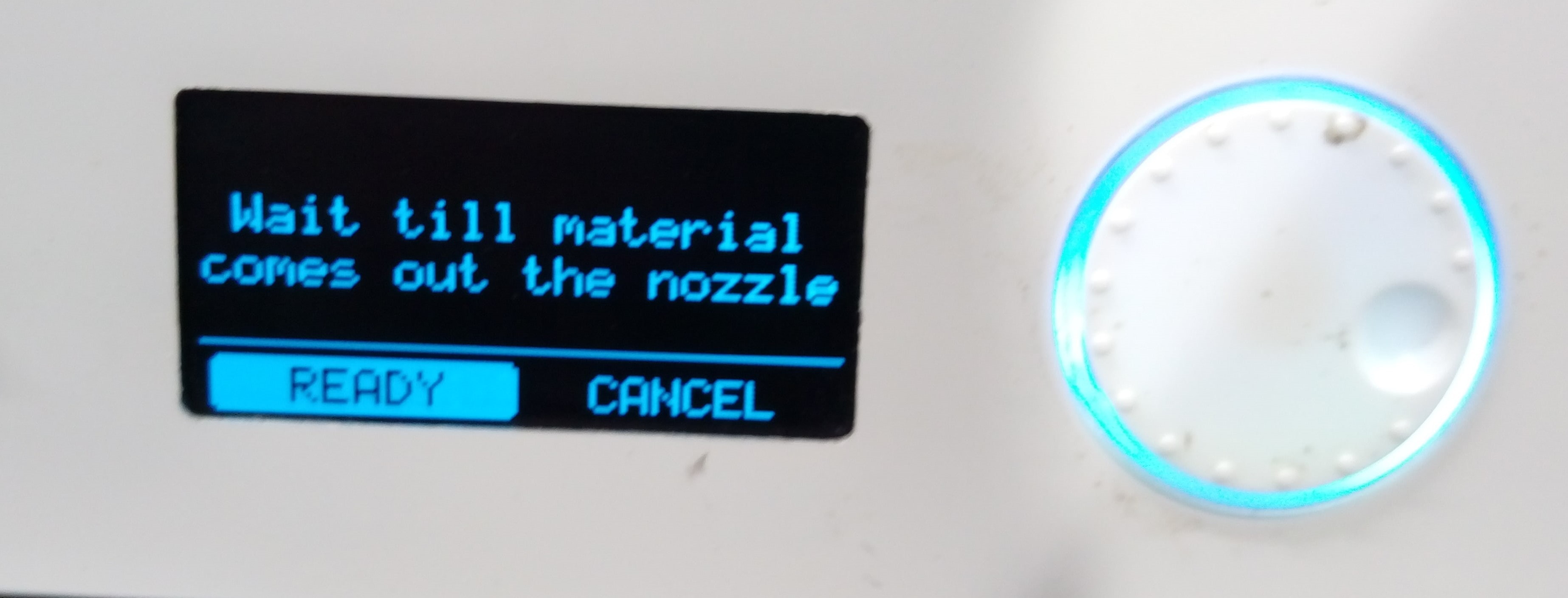
To setup Witbox 2 printer first remove existing material
The first try failed because the design has a parts need support and I didn't but because it is hard to remove support from flexible materials
After many tries I finaly did it. These are the final correct Witbox 2 settings:
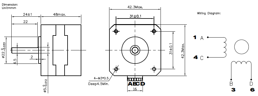
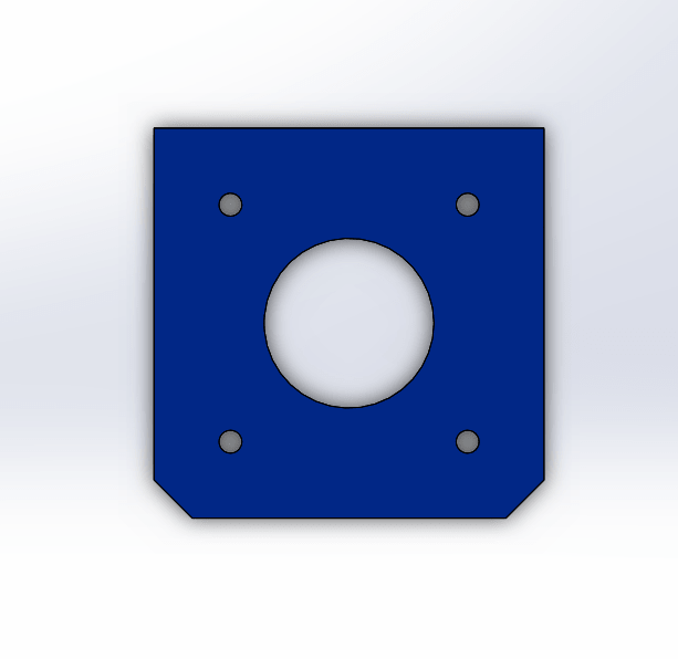
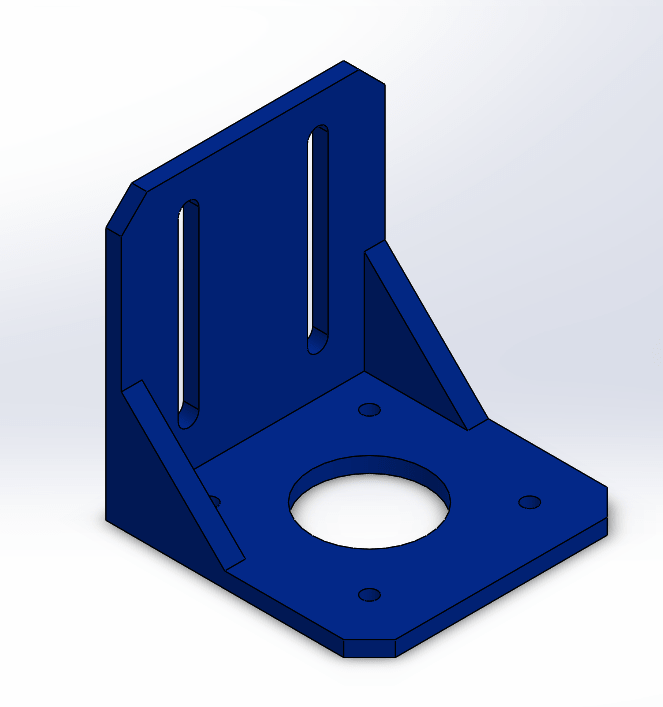
In order to fix stepper motor with robot base I should design a holder for it. I started drawing my first sketch based on motor's dimensions shown below:
Then I extrude the sketch and added perpendicular side with slots to fix the holder to the base using M4 screws and nuts.
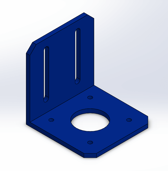
After that I used ![]() feature to add strength to the structure. This is how final design look:
feature to add strength to the structure. This is how final design look:
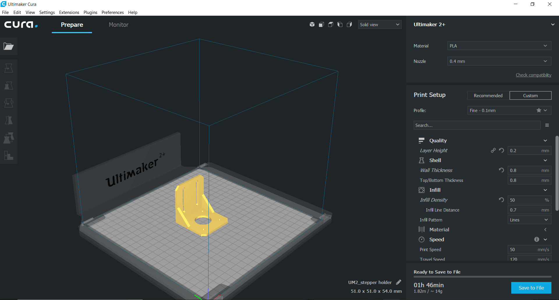
I used these settings in Cura to print the holder:
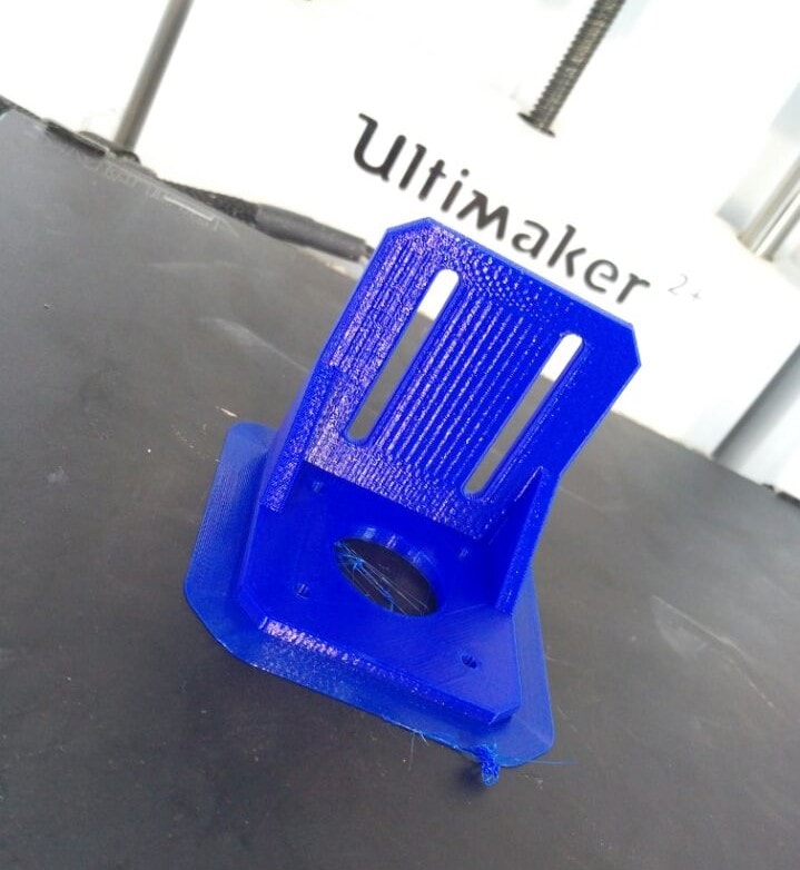
The final result after print completed :
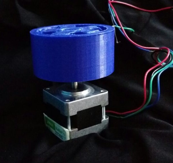
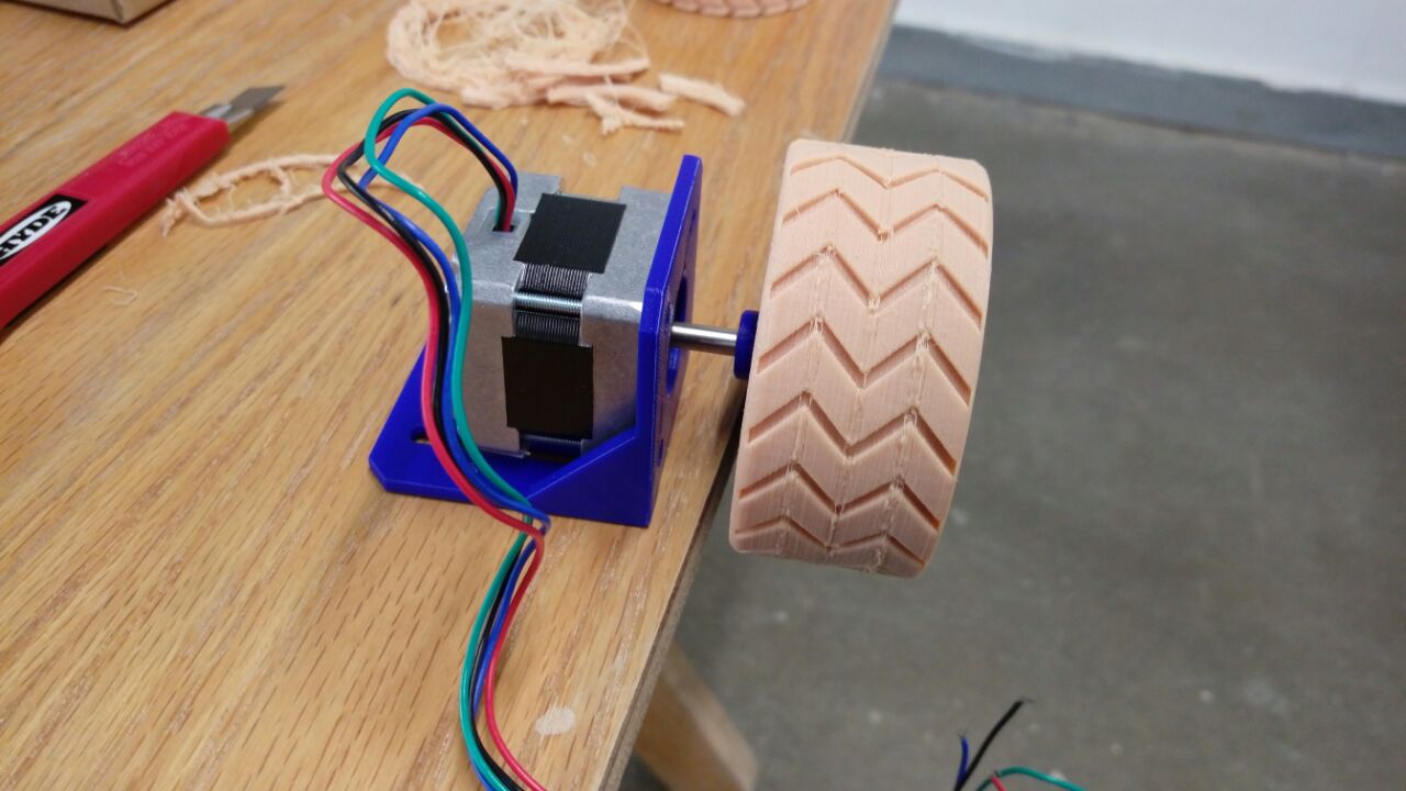
Last assemblyed result
As I mentioned before, I have an experience with FDM 3D printers, even that I learned many new things this week. Now I have a good understanding of what printer's strengths such as the ability to print complex shapes and limitations such as long printing time. Also, this is my first time working with materials other than PLA, which surely differs in properites and settings, additionally this is my first time trying SLA printing technology . The most useful lesson I learned while producing final project part is to be patient !! ! because whatever you think it's easy to produce a successful product it will NEVER WORKS FROM THE FIRST TIME !!.
FDM vs SLA printers:
The difference which I noticed between SLA and FDM printers are: FDM is simpler to understand how it is work easier to deal with, setup, monitor... etc. but it is lower quality than SLA. From other side SLA is higher quality and provide more complexity in printed designs, but it is much slower, needs more attention in settings and setup, work with hazardous material and more expensive than FDM Technology.
Ultimaker 2 vs Witbox printers: both are FDM printers very similar in most of the steps I used the same software (Cura) to generate G-code for them. The LCD screen interface little bit different also Witbox has larger print size, but no heated plate on the machine bed. Generally in our lab most of times they use Witbox for flexible materials and Ultimaker for PLA ( the reason is the flexible material needs to be near extruder to avoid slipping, nothing special with witbox extruder but the lab team added some extra parts to fix the filament roll above the witbox ^_^ ) .
Download my designs: