This week is about machining different materials using computer controlled machines, also known as CNC : Computer Numerical Control machines these machines transfer designs from CAD files into desired objects by executing a sequential commands called G-code. G-code generated using CAM any software.
The task of this week is to make some thing big using wood without any glue and screws just with joints!.
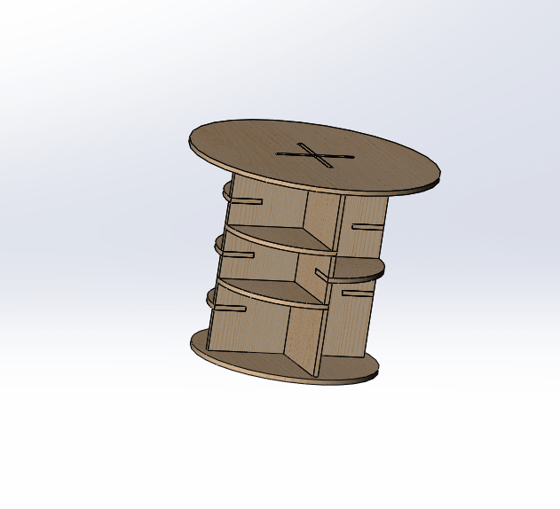
I decided to design a small table using
![]() . First try was a circular table with many racks to kill two birds with one stone. But the result wasn't beautiful as I expected its functinoal but something missing!.
. First try was a circular table with many racks to kill two birds with one stone. But the result wasn't beautiful as I expected its functinoal but something missing!.
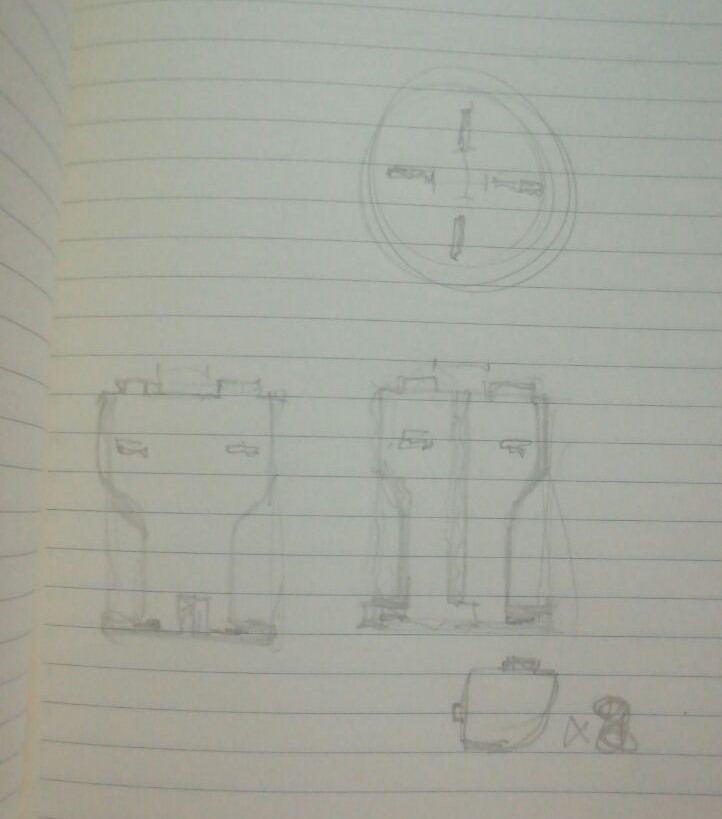
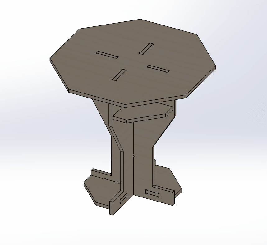
In my second design I had a help from an architectural engineer. The table had the same function and size, but surely it looks much better than before!. Of course mechanical engineer desgine beauty is incomparable !! The sketch of the idea:
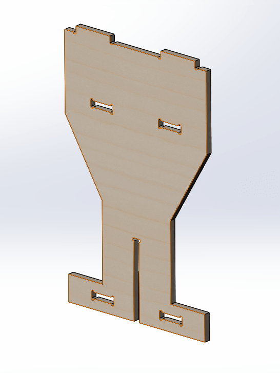
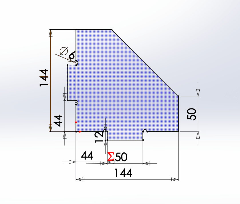
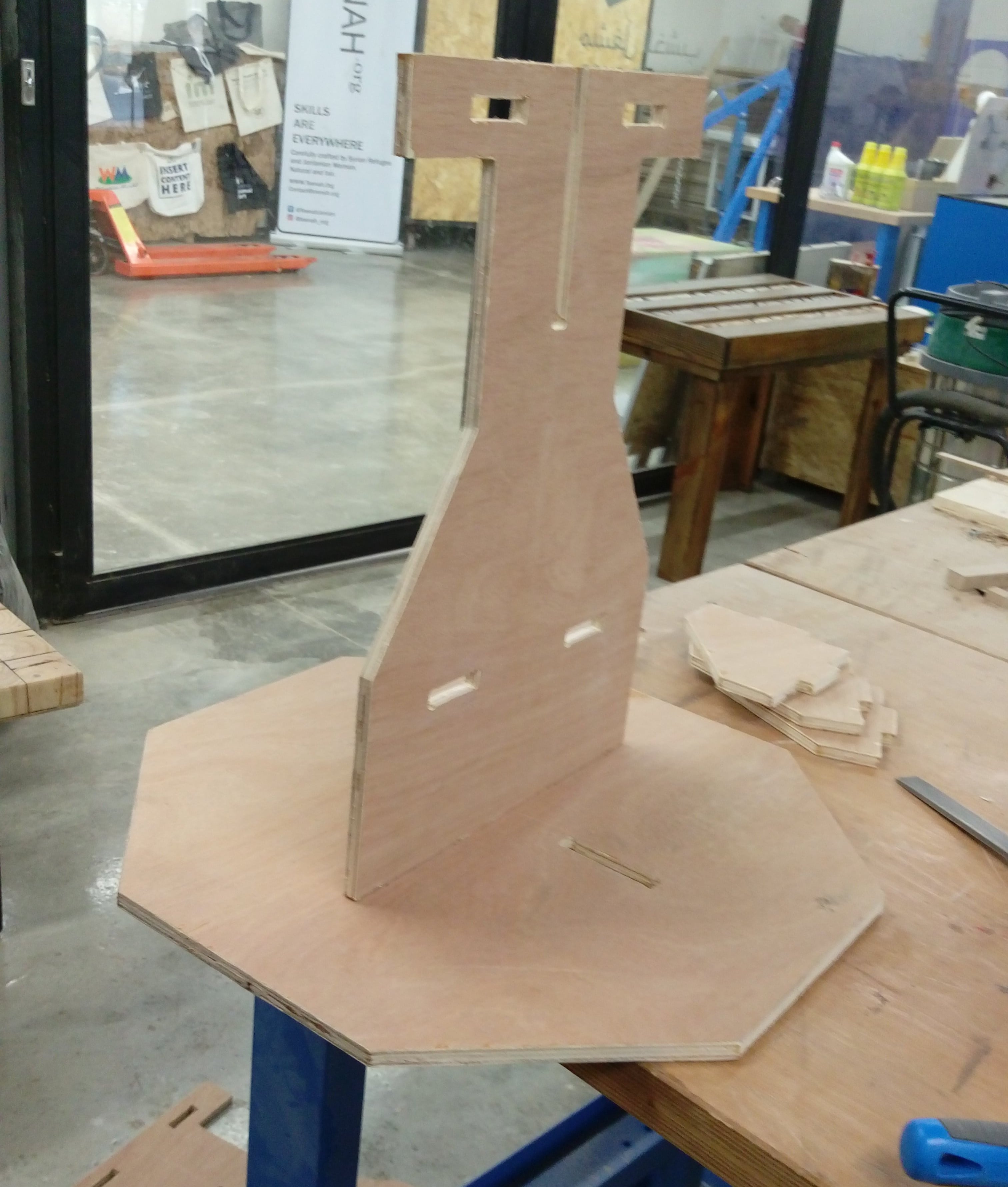
I start drawing a sketch for the stand of the table which is consisted of two crossing parts.
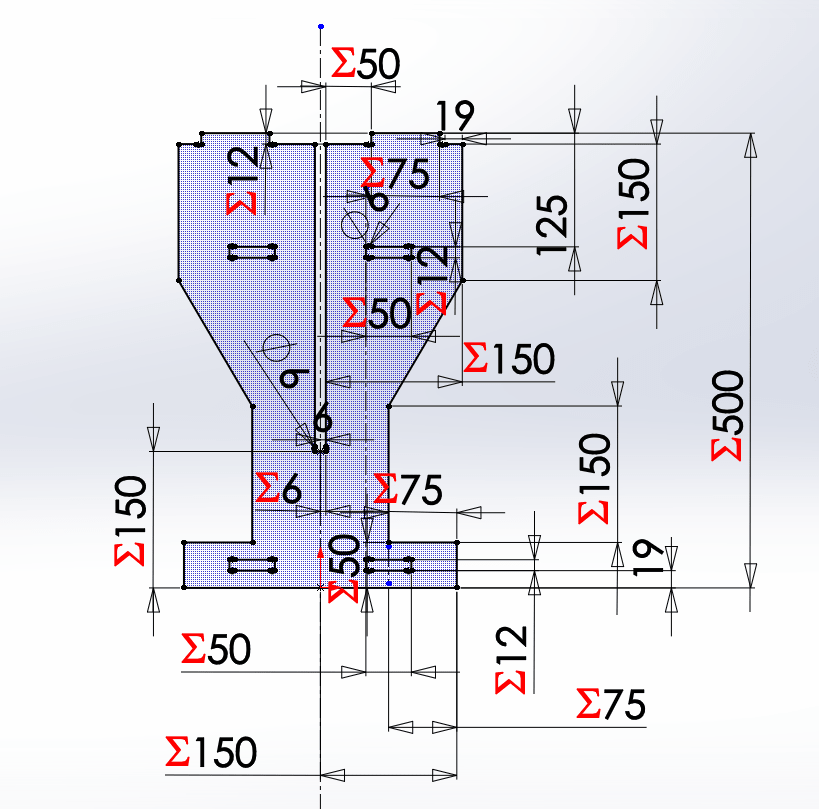
Then I extruded by the thickness of the wood board (12mm)
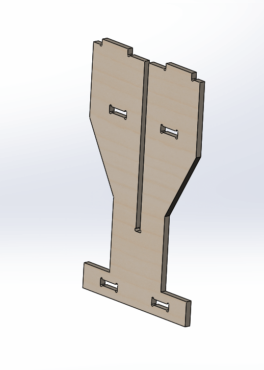
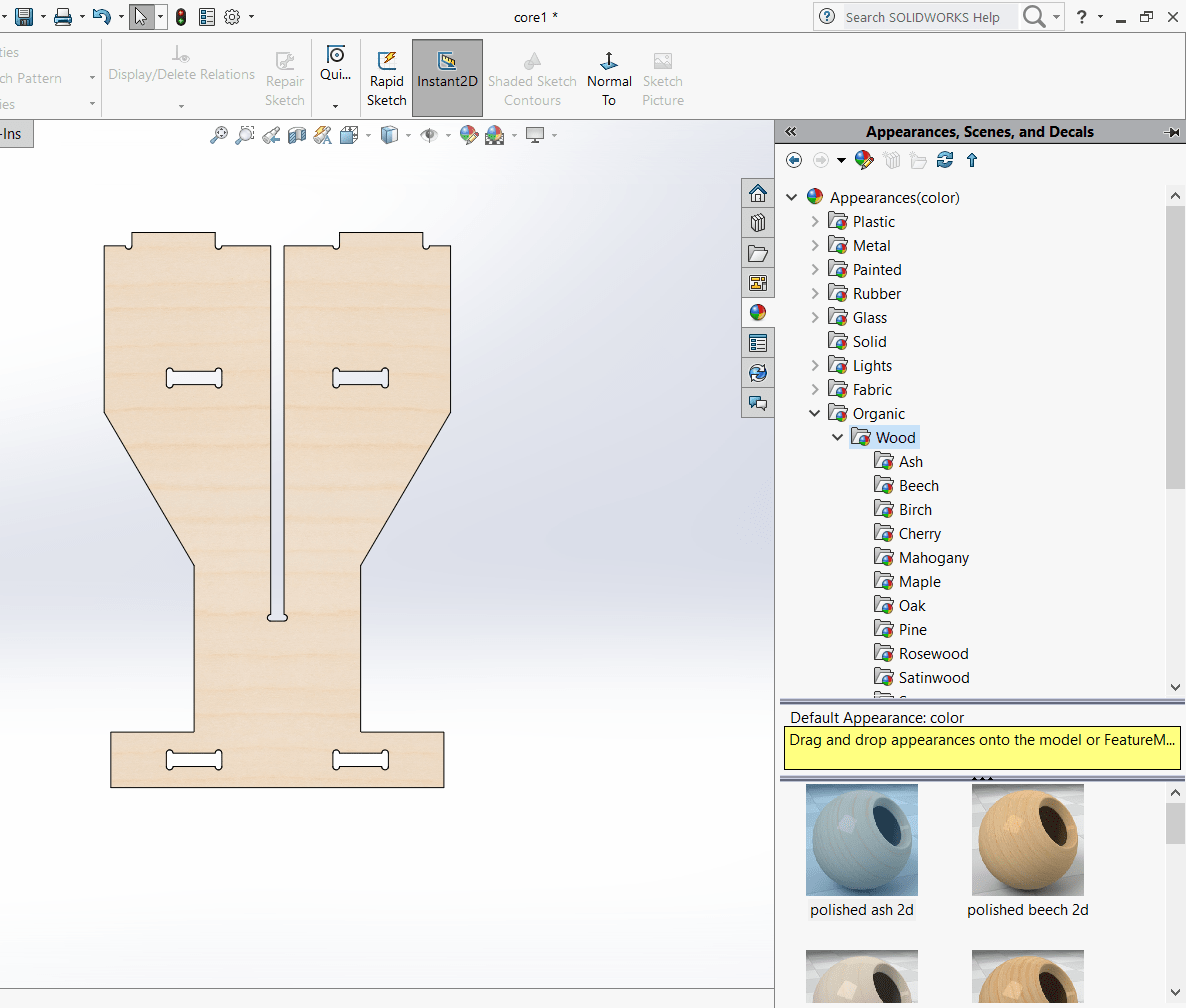
To make it look like wood I changed the apperance of the part as shown:
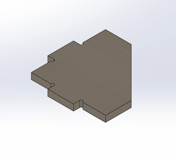
The same as previous part I designed the second one to look like:
To add more stability to the table, also it could used as racks I designed this piece:
The final part was the top of the table, it could be any shape I designed an octagonal top .
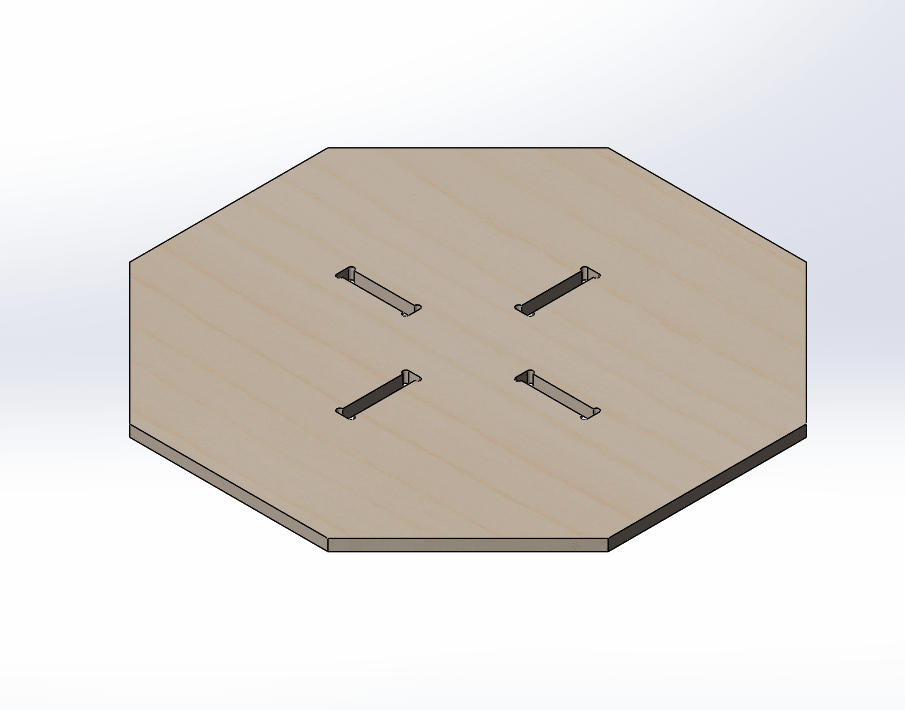
From my previous experience of Solidworks I added all previous parts to a new Solidworks assembly and make necessary mates to make sure that all parts will connect without problems and to see how final looks like.
Then I saved a top plan for each previous part ( sketchs before extruded ) as .DXF files because many 2D CAM softwars accept this format.
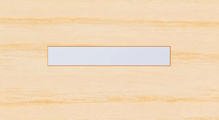
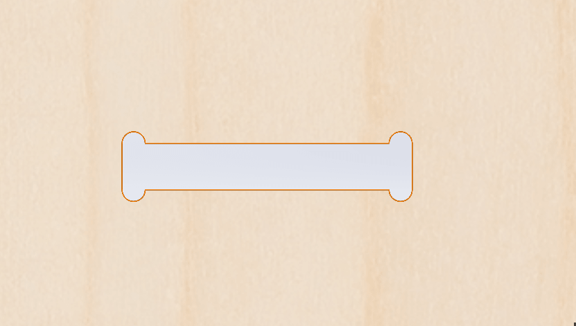
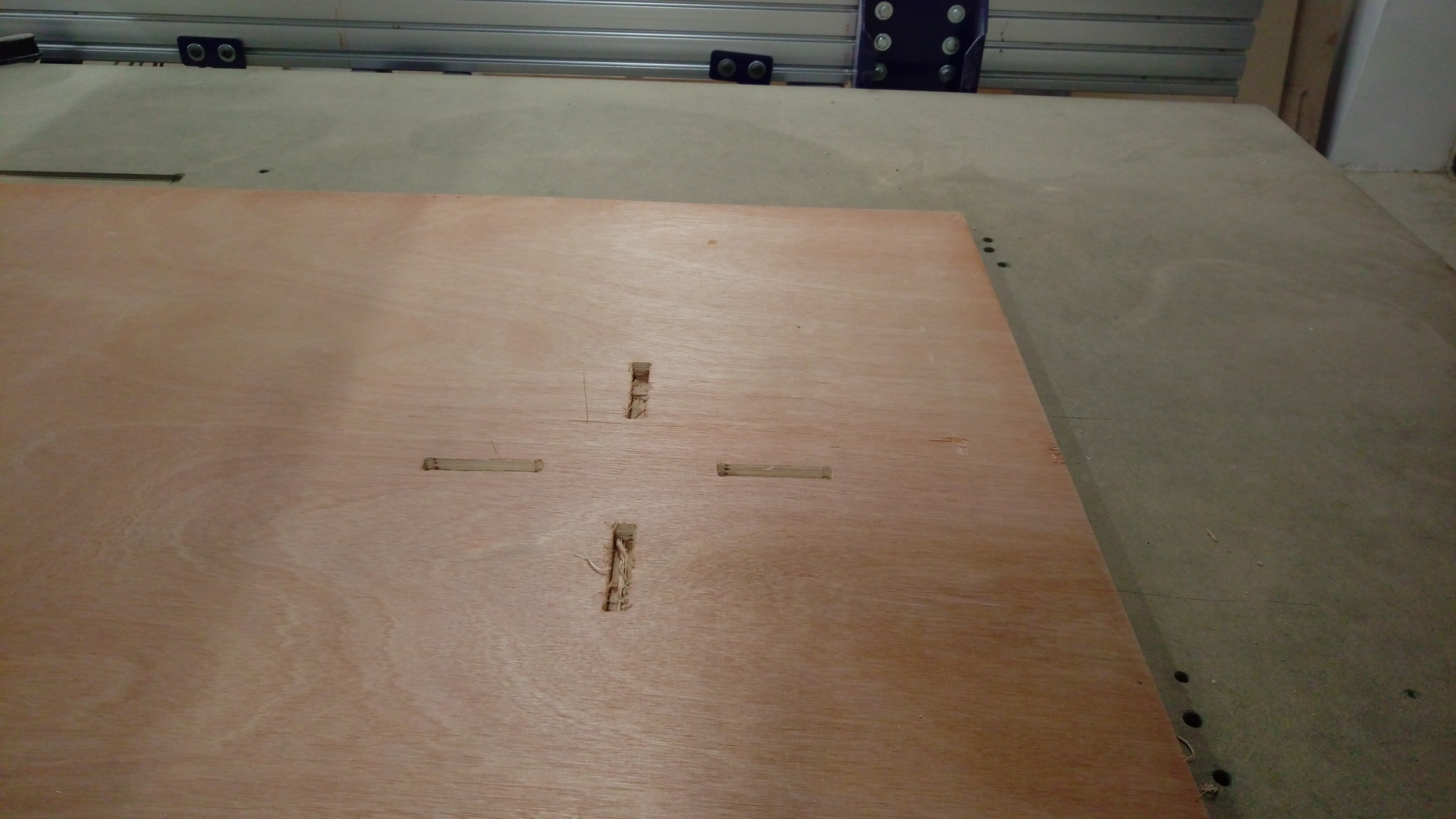
I really had a very significant mistake with the design of the joints. My first design was just a rectangular then I know the tool will never make it 90 degree and there will be fillets and it will not fit. So I repeated the design and fixed the joint, then test them before cut whole desgin.
This two picture for wrong and correct desgines
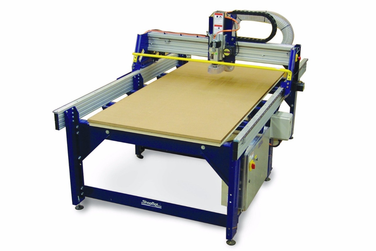
In our Fab Lab we have a ShopBot CNC
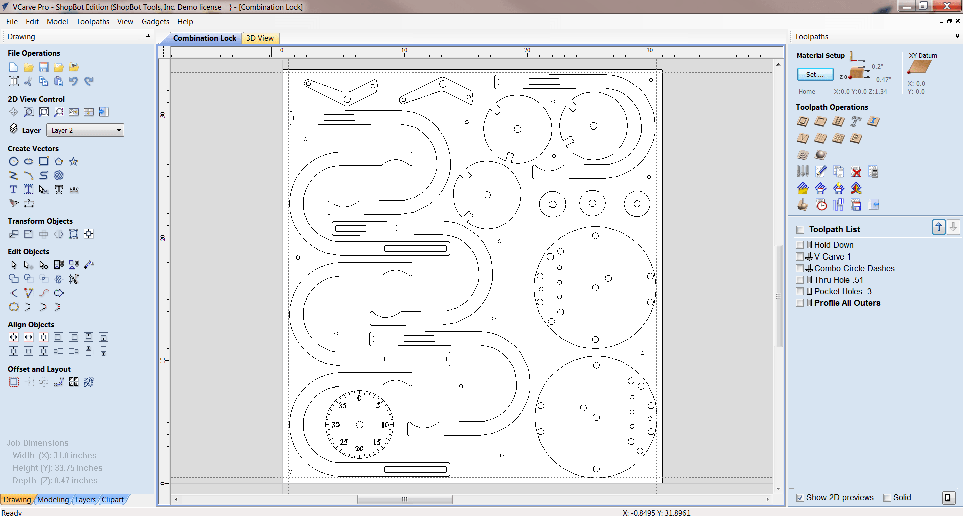
The same company had a simple design and CAM software compatable with ShopBot calls VCarve Pro
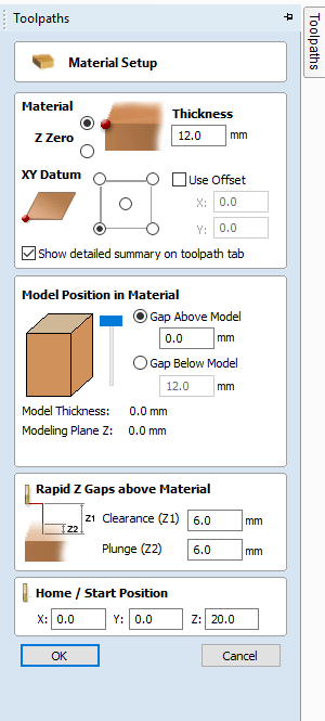
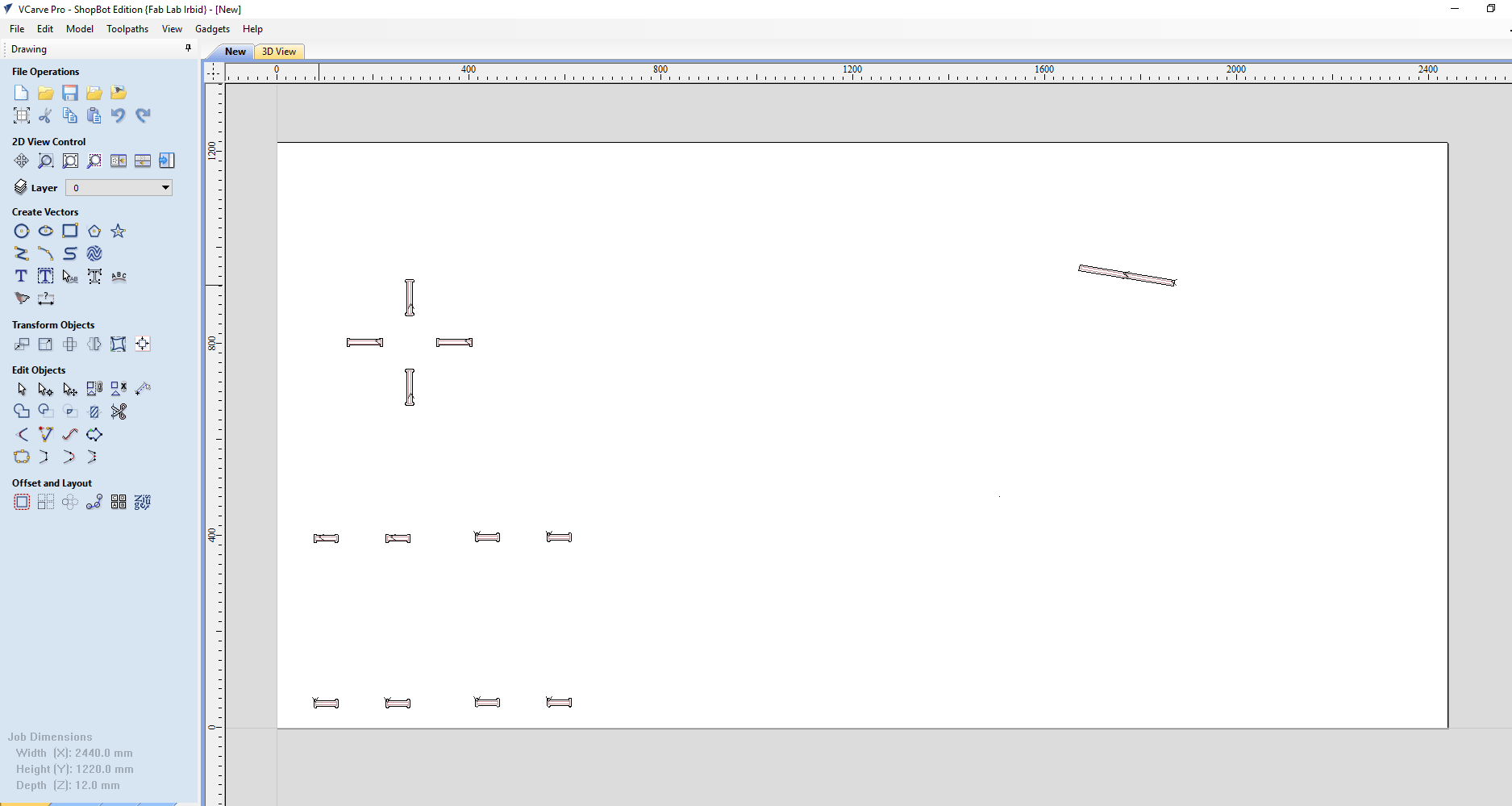
Start by identifying boards diementions X= 2440mm Y=1220mm Thickness = 12mm, and select where is machine zero point on the board. as shown:
Then I imported all DXF files (one for each part, except corner, I need four of them (, when I click on any object, it will select individual line so I used Join
![]() from Edit Objects bar, so now I could select whole shape.
from Edit Objects bar, so now I could select whole shape.
Then I arranged all parts on the board, leaving aproccematly 30mm apart from frame, and some space between parts. Because my table was small I add some parts of Kusais's chair Kusais's chair. Finaly, this was how my board looks like:
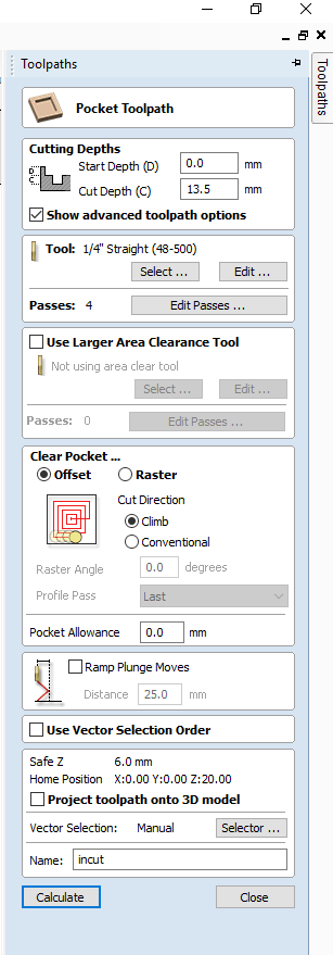
Now from Toolpath Operations I chose bocket
![]() to cut inner joints, select them and edited settings as shown:
to cut inner joints, select them and edited settings as shown:
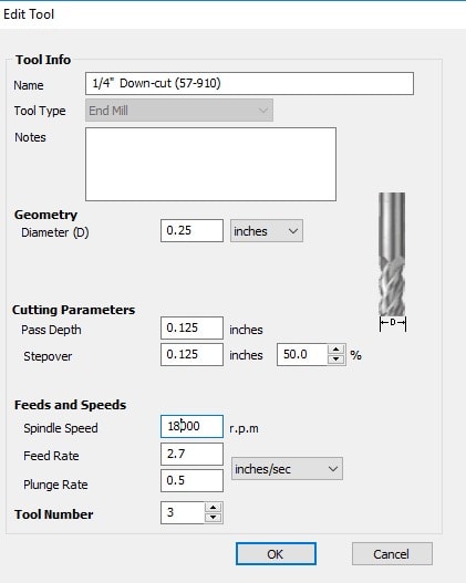
Settings for spindel
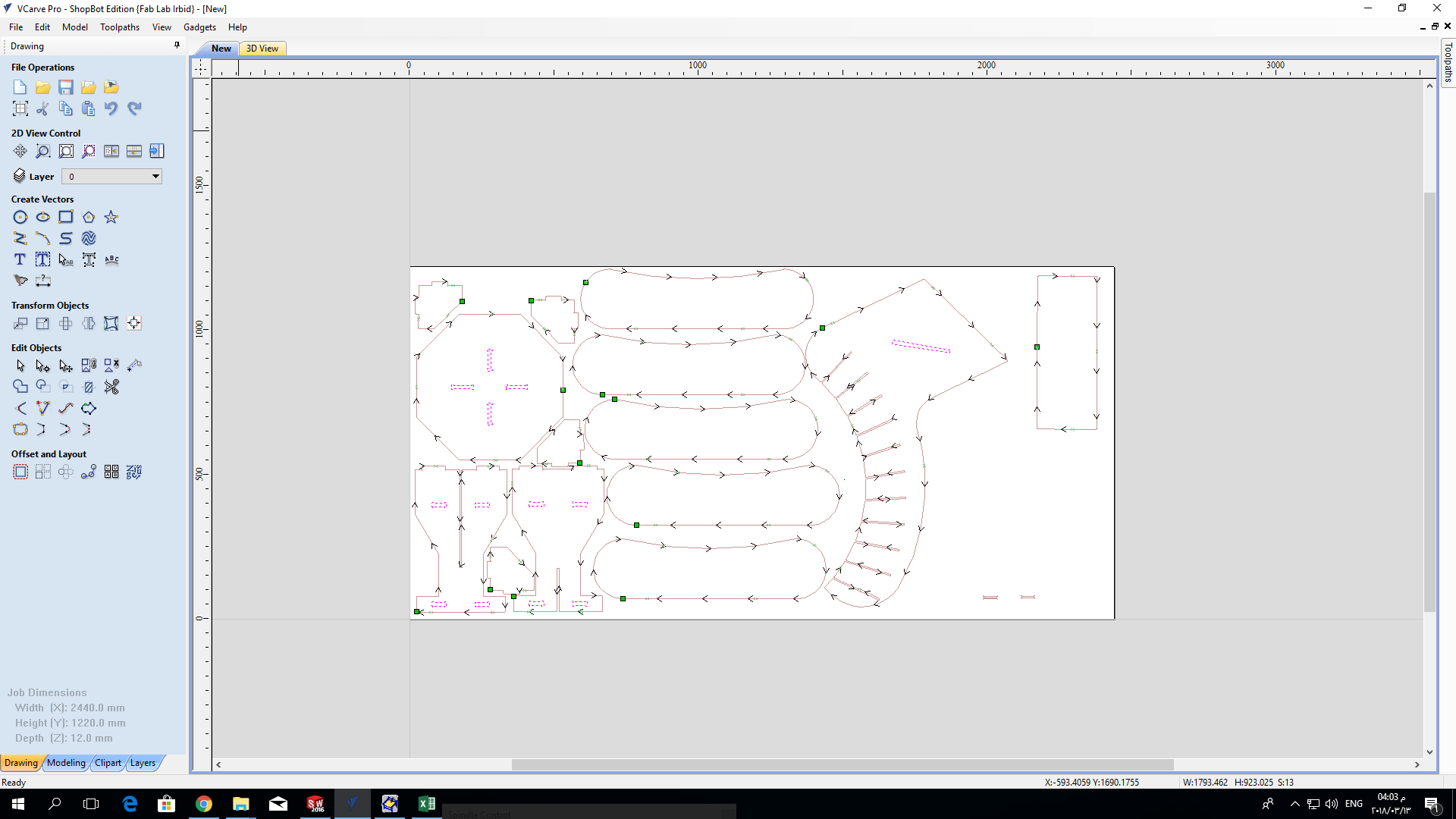
Then I pressed calculate to generate the path and the G-code. Then saved this toolpath. The output toolpath shown:
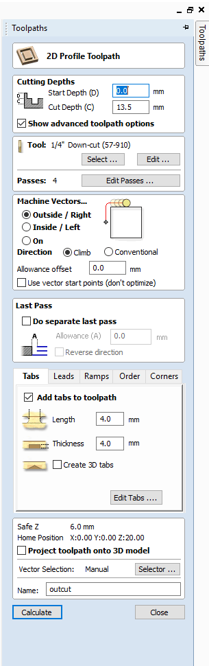
For outter cutting I repeated the same procedure, using countor ![]() opration with these settings:
opration with these settings:
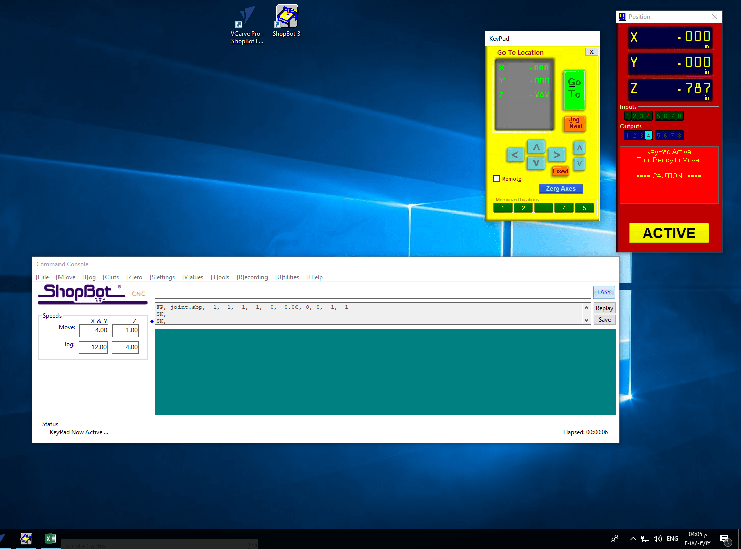
Now open ShopBot interface software, connect it to machine after turn machens two buttons ON ( one for all machine control system the other for spindle motor separately ) make show X and Y axes zeros are selected correctly. To select Z axis zero use the metal plate put it under the tool and connect the clip to it, click on the icon the machine will automatically slowly down the tool untill touch the plate, then it will save the zero point and raise the tool up.
Before starting the job the wood board should be fixed on the machine table, there are two options, one is screws using automatic screw driver the other is using staplers fixed by compressed air stapler gun the we generally using second method in our lab. While fixing staplers be careful to their locations and your design toolpath location to avoid crash between staplers and cutting tool.
After fixing the board move X and Y axes using KeyPad arrows 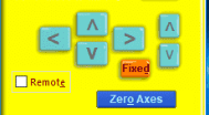 in the interface software to the zero position corner which should be identical with zero selected on software, disaster may happen you choose wrong corner. Zeroing Z axis is little bit harder, turn the spindle on and very slowly move Z axis down until you notice a change in the sound of the tool which mean that the tool touched the board this will be the zero of the machine. To be more precise you could put a piece of paper between the board and the tool.
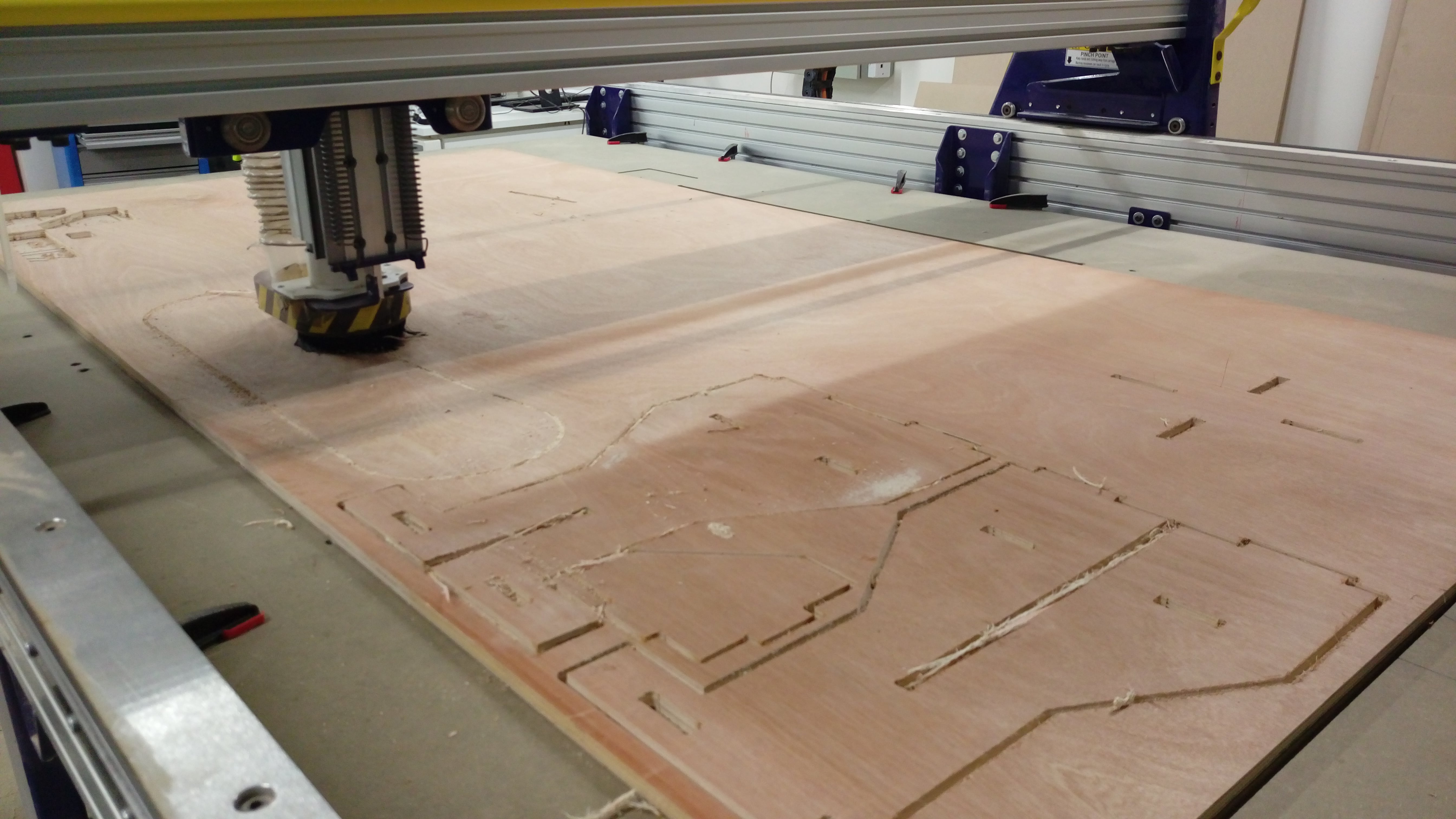
First choose inner cut toolpath and start the jop. While machine working on inner cut job
After inner cut jop complete start outer cut. While machine working on outer cut job
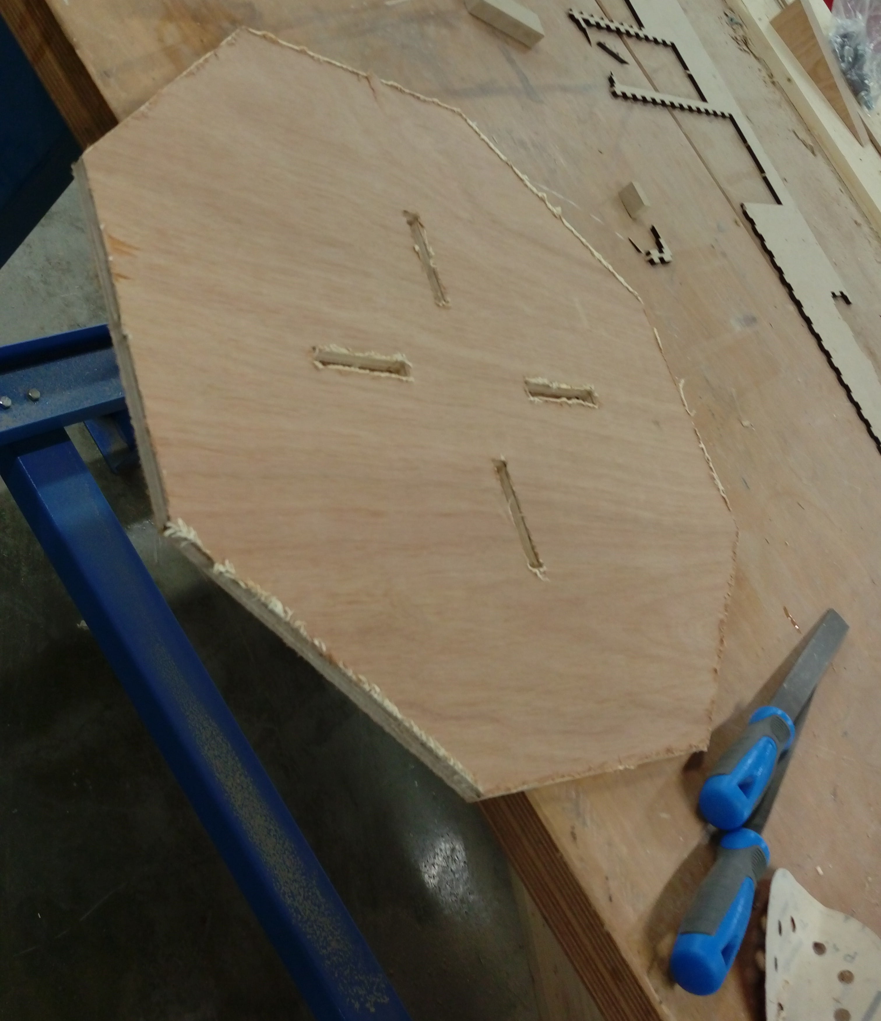
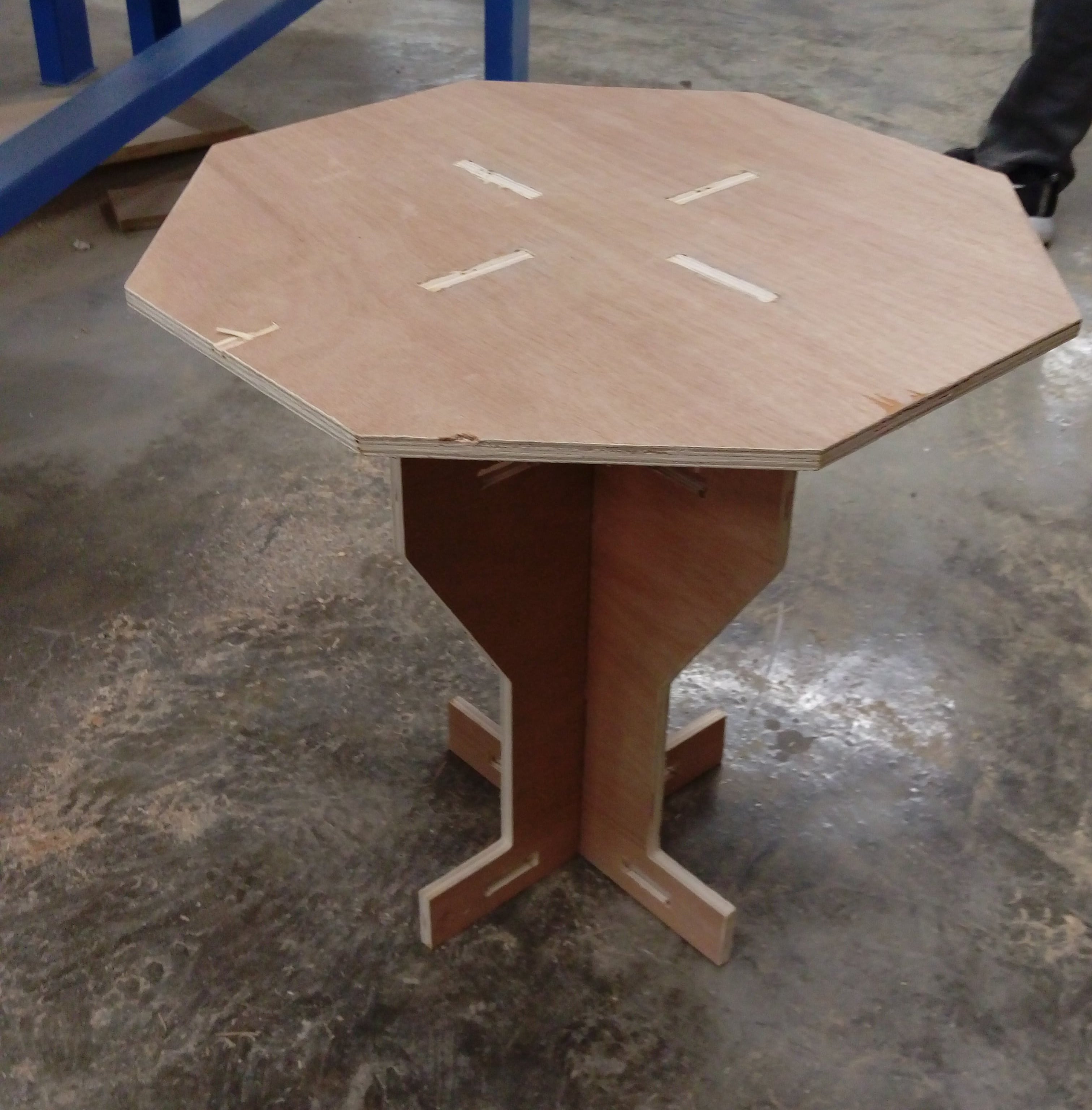
All parts after machine completed:
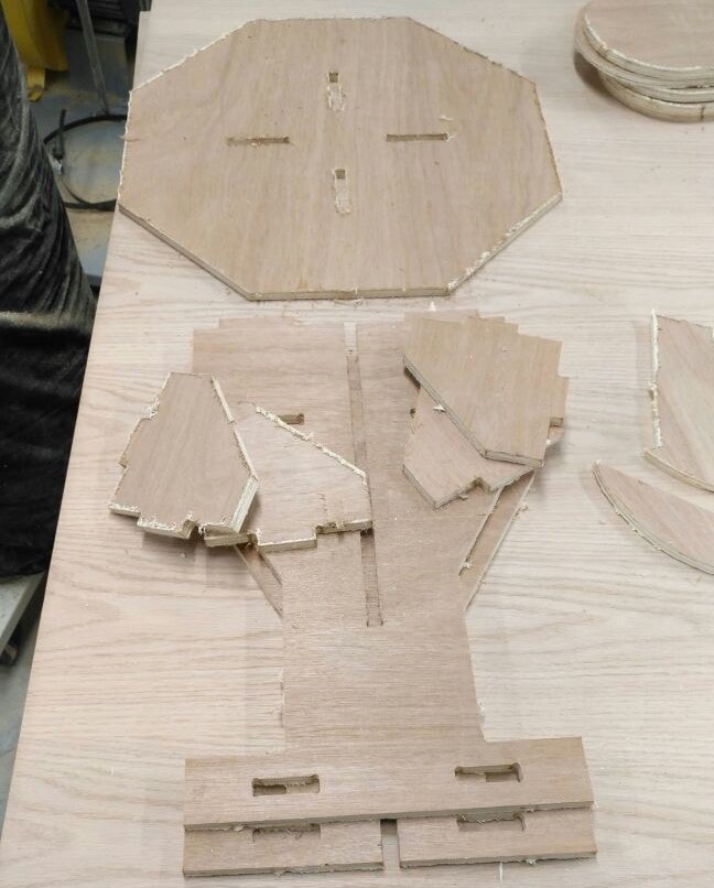
Unfortunately, The finishing of parts looks very bad
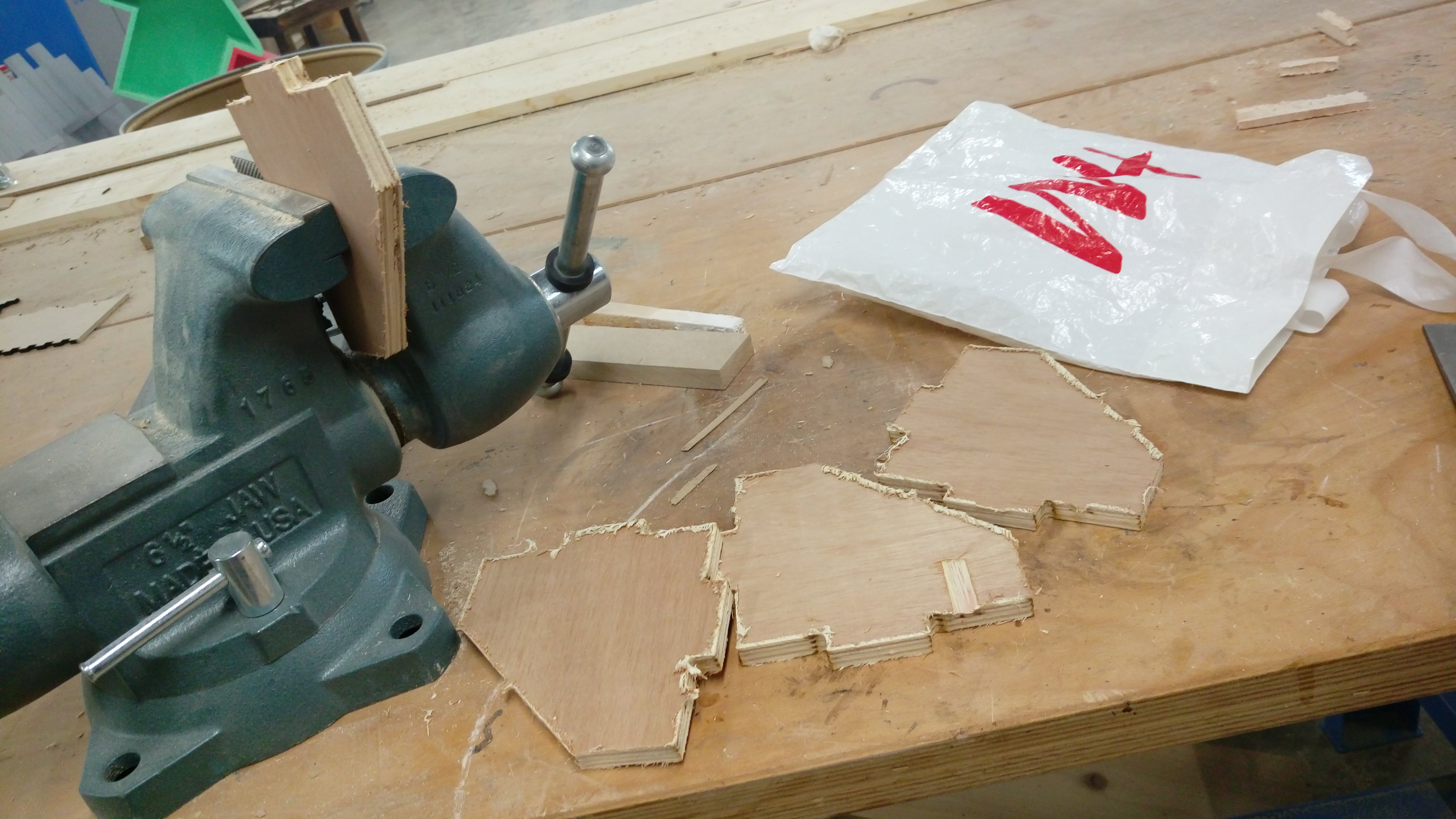
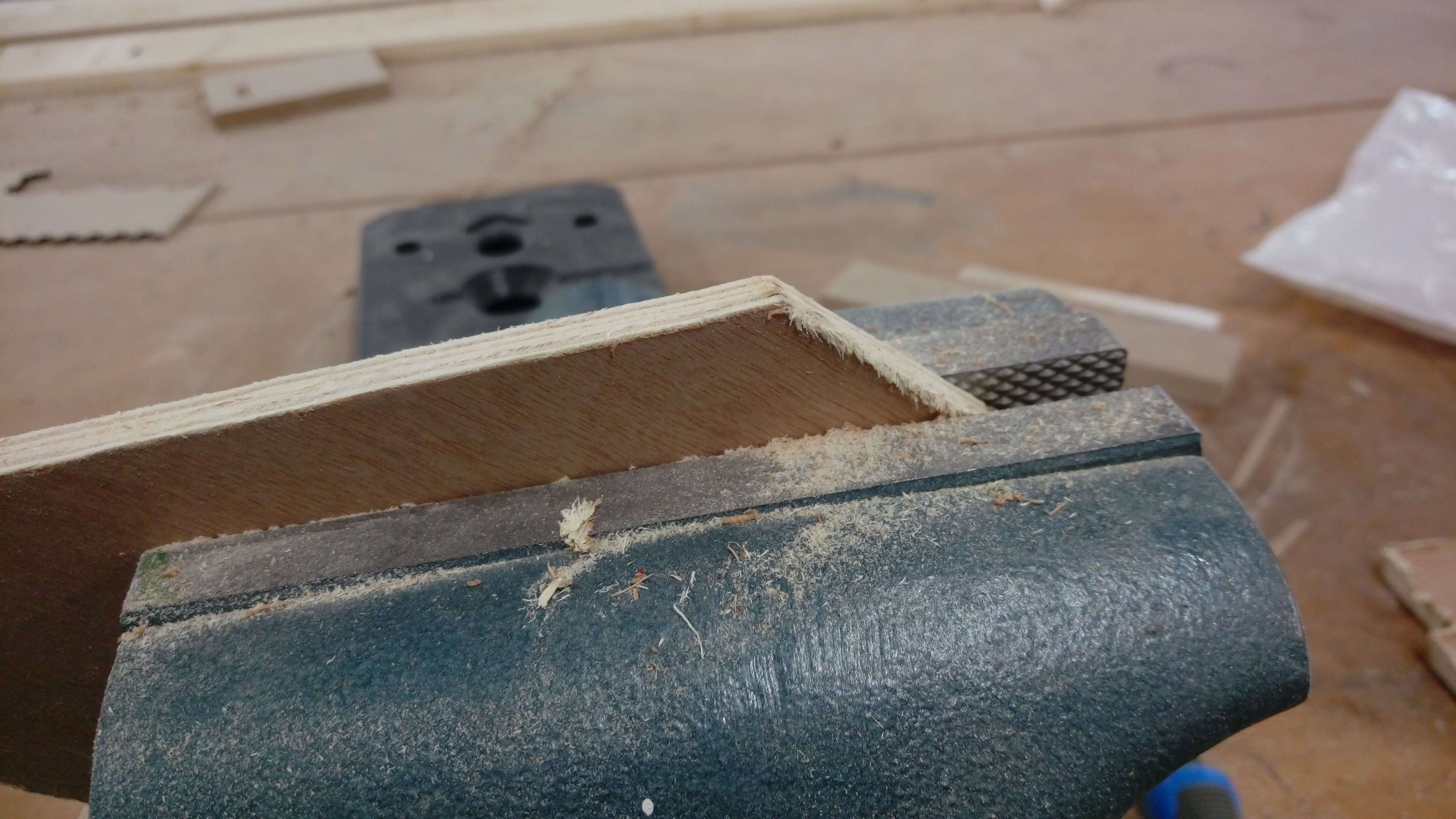
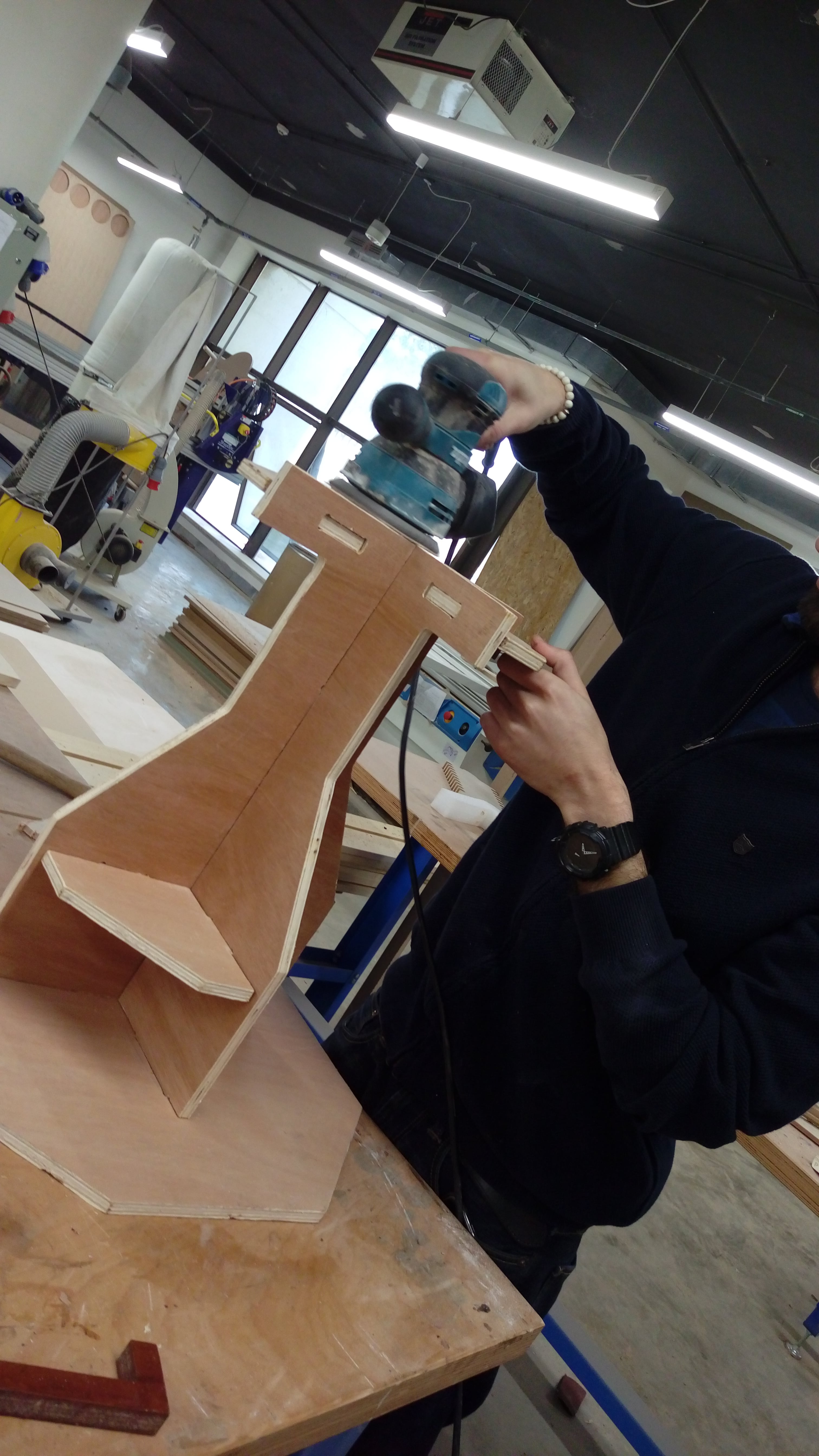
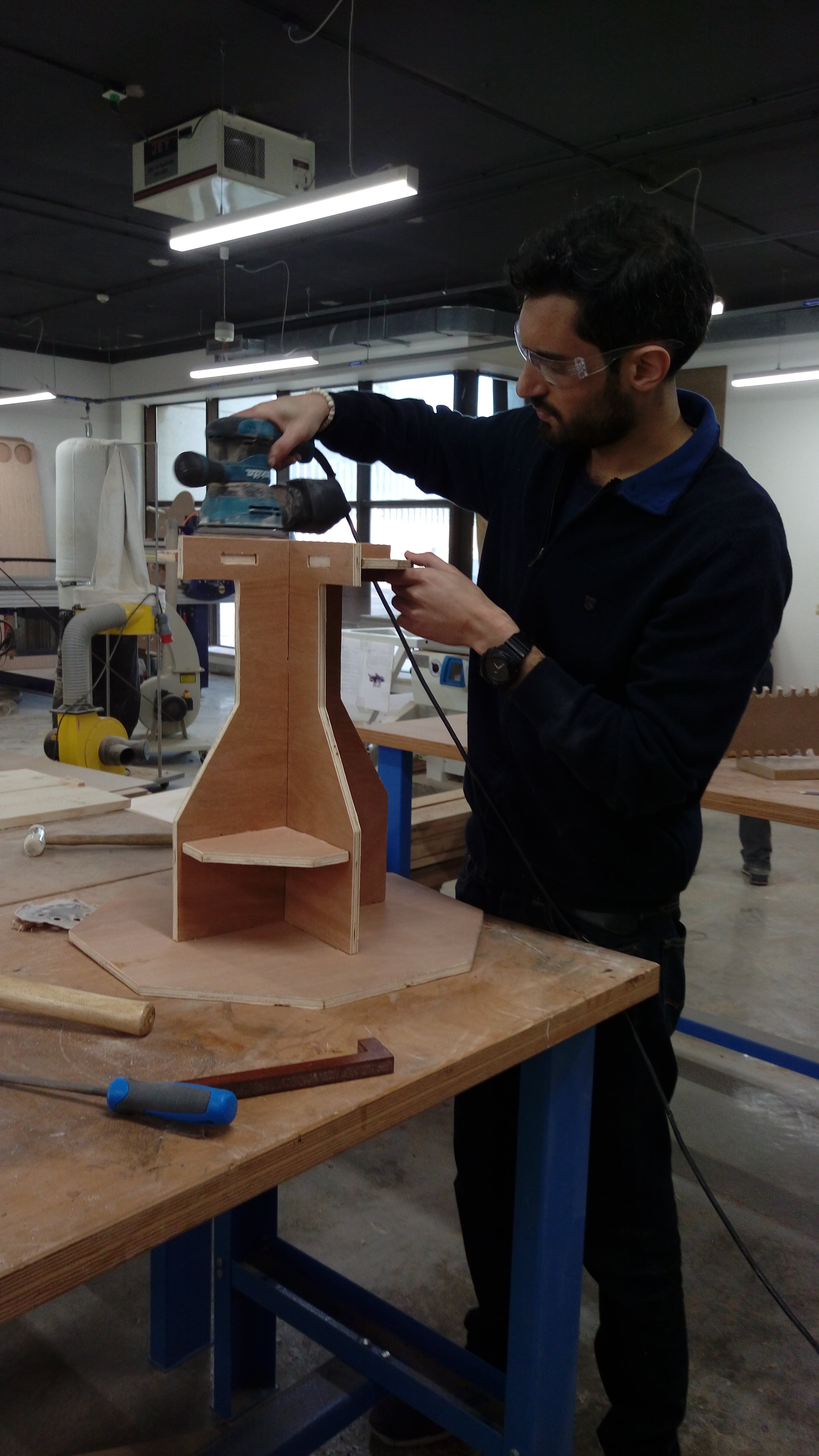
I spent time to sand edges using manual sanding tools
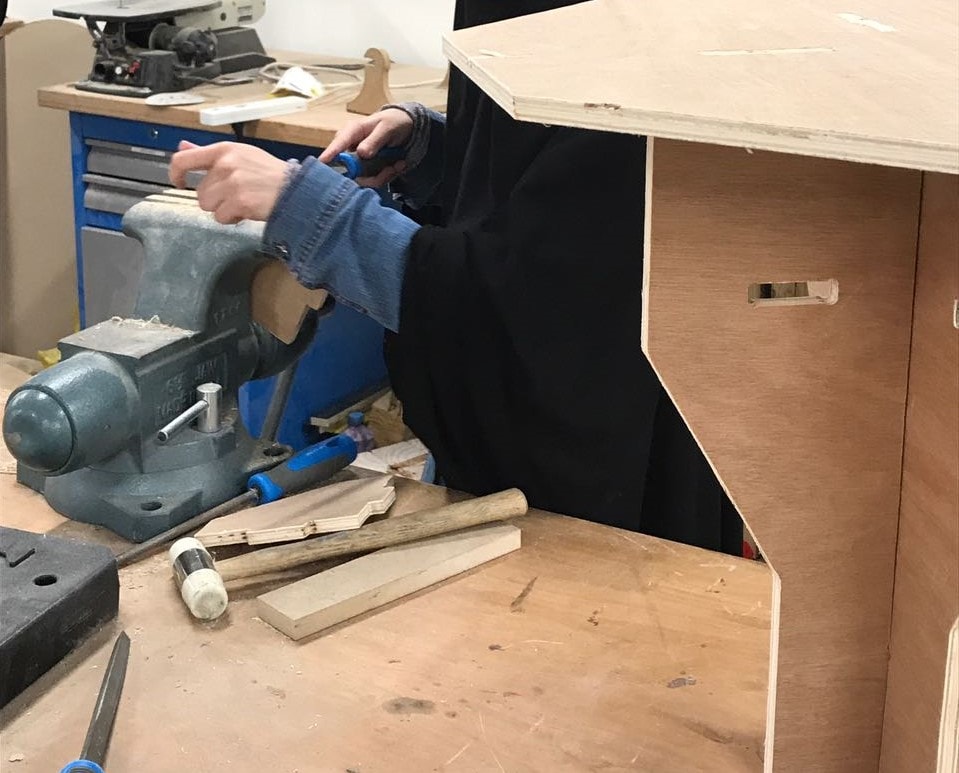
After sanding:
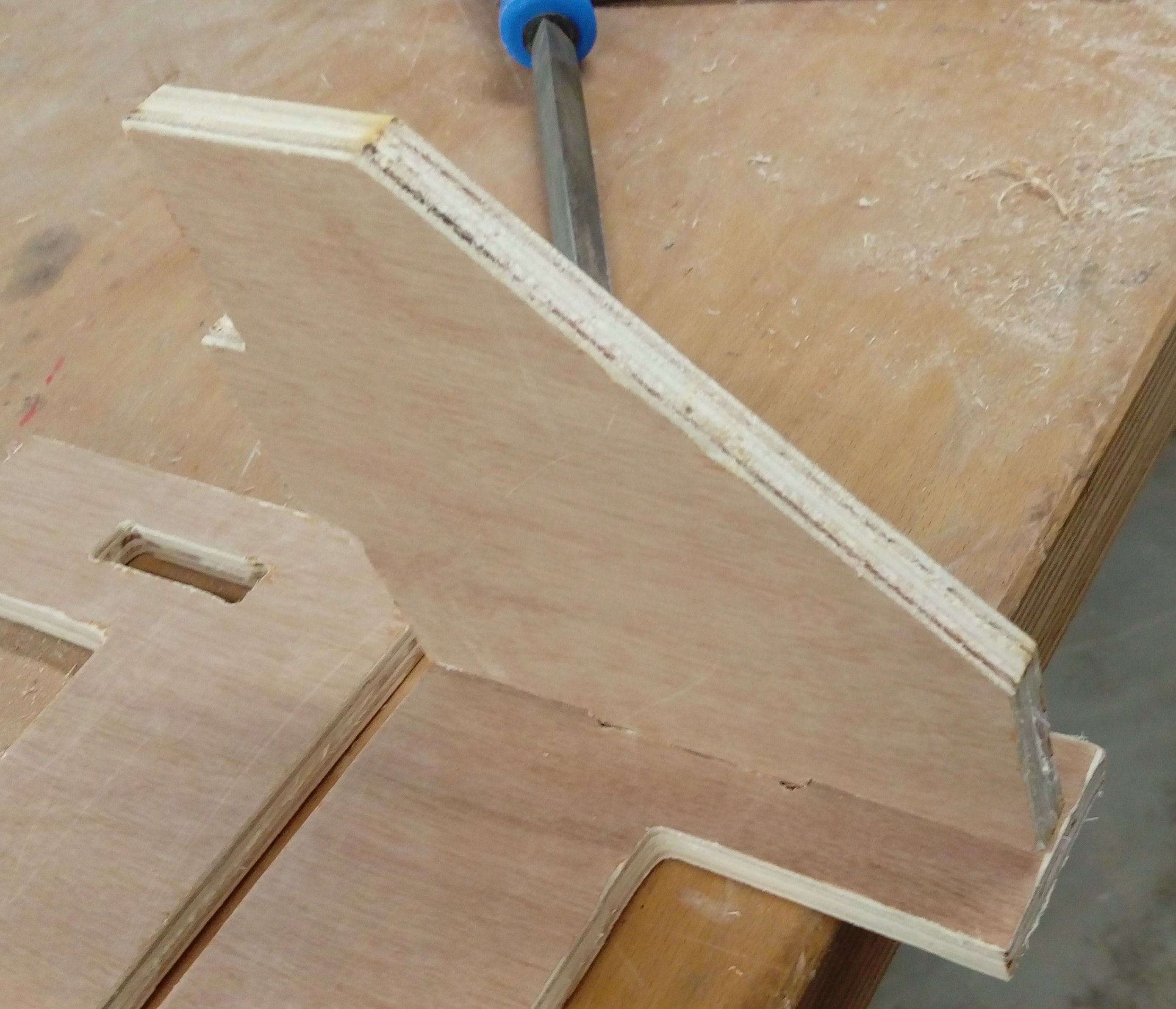
Some joint also needed a manual fixed to fit with each other :( Example of these joints:
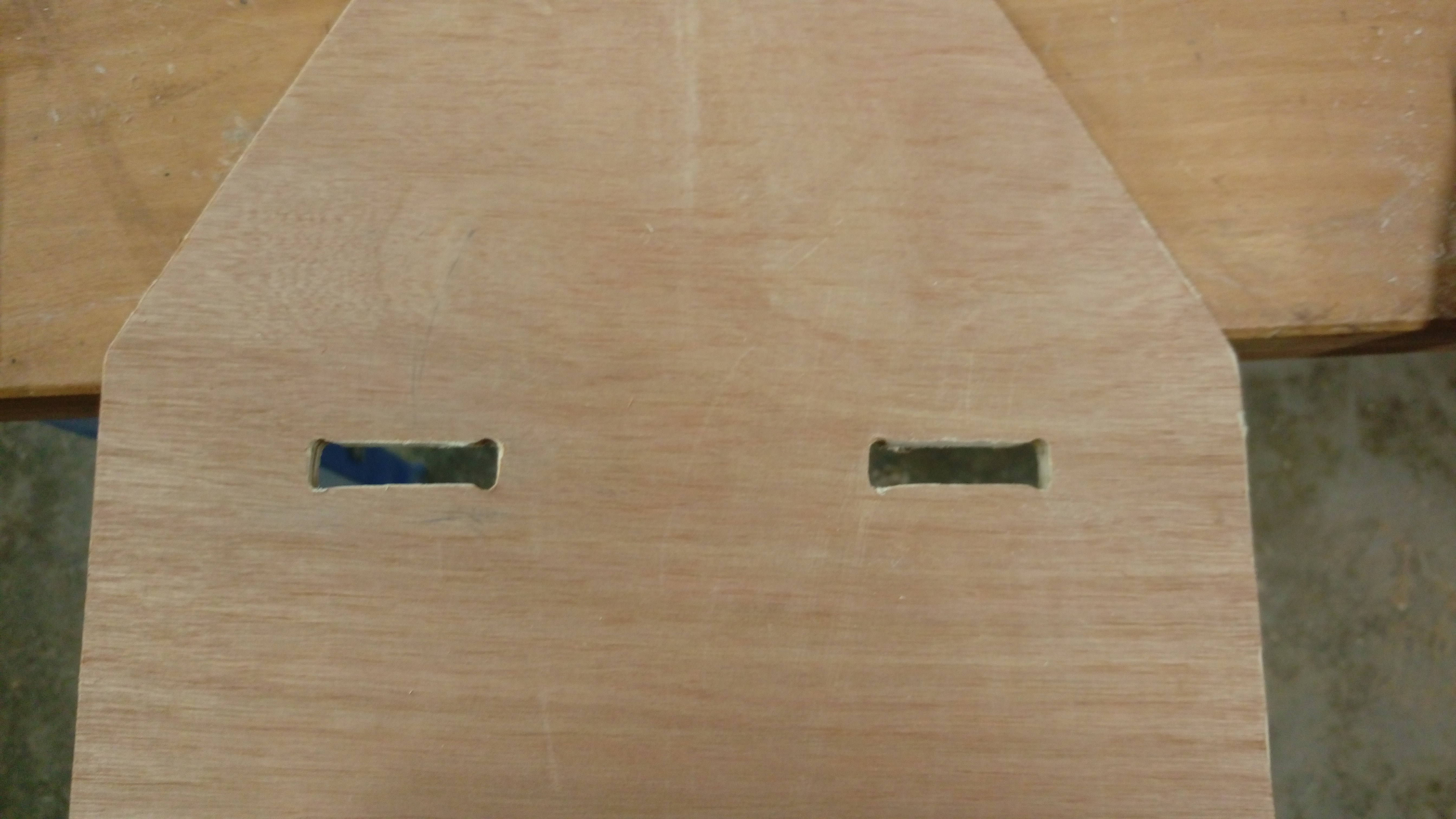
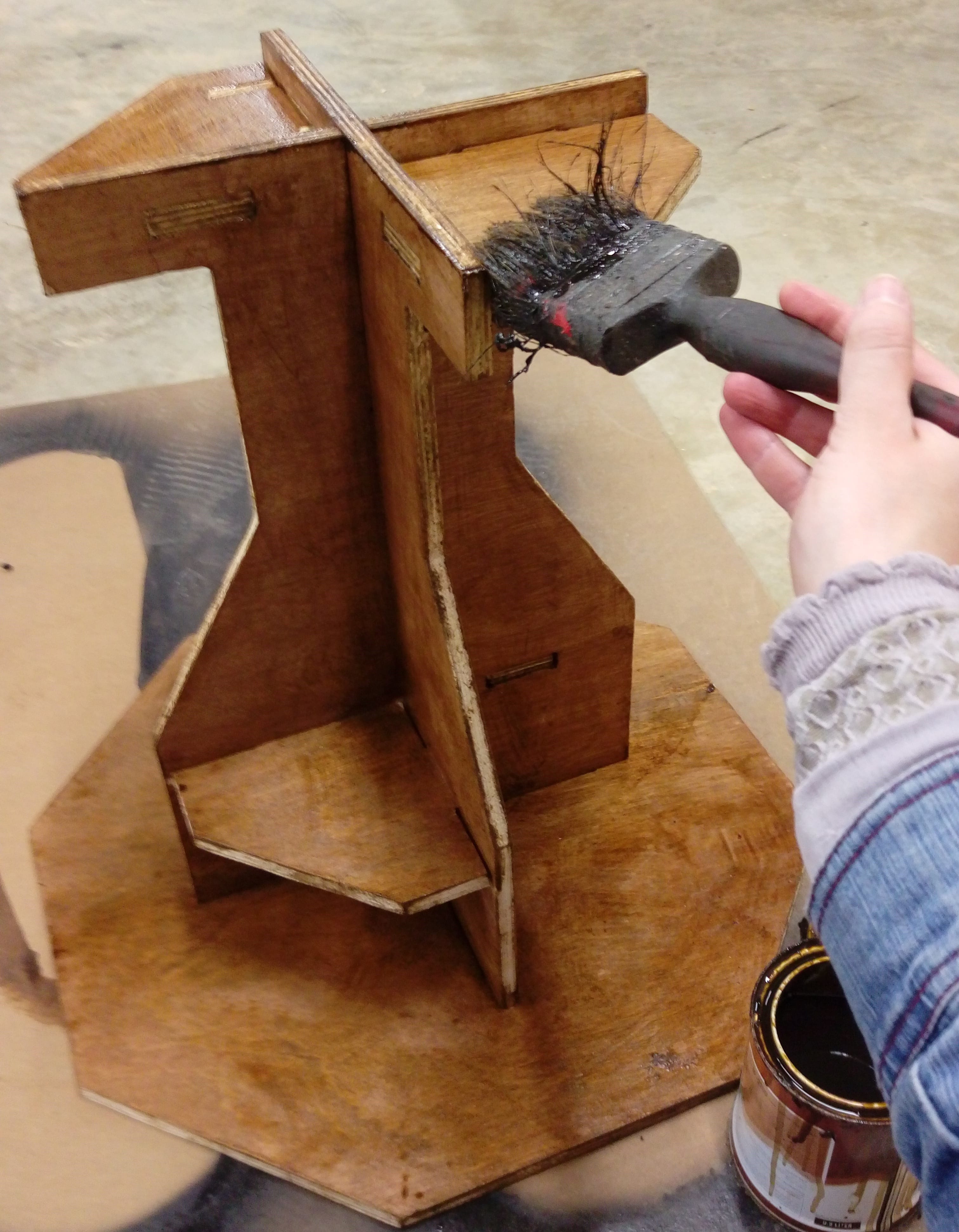
Table assembly, (I needed to use hummer for some pieces)
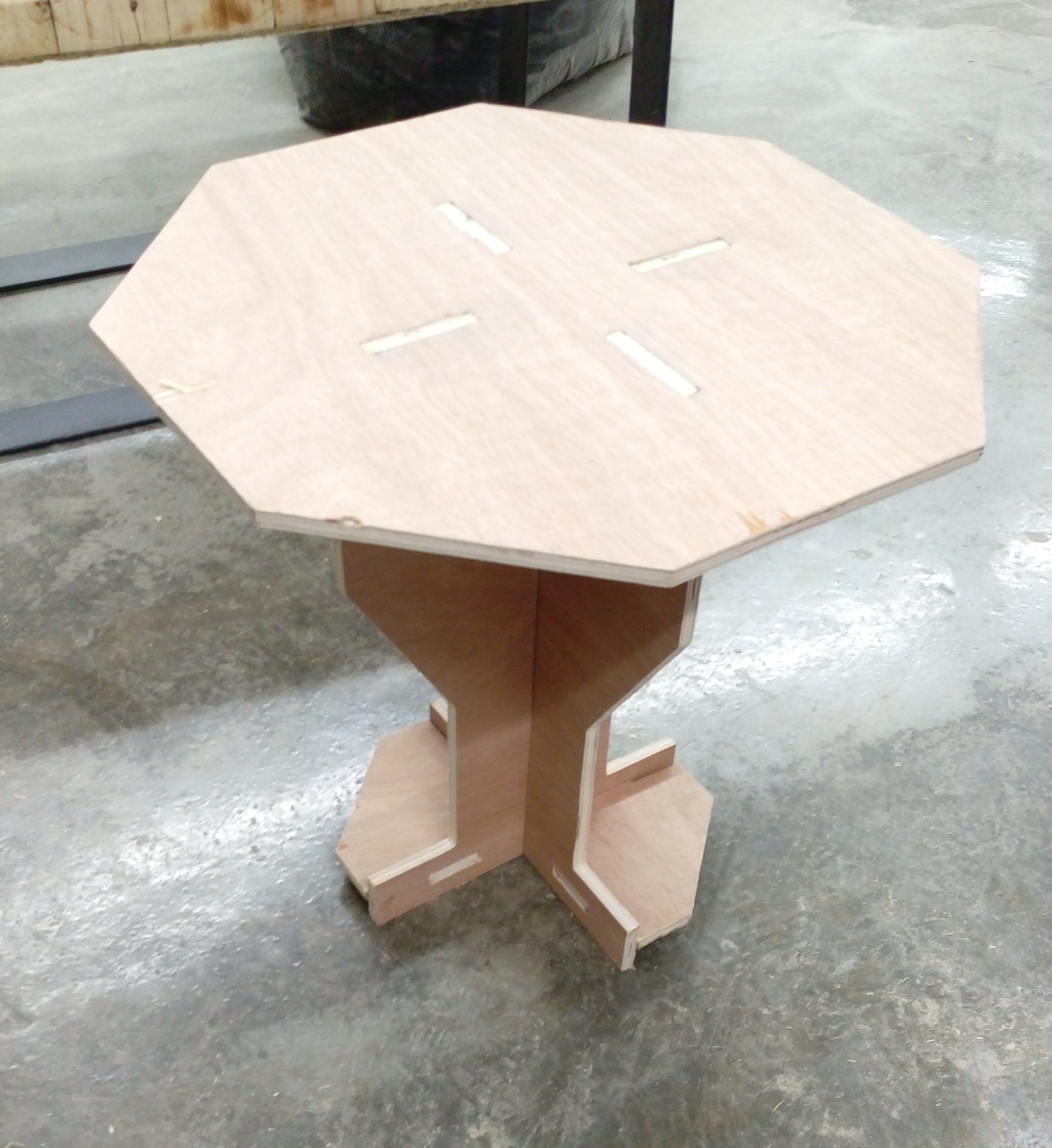
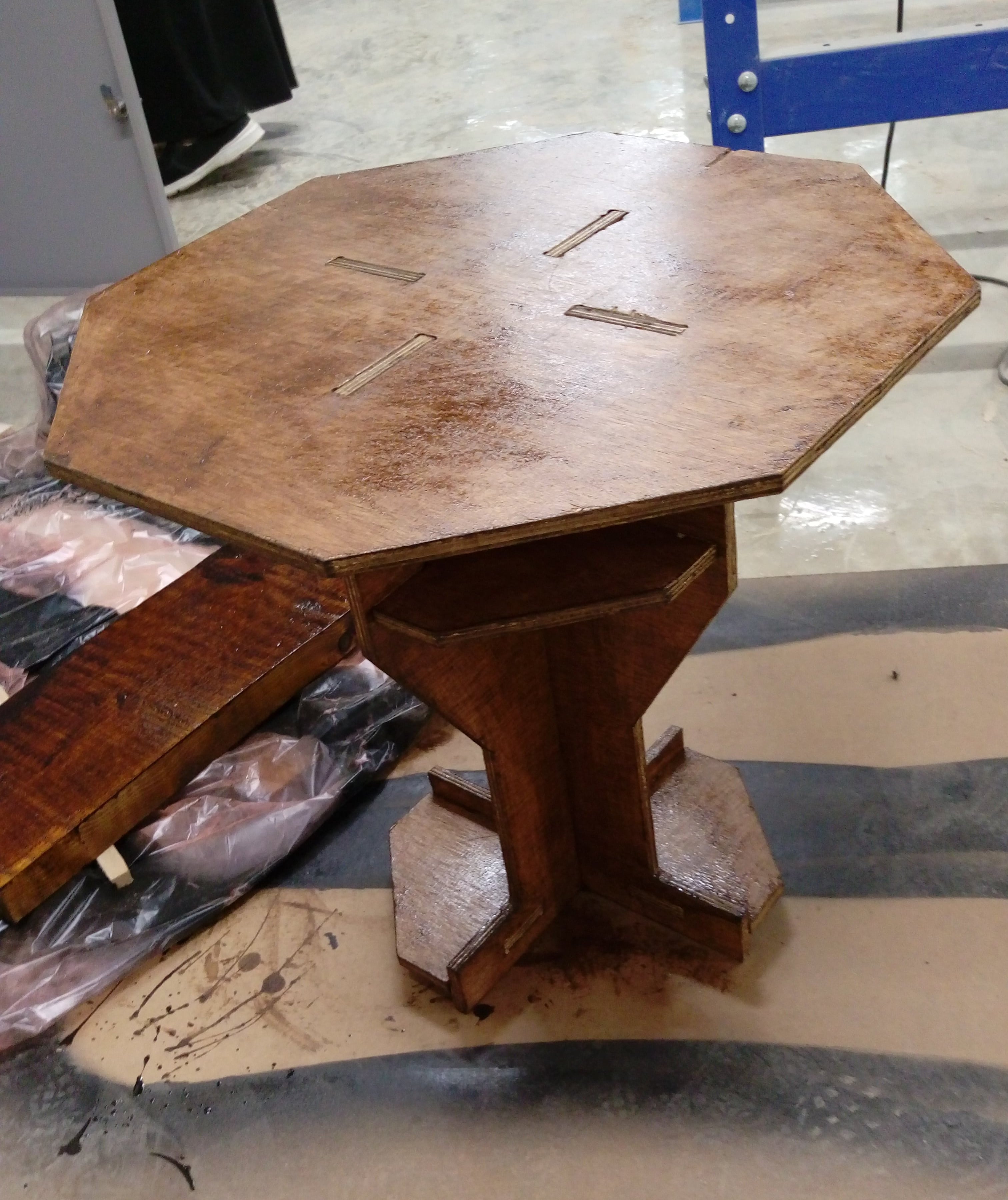
when I finished and put my table on the floar I notced that it isn't stable there is some unbalance :( . Some help from my mate Kusay Malahmeh to fix it ^_^
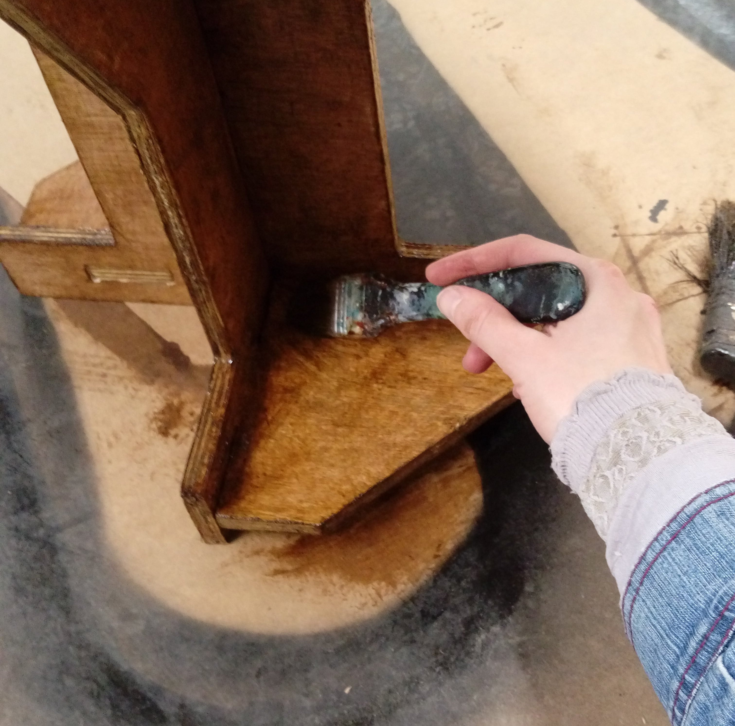
Time for panting
Finaly my cute table :)
You can download DXF files and tool pathes: