During This week we have learned how to cut different materials using laser cutter and vinyl cutter machines. It was a very excited but also a very tough week as a first practical experience, we learned a lot, faced problems with almost each step tried hard to solve some of them other we still working on them.
The tasks of this week:
The first assignment this week was a group assignment to find the best settings of the laser cutter (Power, Speed, Frequency and kerf) on several materials with different thicknesses. I select a wood to work on it.
Fab lab has a trotec laser cutter, the interface program is Jobcontrol ![]()
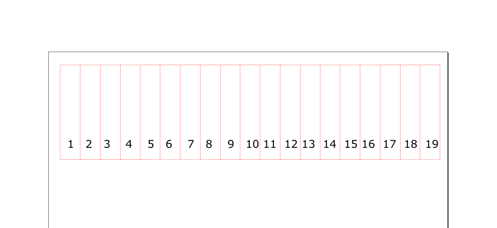
Firstly, design a test to calculate the kerf which is the amount of material removed by laser while cutting one line. One of the methods used to find a kerf is to draw a line with specific length and make several cuts along it, then collect the pieces and measure its whole length find the differences between design and actual lengths then divide it over a number of cuts along the line.
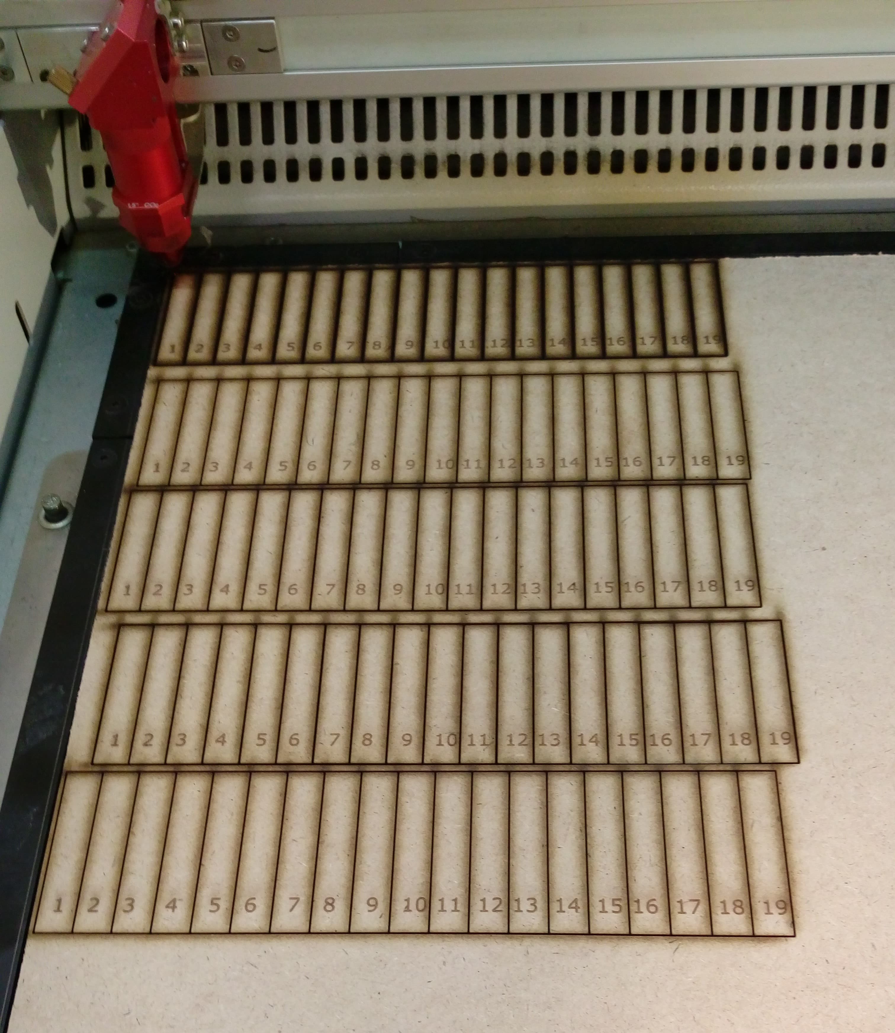
Using Inkscape I draw a horizontal line with 200mm lengths and divide it to a 19 slots ( using 20 lines ) as shown in figure below Make sure that the color of the stroke is Redwith0.1mmthickness and numbers have a black color.
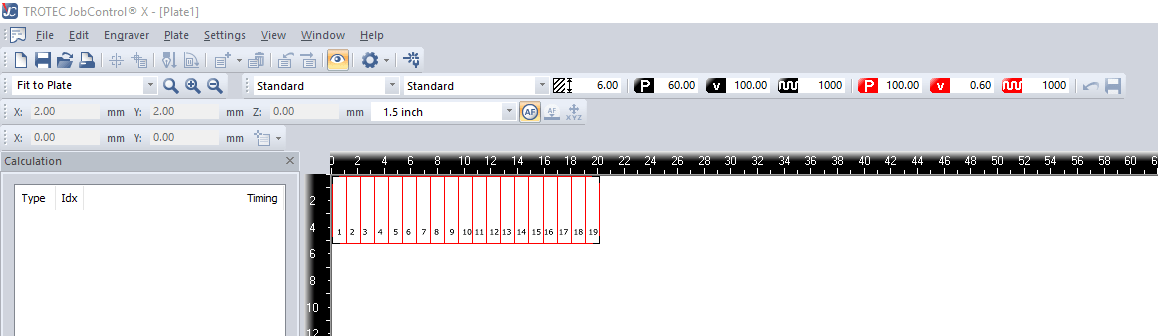
Now just press Print in Inkscape, then the file will automatically added to Jobcontrol here I start to PLAY with settings to find the best for each material.
I started with Plywood with 5mm thickness I made the test and the best cutting settings was:
Power = 100 speed =0.6 Frequency = 2000.
The result was:
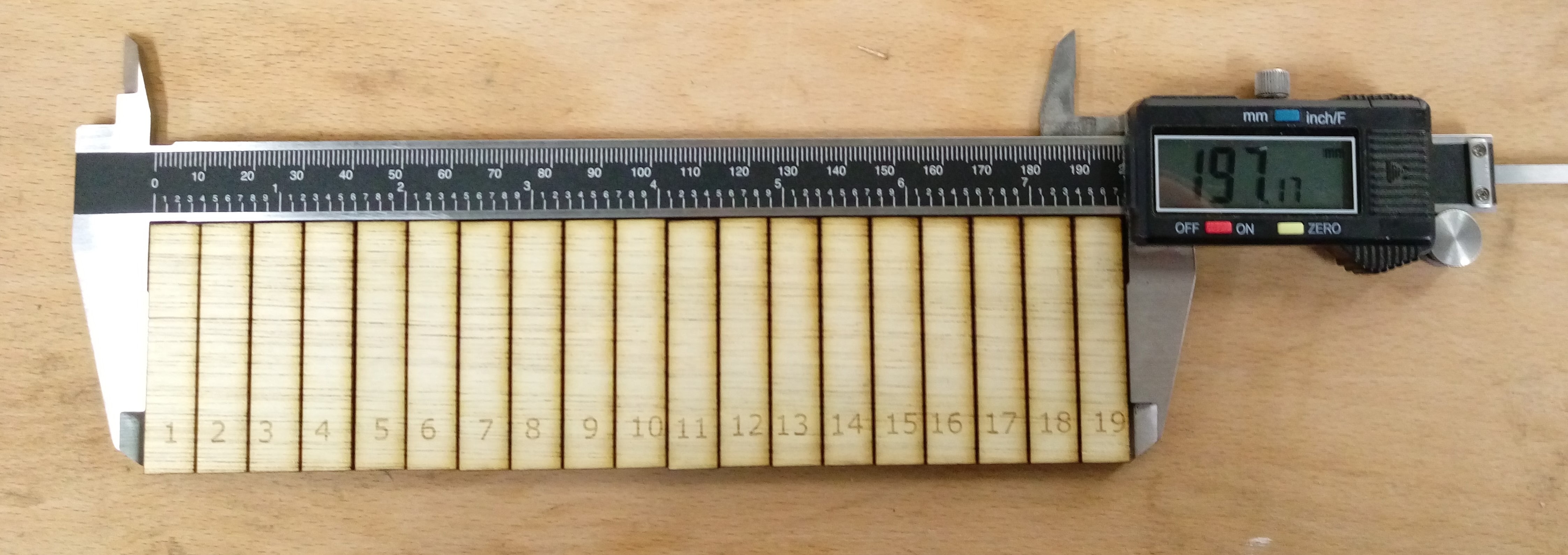
Calculate the kerf
(200-196.71)\20 =0.165
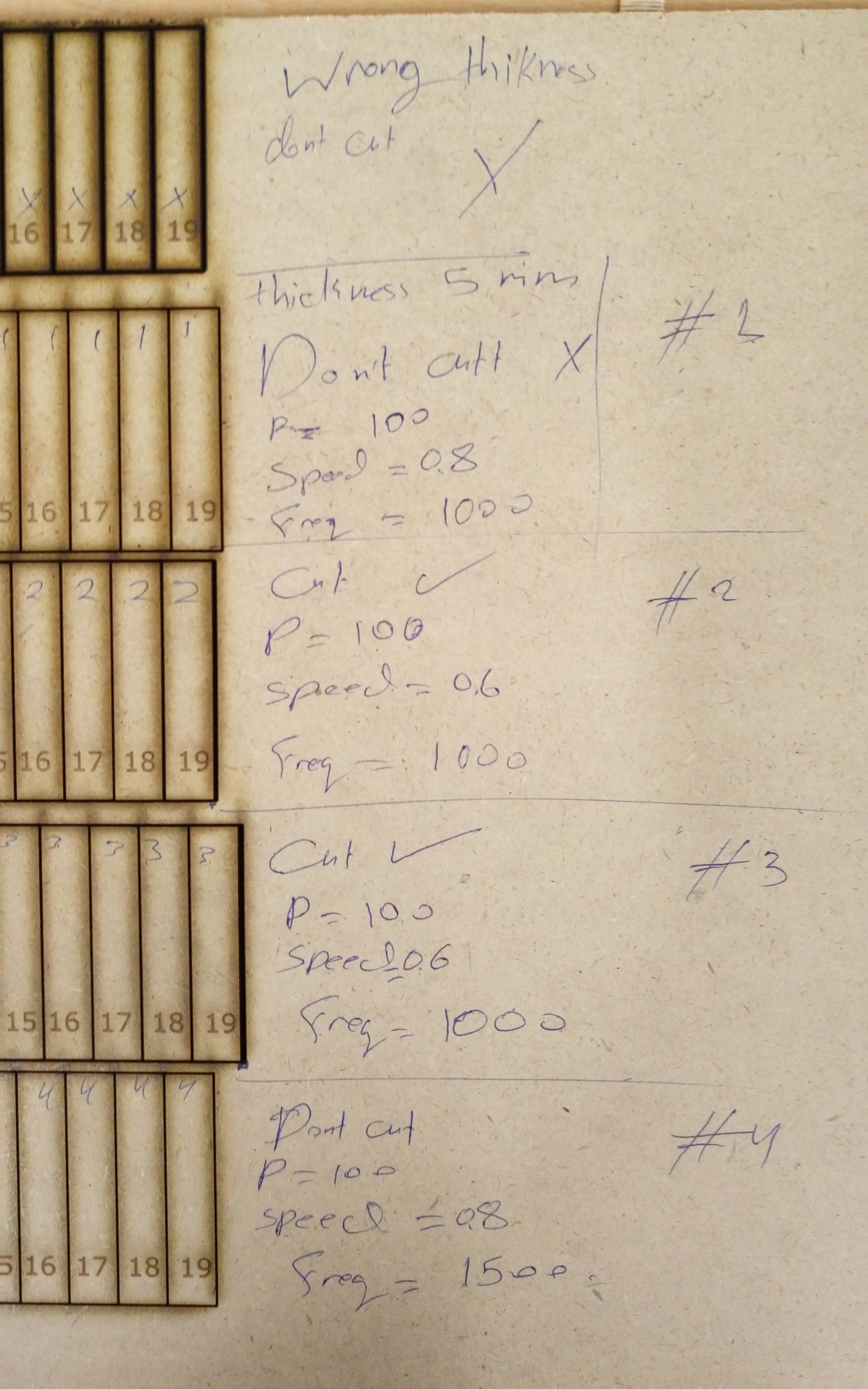
The second test was with MDF wood with 5mm thickness I made 5 tests in the first test I put a wrong thickness so it didn't, also in two of them the machine can't cut the material because the speed was too high.
These photos show the details and results of these tests (But note that in test #3 the correct frequancy is 1500 NOT 1000 )
The mesured distance:

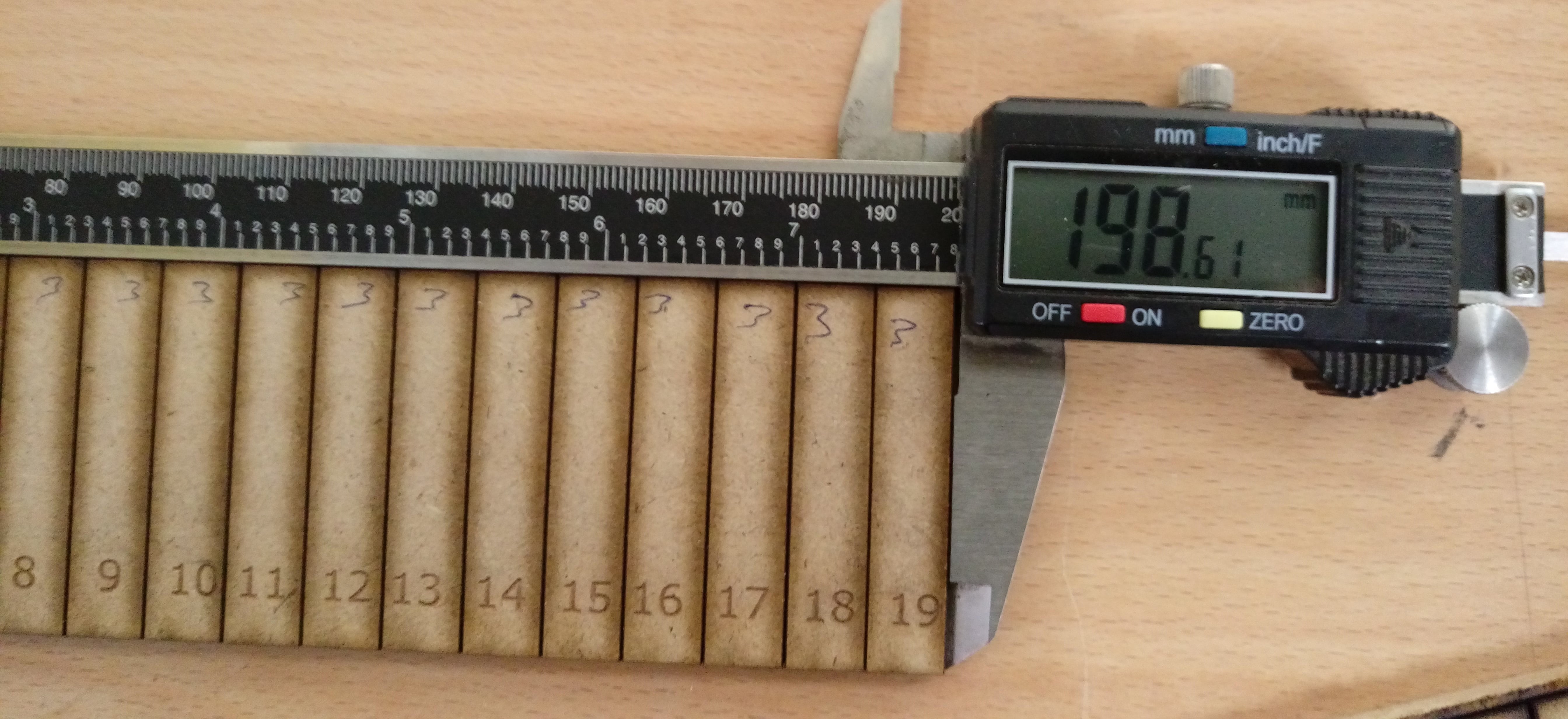
Calculate the kerf for test #2
(200-198.61)\20 =0.07
Calculate the kerf for test #3
(200-198.94)\20 =0.053
So the best settings for 5mm MDF wood is
Power = 100 speed =0.6 Frequency = 1000.
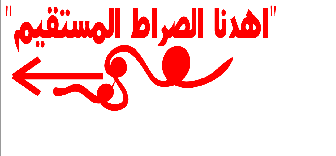
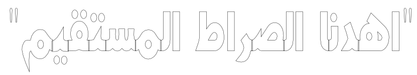
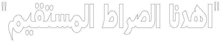
I design a sticker using Inkscape ![]() I decide to design in Arabic language. I choose a phrase from the Holy Quran which mean 'God Show us the straight path'. using
I decide to design in Arabic language. I choose a phrase from the Holy Quran which mean 'God Show us the straight path'. using ![]() icon to write the phrase then edit it' size and font to look like:
icon to write the phrase then edit it' size and font to look like:

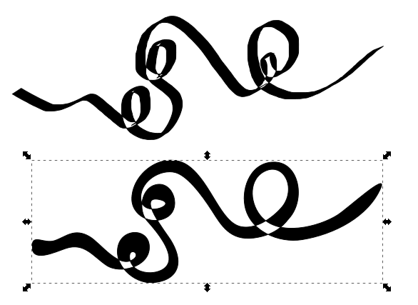
Try to draw some thing looks like A winding crossed road using ![]() icon
icon

Press CTRL+L to make the shape smoother

To remove and edit unwanted node I use 'Edit pathe by nodes '
![]() this will open many tools to edit nodes such as make them smooth, corner, join...etc. So I play with them. The figure shows the first photo with the edited result
this will open many tools to edit nodes such as make them smooth, corner, join...etc. So I play with them. The figure shows the first photo with the edited result
There is still crossing parts should be removed since there is no ' Trim' function in Inkscape. I save the file as use '.dxf' then by Autocad
 command line, firstly, I select the shape ,join lines, trim unwanted lines and finally join again. The result :

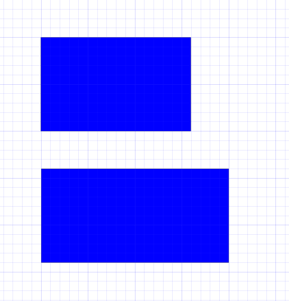
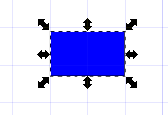
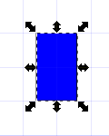
Then to draw an arrow draw three recangular as shown then Union them.
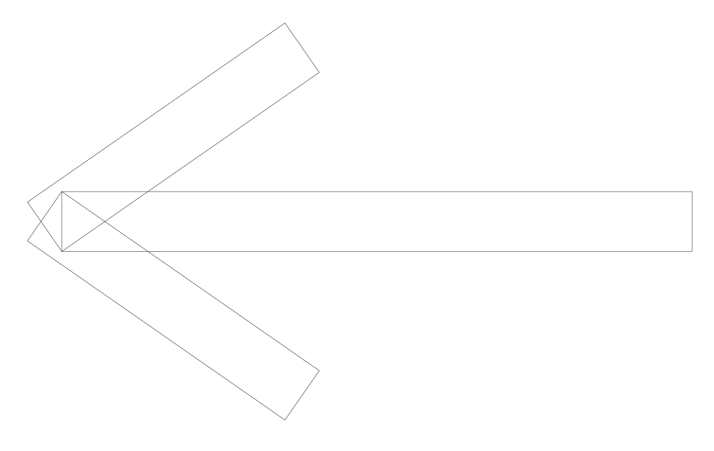
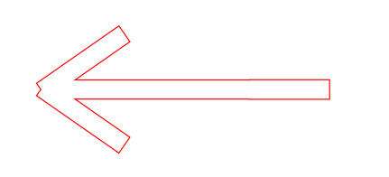
Convert stroke and fill color to Red because our machine cuts red color lines only.Convert stroke line thickness to '0.1' then save file as 'pdf' the file now ready to transfer to Vinyl cutter
The Fab Lab has a Roland Vinyl cutter. First install the wanted material into it then press on it will take a little bit to prepare, then measure the width of the material.
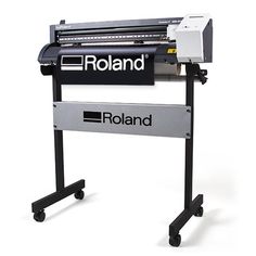
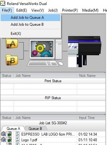
Roland cutter has its own interface software
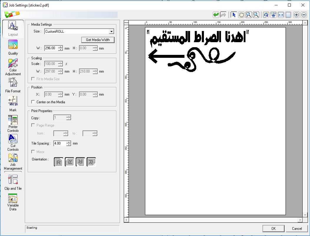
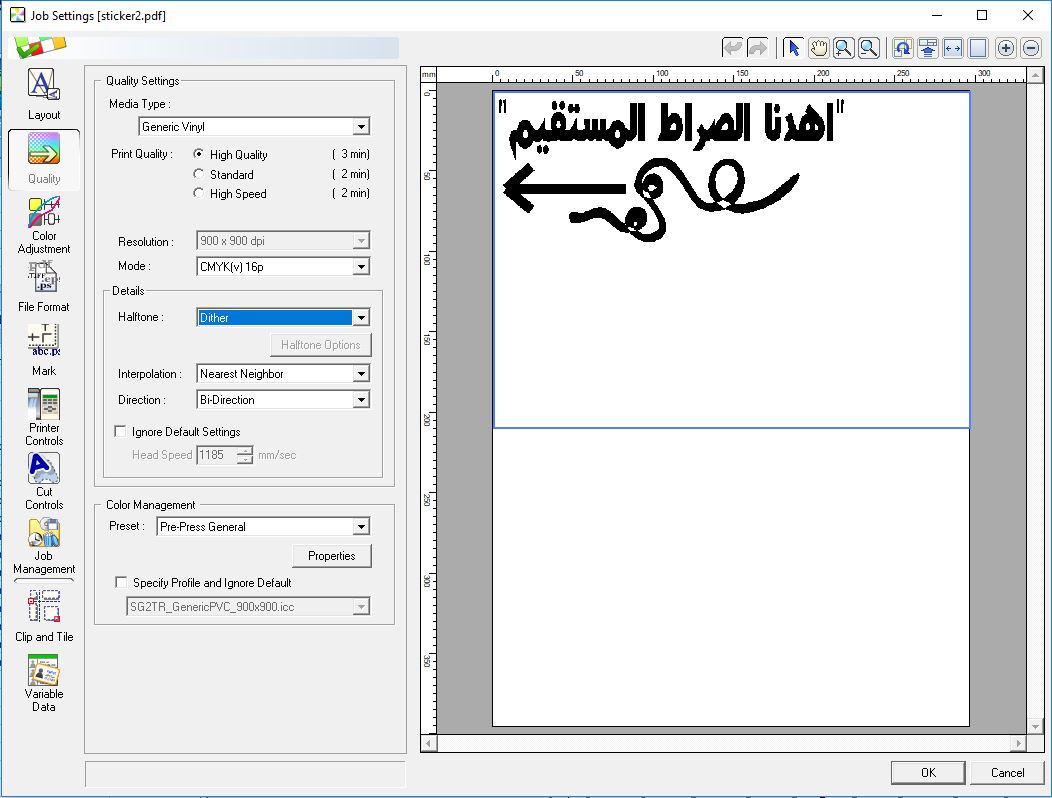
Add My stickers file into it and change settings as shown in figures below then press OK
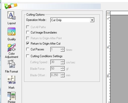
The cut default blade forces '50' was too small I tried to increase it to 60 then 70 finally it quits at 90!.
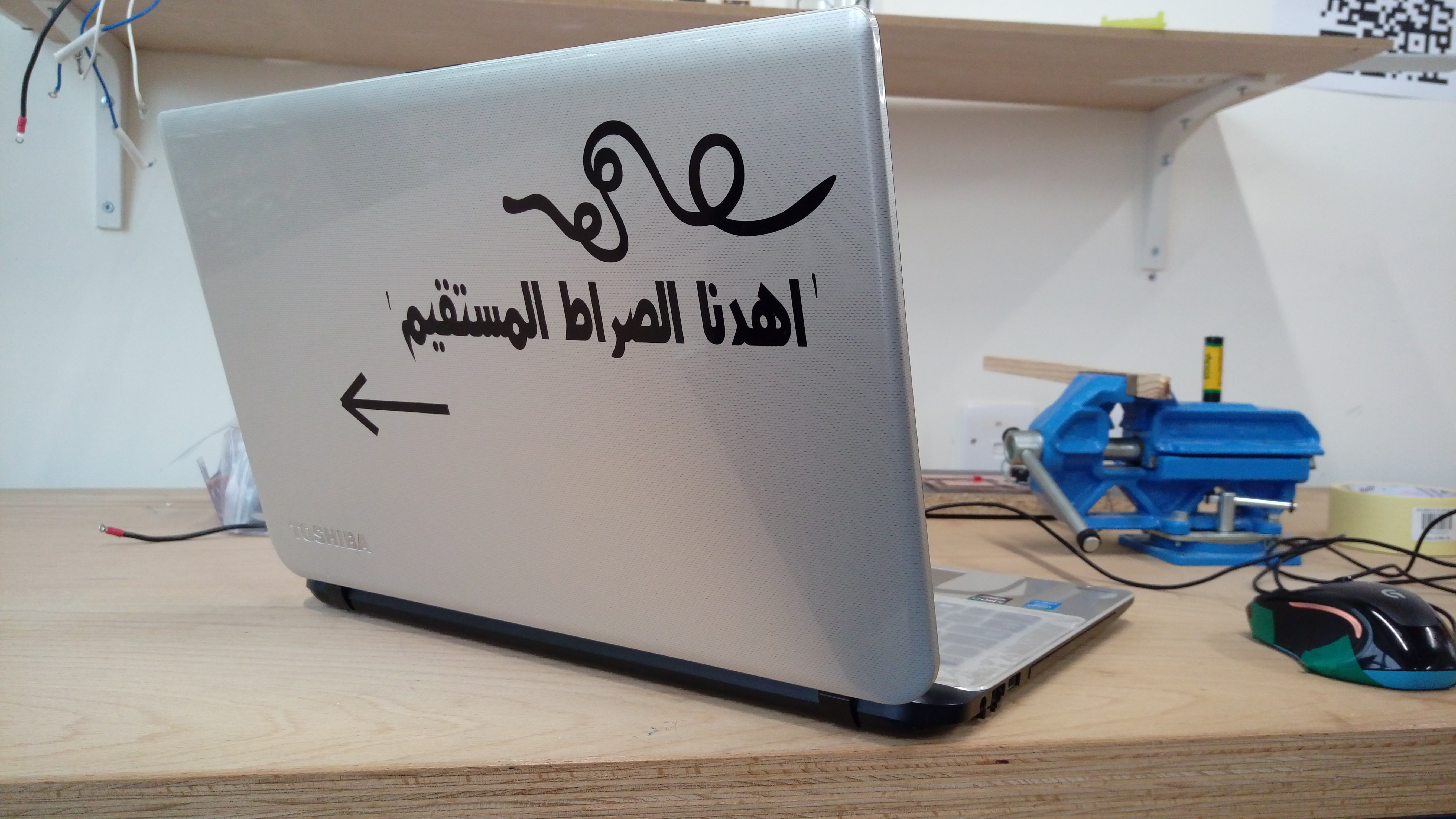
When the machine completed cutting I removed unwanted parts around my sticker then sticked special plaster above it as shown:
Lastly after take off plaster My lapyop become very pretty ^_^
The main problem was writing in Arabic. First, I didn't find any Arabic font among Inkscape fonts so I downloaded them from
HERE
as Zip files just extract and install them so they add automatically to Inkscape.
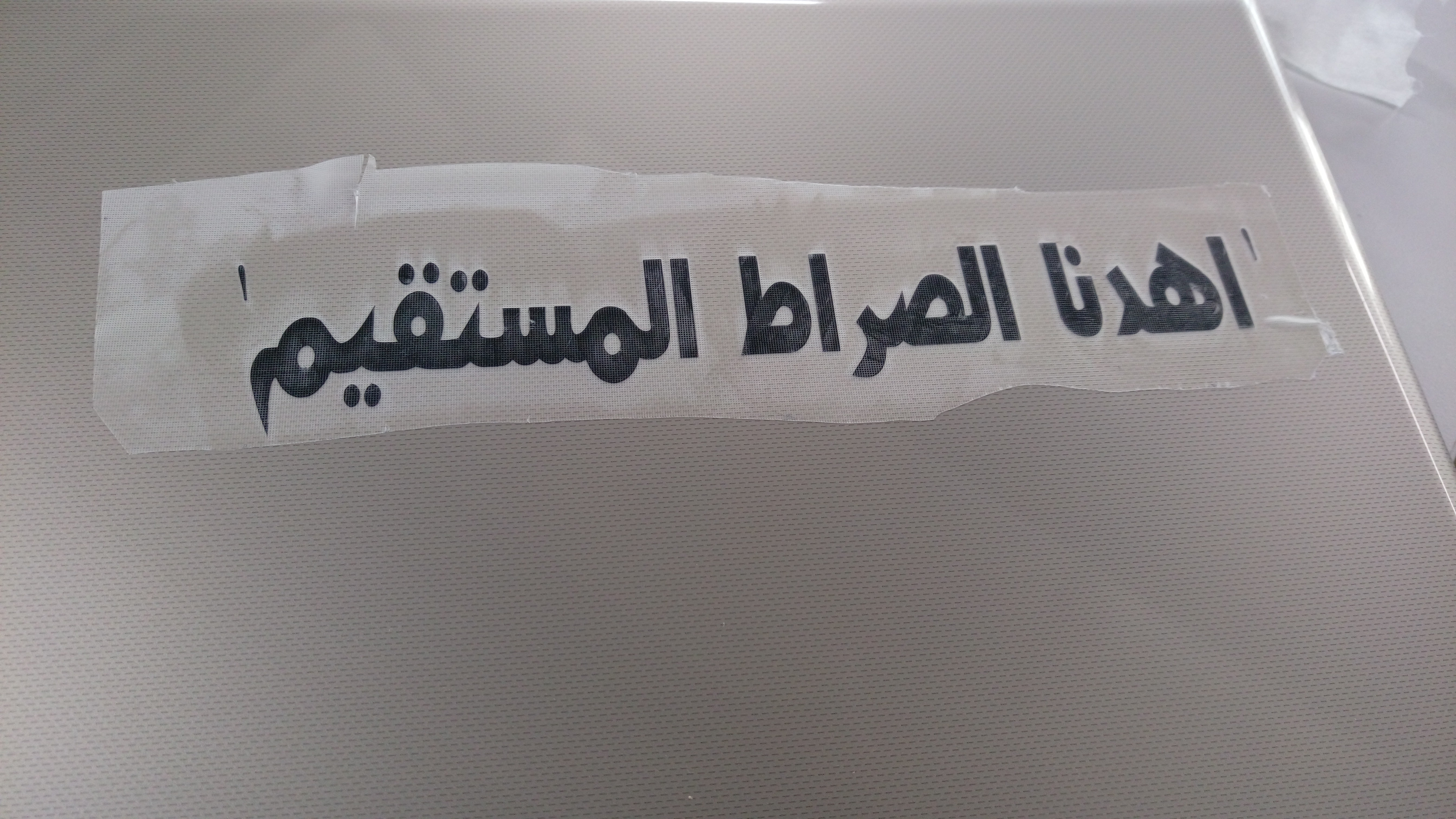
After I found my favorite font I noticed that when convert Arabic font to path using 'Object to path ' tool, it convert each letter separately from others which will cut each letter individually so I could not make correct words.
The problem:
I solved the problem by using 'Combine' command from 'Path' bar. The result:
I will be very happy if you download my sticker
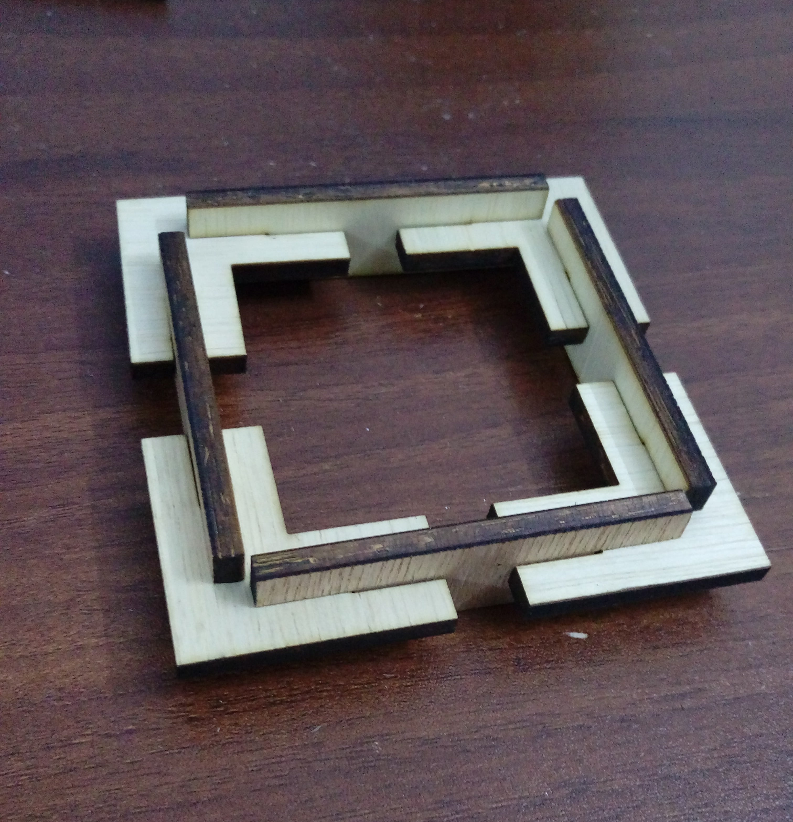
Using Inkscape again to design a box with '10cmX8cmX5cm' start draw the box sides as rectangles with full dimensions
Draw vertical slot with a width equal material thickness '3mm' also draw horizontal slot with hight '3mm' as shown:
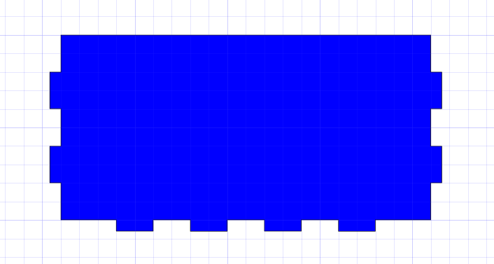
Enable snap to the box corner from snap bar at the right of the screen. Copy slots and arrange them around one face
Use Union command from path bar to connect them together
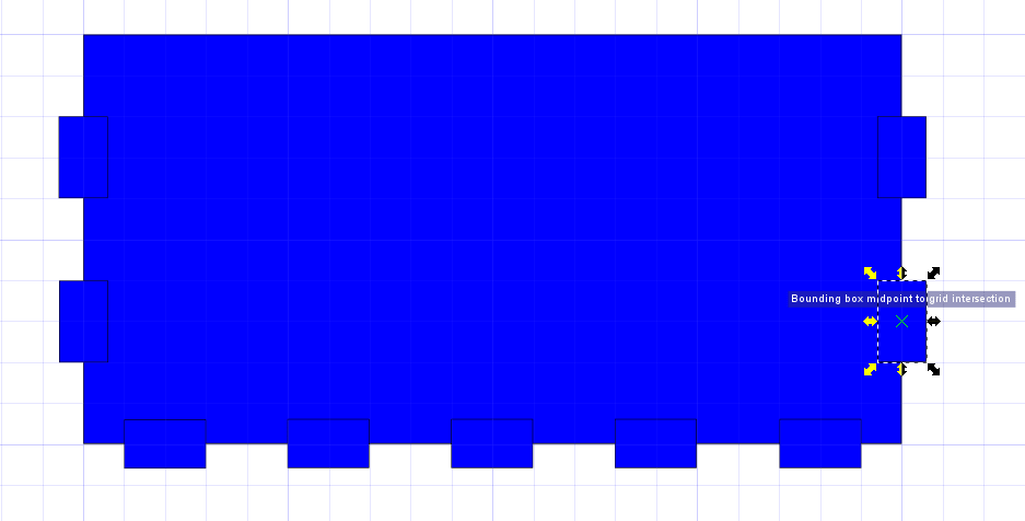
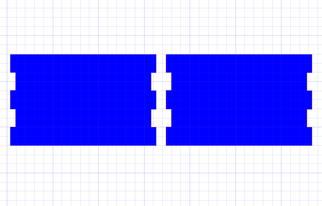
Now copy the previous side and put the other side 'I make it red for clarification' beside it
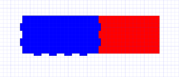
Use Differance command from path bar
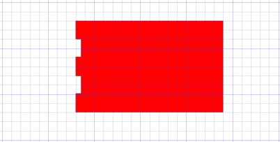
The four sides of the box look like:
Now draw the bottom side as a rectangle
As previous steps use the same slots and arrange them then use Differance command. Make two copies for top and bottom sides
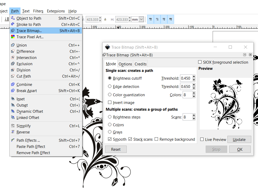
I downloaded this image for internet to put it on the top side of the box then engrave it.

First open the picture from Inkscape, then follow the steps in the figure below to transfer it from pixels to vector Path
.
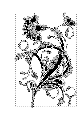
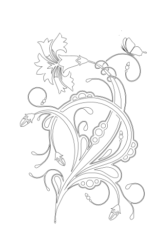
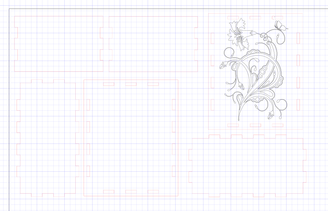
The result nods and paths shown:
All parts before editing to send to the laser cutter
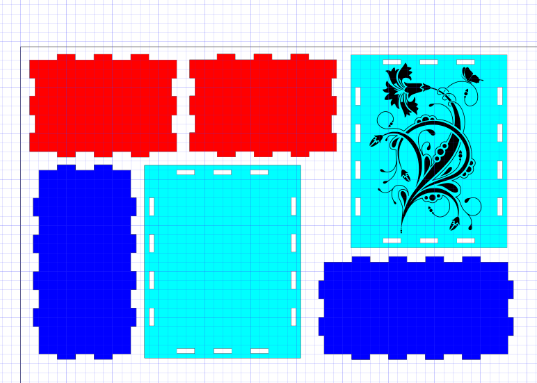
Now make cutting lines Red and engraving lines Black. Also set all stroke line thickness equal '0.1mm'
When the file ready in Inkscape (lines colors and stroke lines thickness(, just press Print and choose the laser cutter name, then the file automatically transfer to JobControl software as shown:
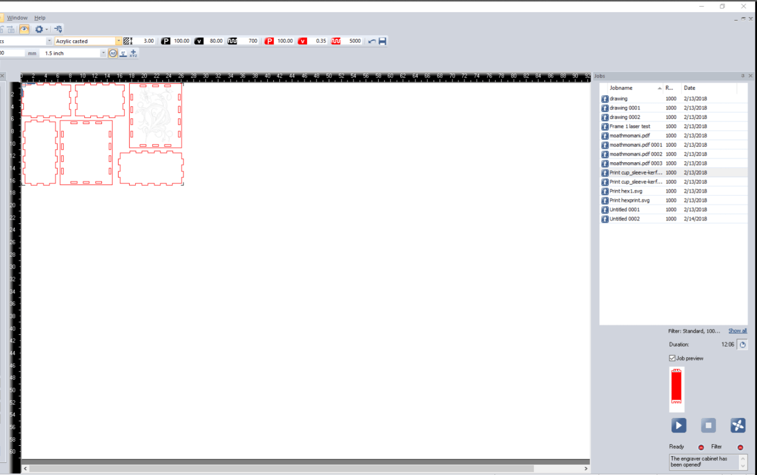
The best settings for plastic are:

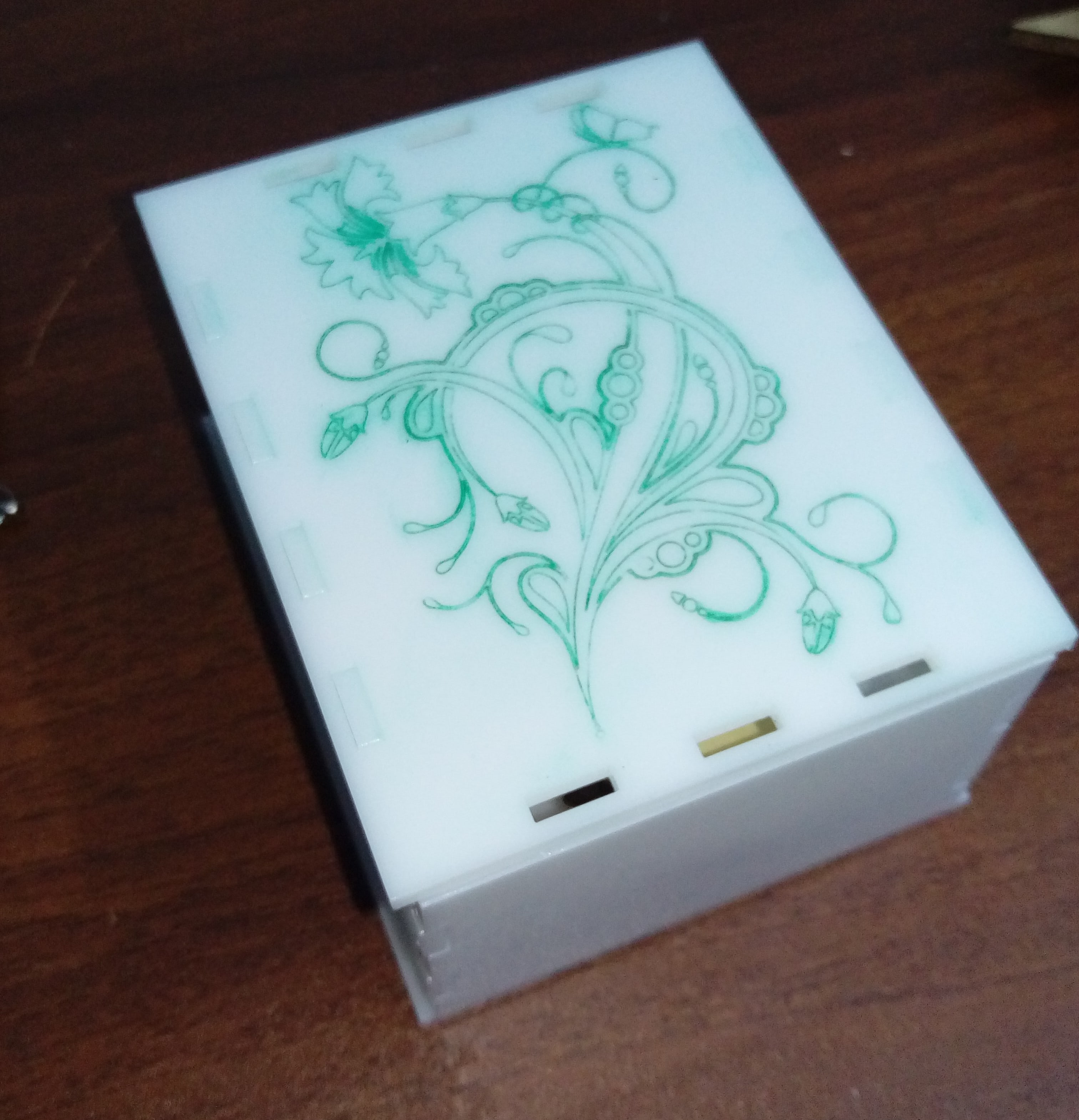
The final assemblyed box 'I just colored graving lines because it is white and can not be seen clearly'
Download files:
Box(.rar)
When I tried to assemble the box faces, they don't fit together firstly I did'n know what is the problem so I transfer all sides to SOLIDWORKS and assemble them so I found the problem which was the dimension of the base it must be taller!.
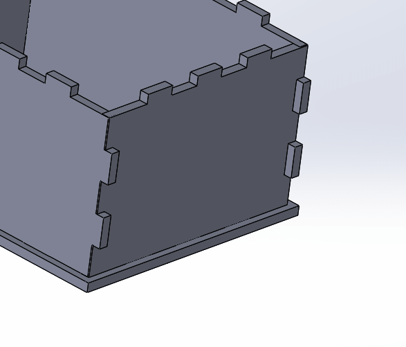
Unfortunately, I could'n edit the dimension after design in Inkscape so I just cut the upper and lower slots from two sides as shown in the figure below. The problem didn't totally solved but at least there is a box now and I can use it. From this work I learned to design on a parametric software then assemble the design before fabricate it.
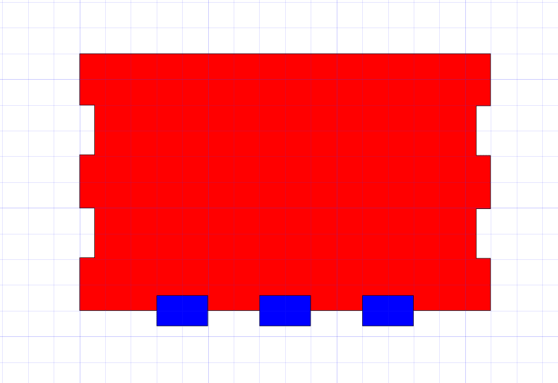
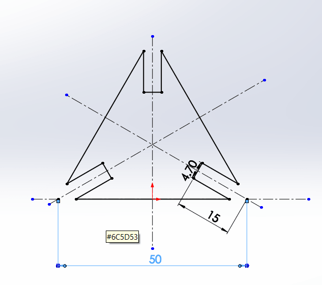
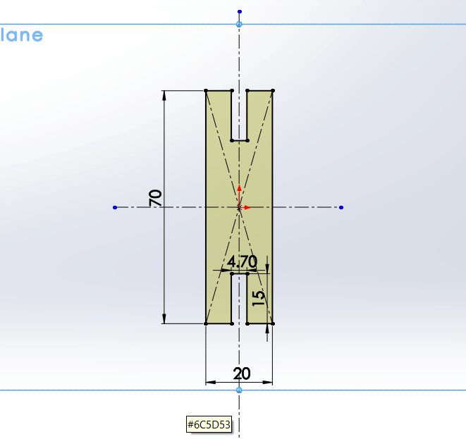
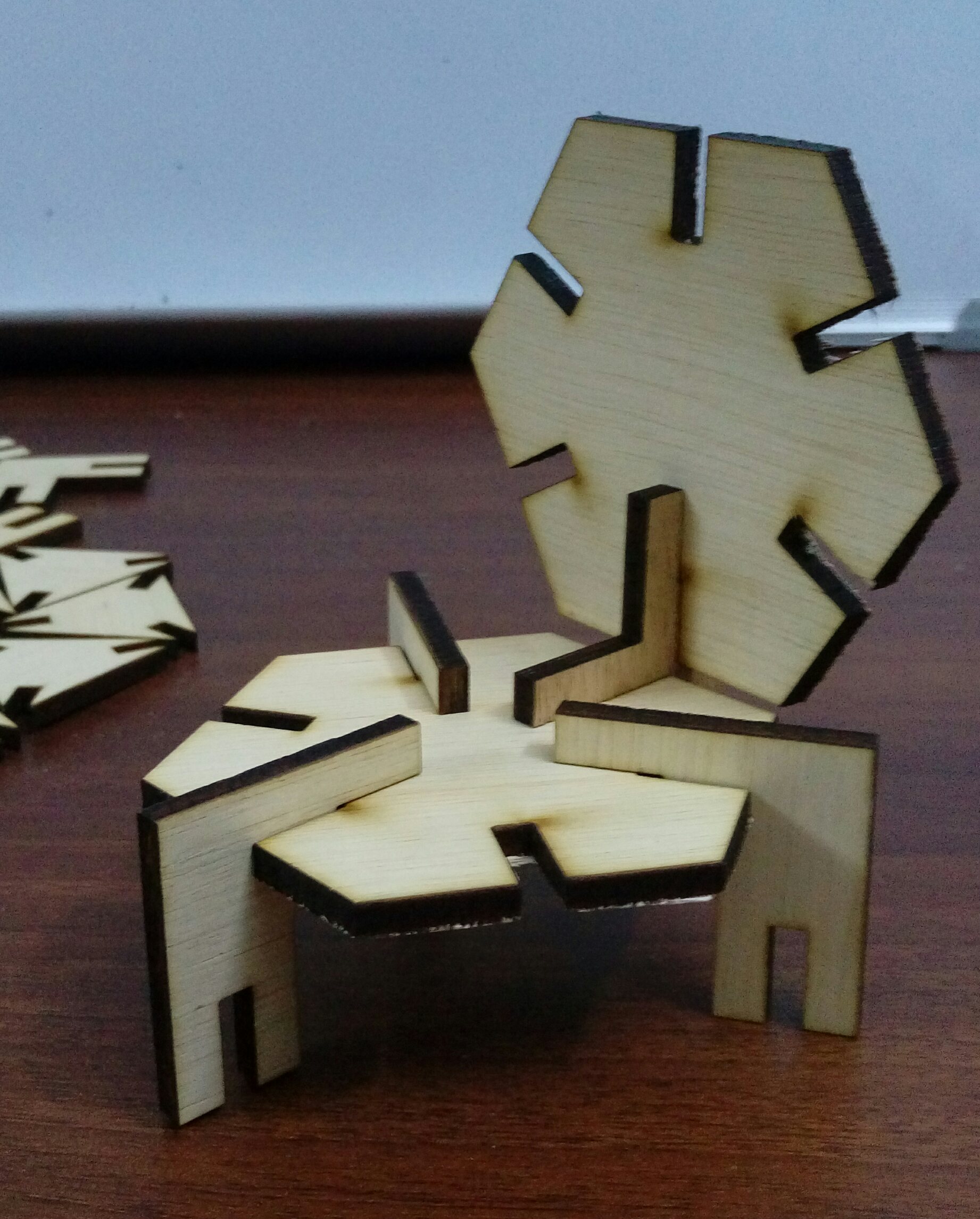
I used SOLIDWORKS to design and test many shapes of puzzle pieces. Start with the first sketch to draw a hexagonal shape using ![]() icon, then draw a slot inside it
icon, then draw a slot inside it
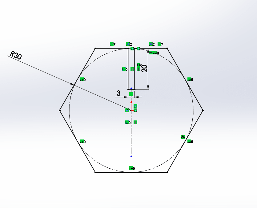
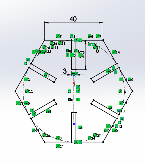
Use ![]() icon to make six slots around the shape
icon to make six slots around the shape
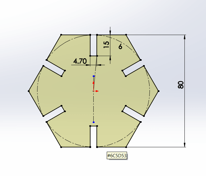
After I finished my design I recognized that there is no 3mm thickness wood so because I used a parametric software I could easily change all slots dimensions by one click. Also
To use the power of parametricity on SOLIDWORKS, I decided to define a number of variables so if the material I'm using is changed I could easily change these numbers and the design will automatically change! it is a kind of magic!!.
The variables: Thick:represent the thickness of the material.
Kerf :represent the kerf which depend on the used material.
Slot:equation to find the slot dimension which is Thik- 2*Kerf.
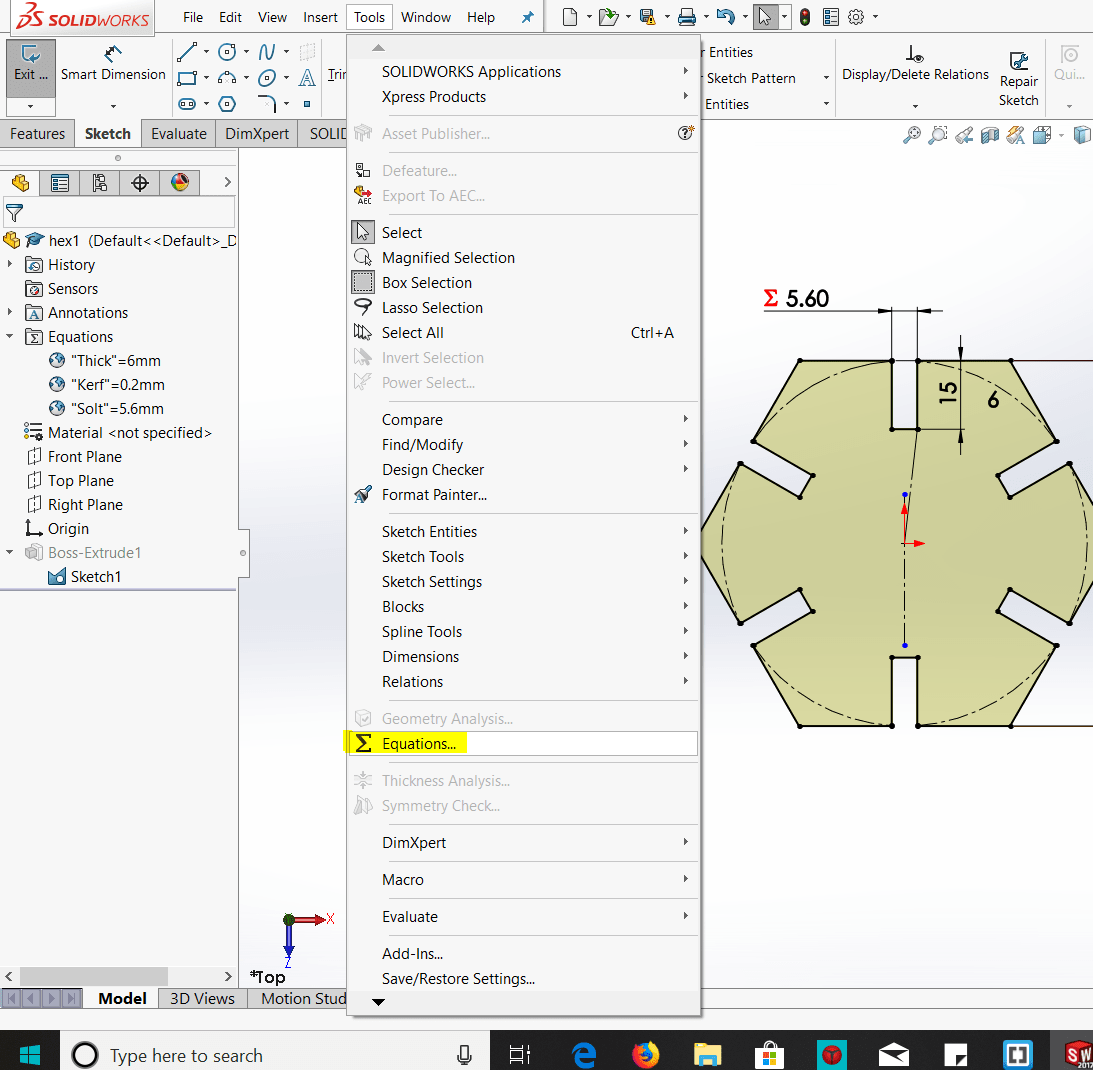
To define that variables I select Equations as shown:
Then I wrote the variables in Global Variables and pressed on Link to external file and created a new file.
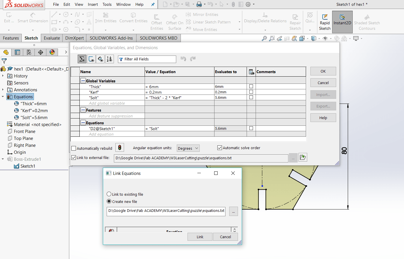
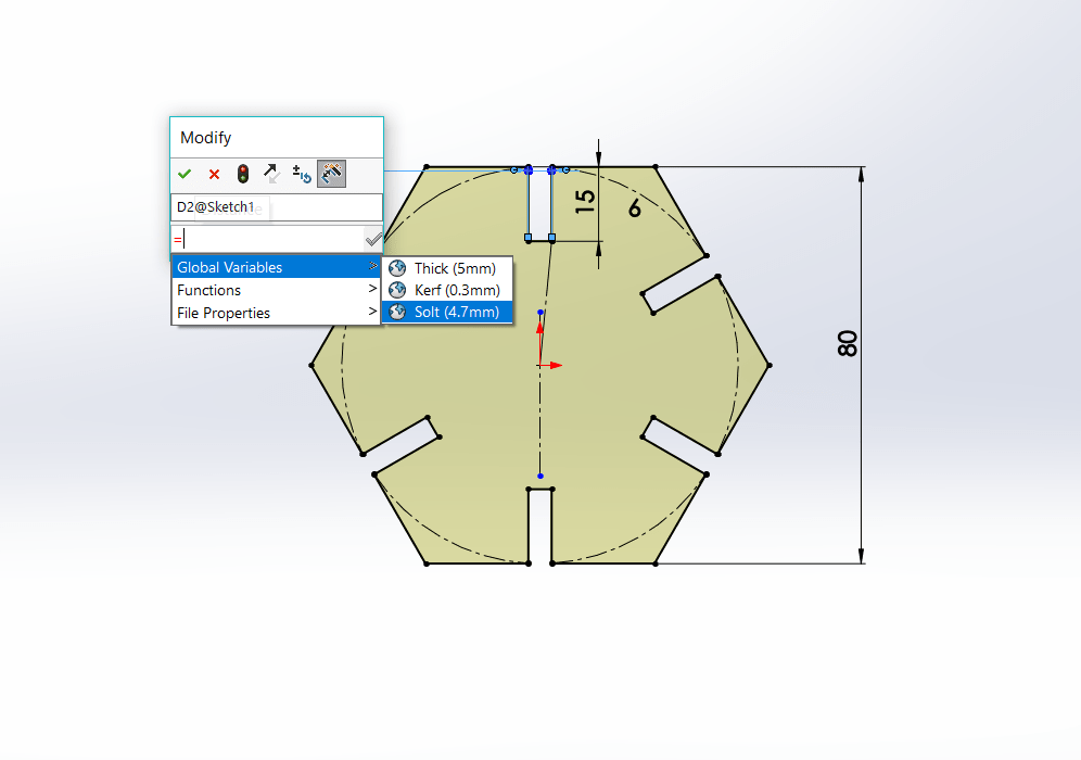
After that, back to the sketch and link slot dimension to the global variable Slot as shown:
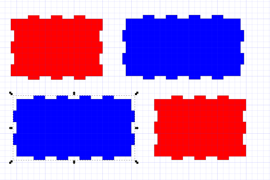
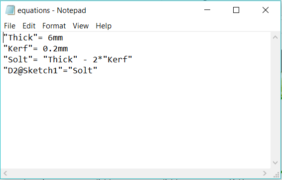
Now assume that I want to use a material with 6mm thickness and 0.2mm kerf. I will simply open the text file that I linked my equation to it. There I will find the variables I defined:
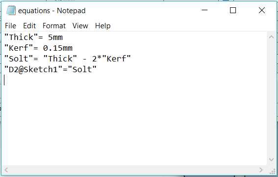
Then I will change variables to the new values:
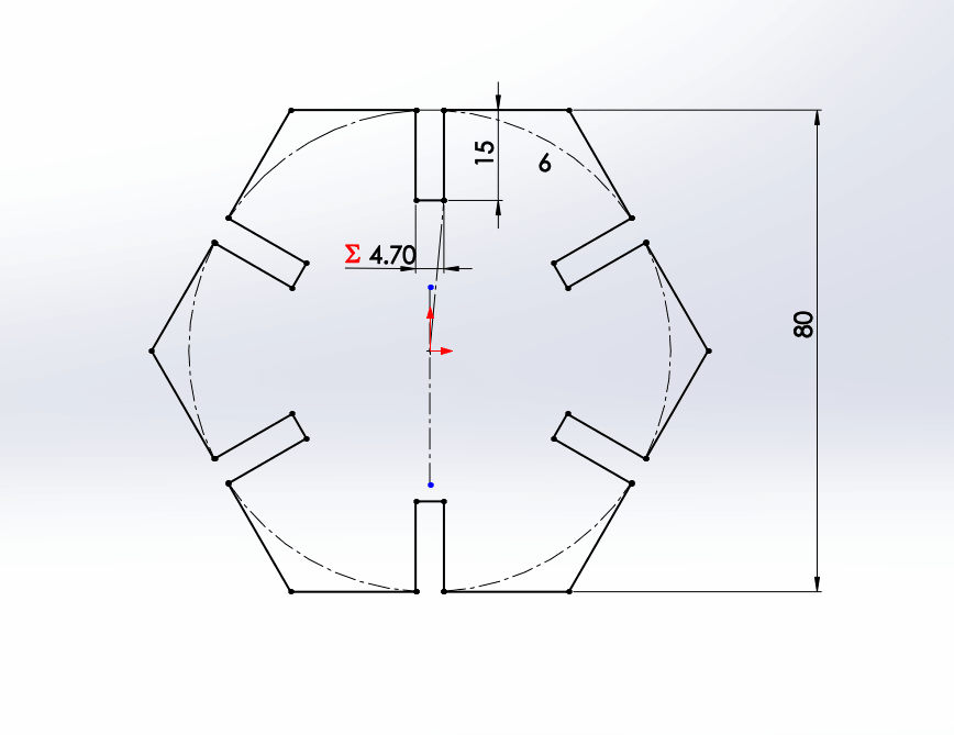
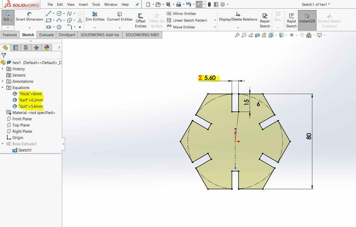
Then I will save the text file, back to SOLIDWORKS press on rebuild and the whole design will change as shown:
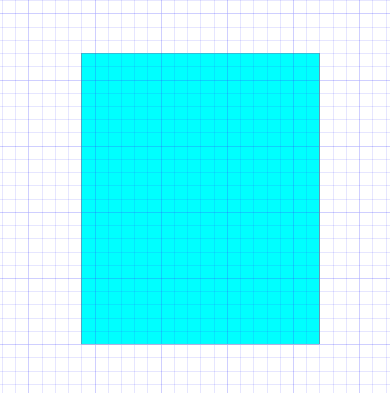
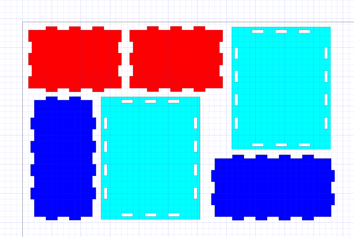
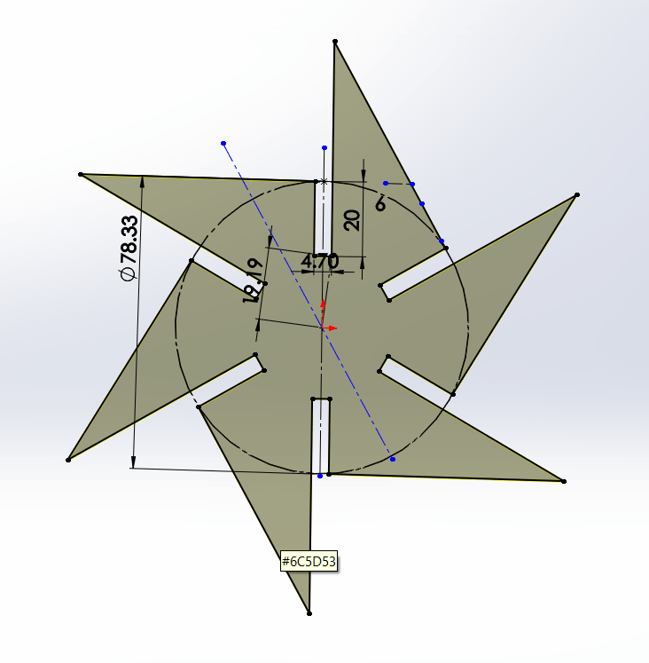
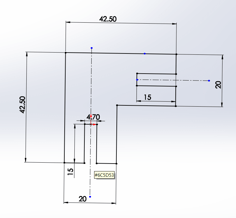
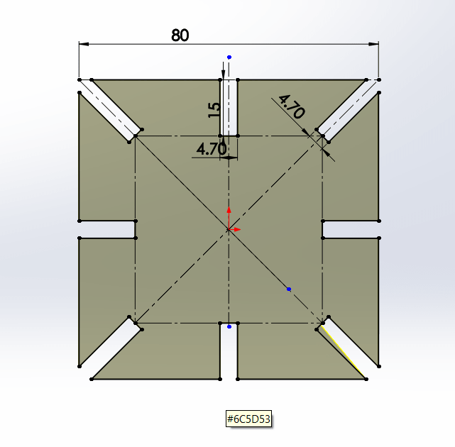
I designed many other pieces of my 3D puzzle
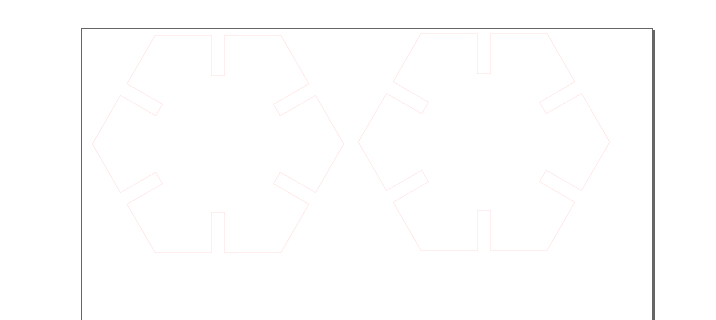
Now save previous sketches as '.DXf' then open them by Inkscape edit colors and thickness as previous section then print them to laser JobControl software.The first printed parts shown in figure:
In JobControl select Plywood material with these settings:

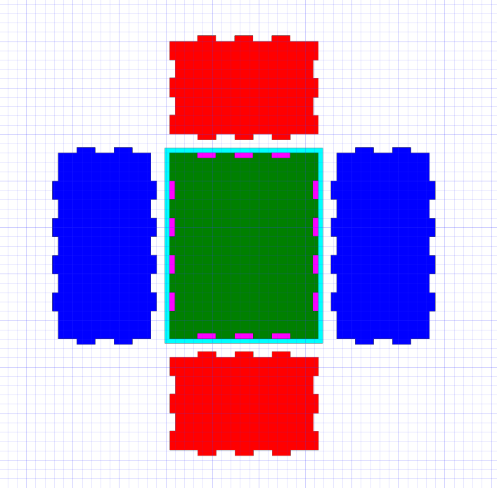
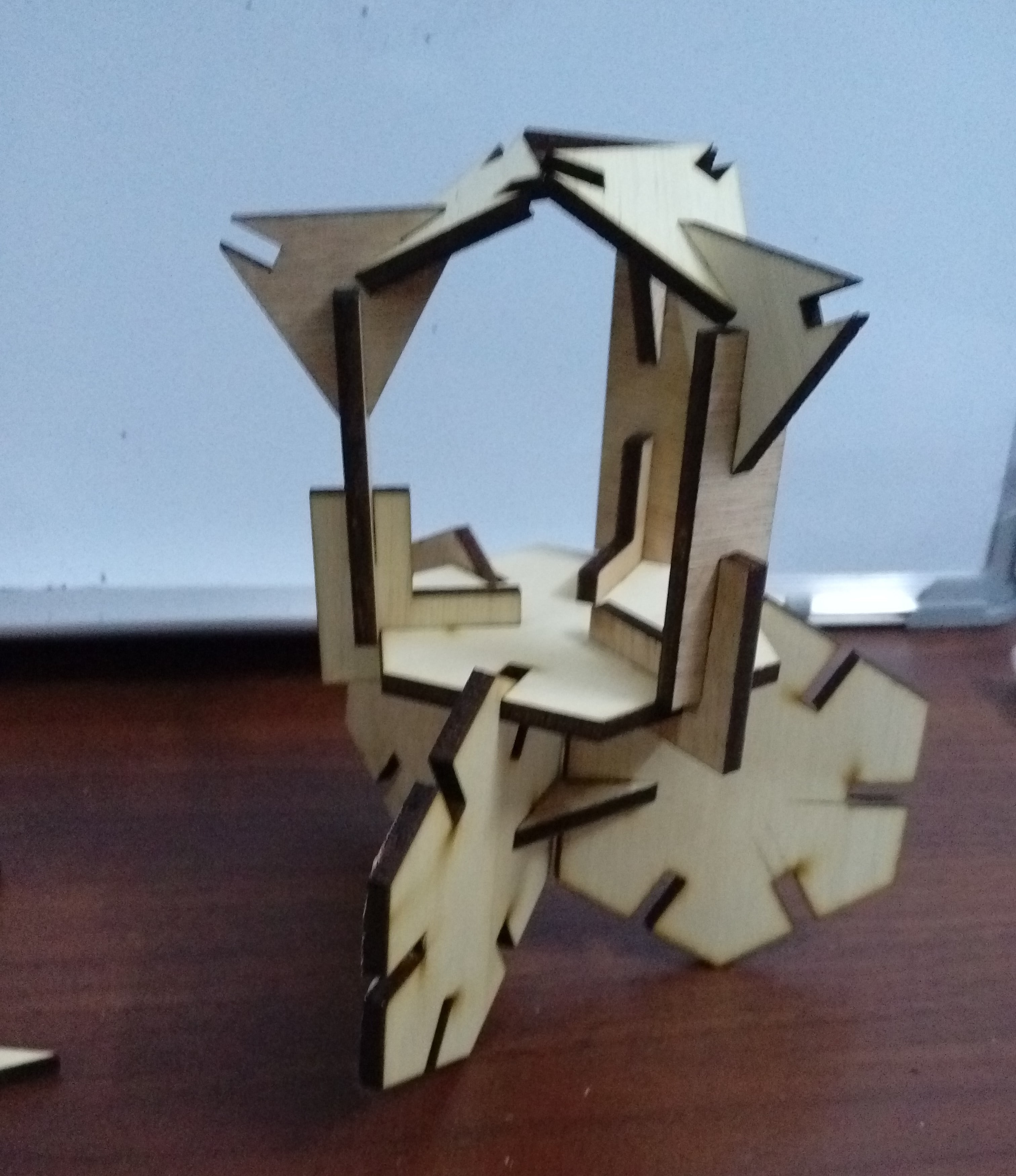
All my puzzle parts and some of shapes made by them:
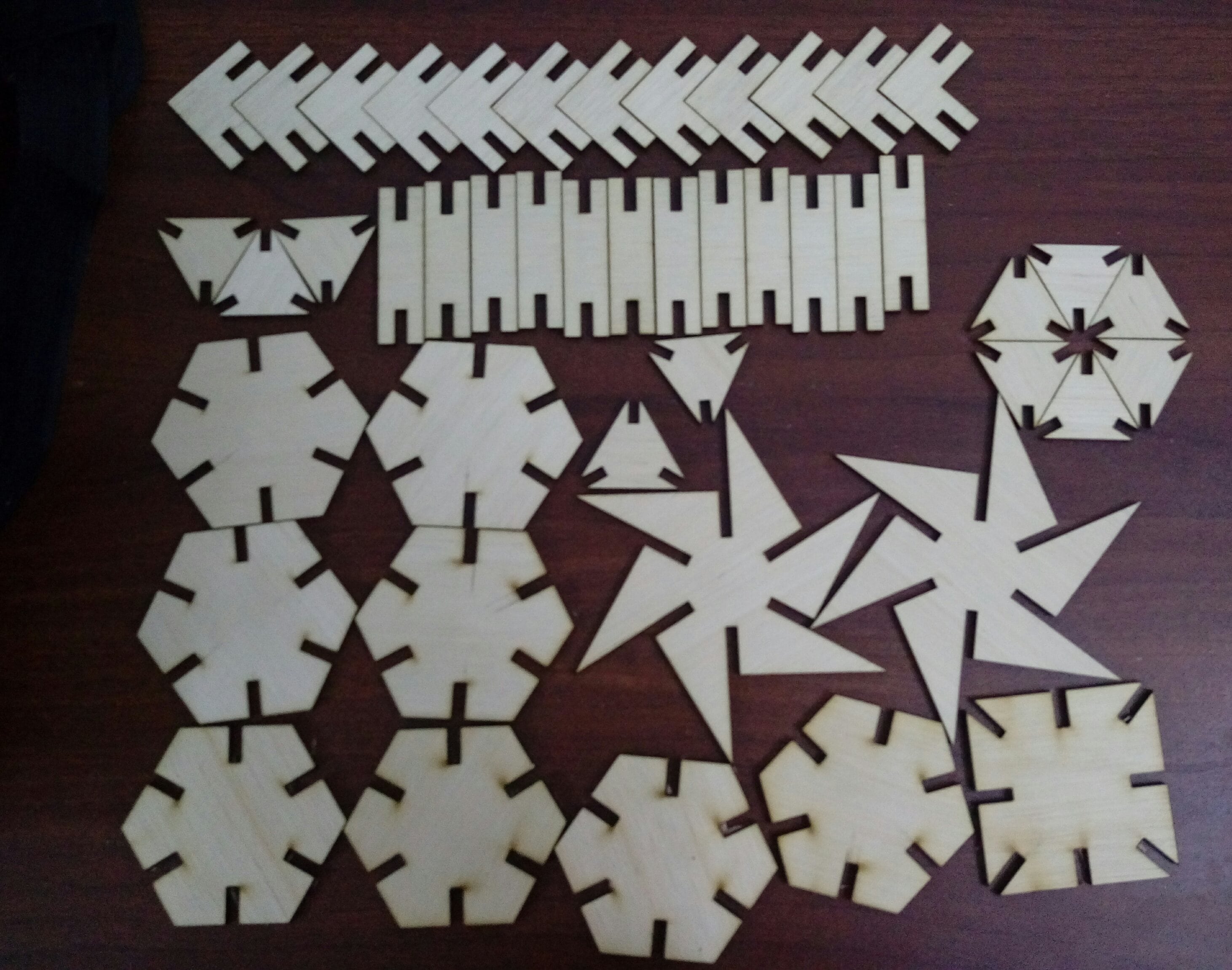
Download files as DXF
puzzle(.rar)
The first problem was the loose in the joint I solved it by decreasing slot width from 5 to 4.7mm.
The second problem was twisting in the wood plate so the machine couldn't cut the pieces I tried to fix the plate on the machine bed also I decreased cutting speed.