In this page I will document my own work in the two week group project of machine building. These weeks were mechanical design and machine design. You can find the full group documentation in
the group page.
The idea
We want to build a Qatayef Machine. Qatayef is an Arabic traditional pastry like pancake. Usually it is made in the holy month of Ramadan.
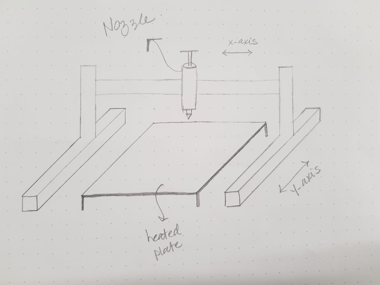
After we made a discussion of what component we have in the lab and how we could effectively use them, we decided the main concept of the machine axes. The brief sketch of the machine drawn by creative Eng.Nadine. As shown in the sketch we have a fixed heated plate in the middle ,two motors carries Y axis and one motor moves in X axis and carries the extruder which also has a motor to move in Z axis to extrude the paste.
Mechanical Design
Y axis Design
As a mechanical engineer with some experience of how CNC machine works and designs I started the design process as I mentioned before,in our design we have a fixed plate which will carry the heater, so the Y axis should carry X axis and extruder. I know this design will lead to high weight so high torque on Y axis motors, but unfortunately we have no choice because we couldn't move the plate that carry heaters.
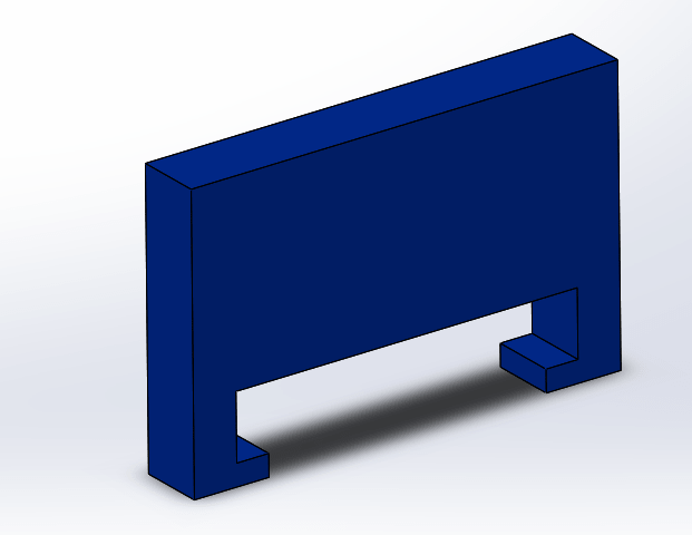
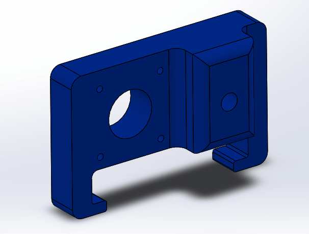
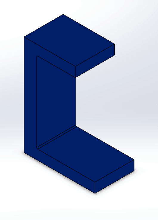
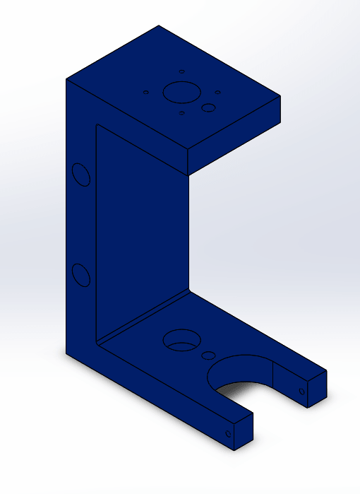
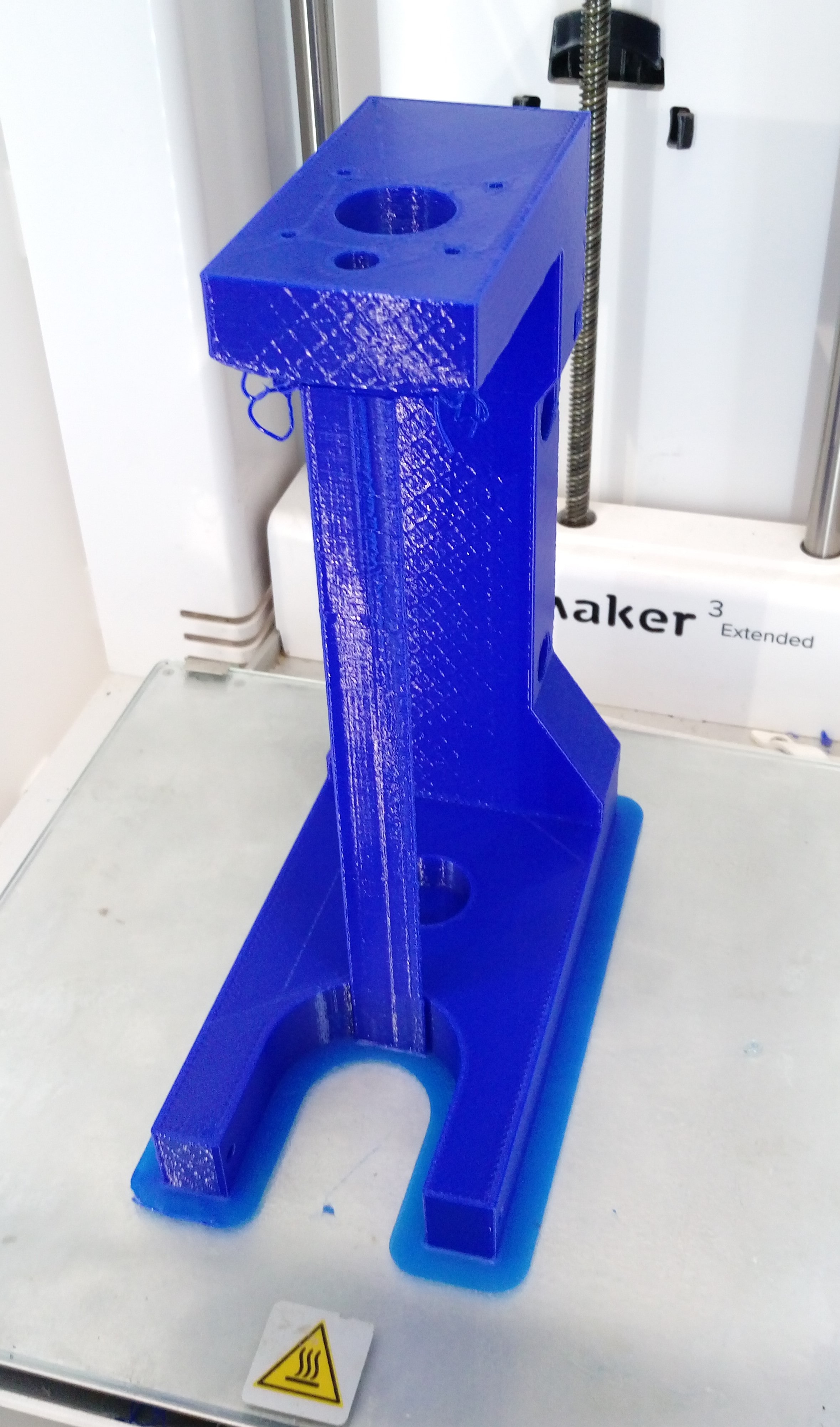
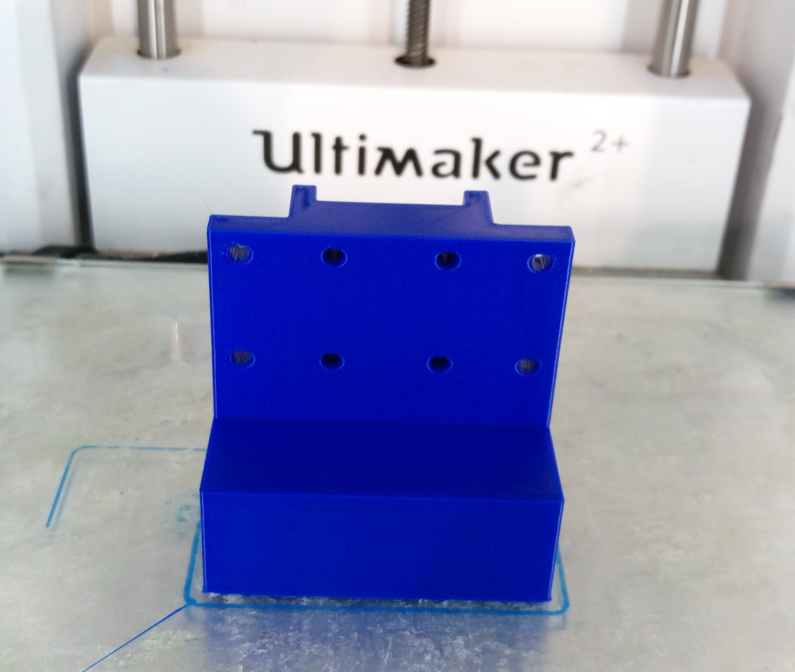
We already have T slot 4x8 and 4x4 mm aluminum profile which will carry Y axis mechanism. I choose a stepper motor with lead screw mechanism in each side of the Y axis. I started by download CAD designs for : Nema 17 stepper motor, 5x8mm coupler, lead screw and bearings from GRABCAD library, then I designed two parts using Solidworks. The first part to hold the stepper motor :
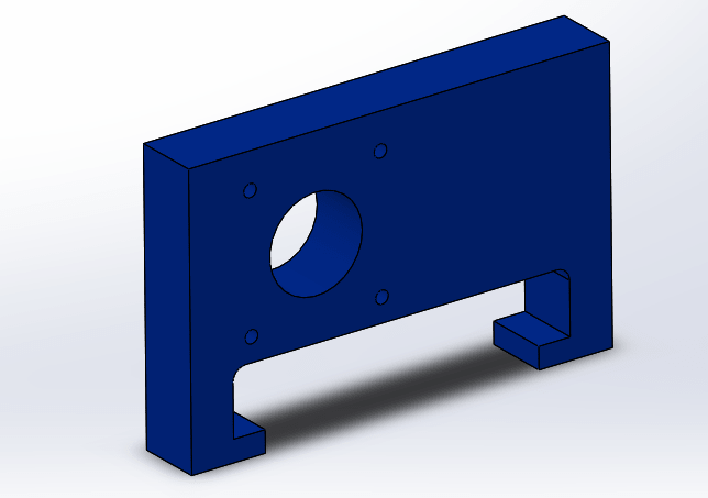
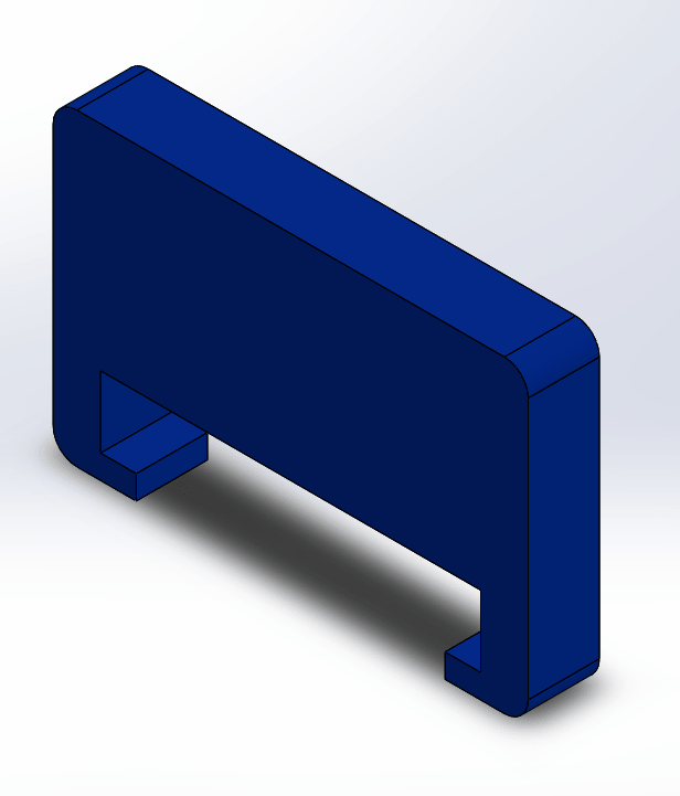
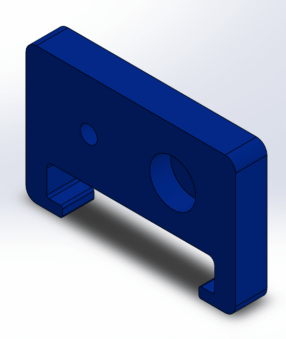
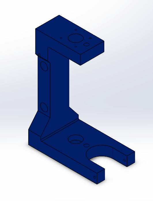
The second part on the other side of Y aixe to hole the lead screw and the guide rod:
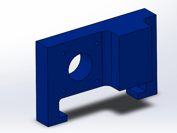
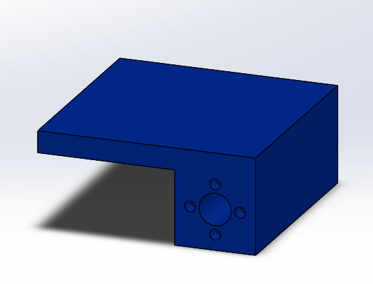
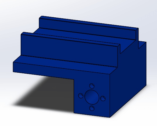
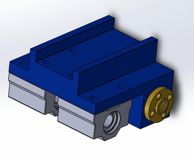
Also I designed a block connected lead screw nut and bearing this block should carry X axis component.
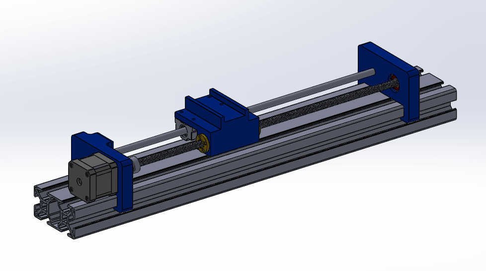
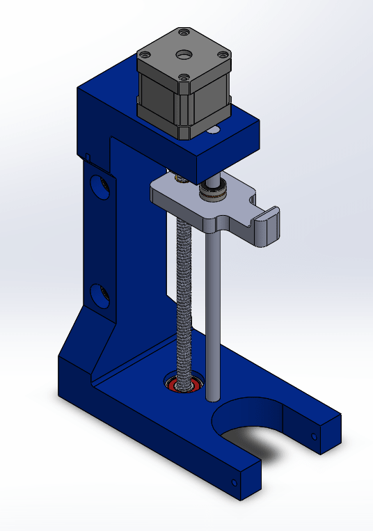
After that I assemble all parts on the T-slot profile in one assembly file shown:
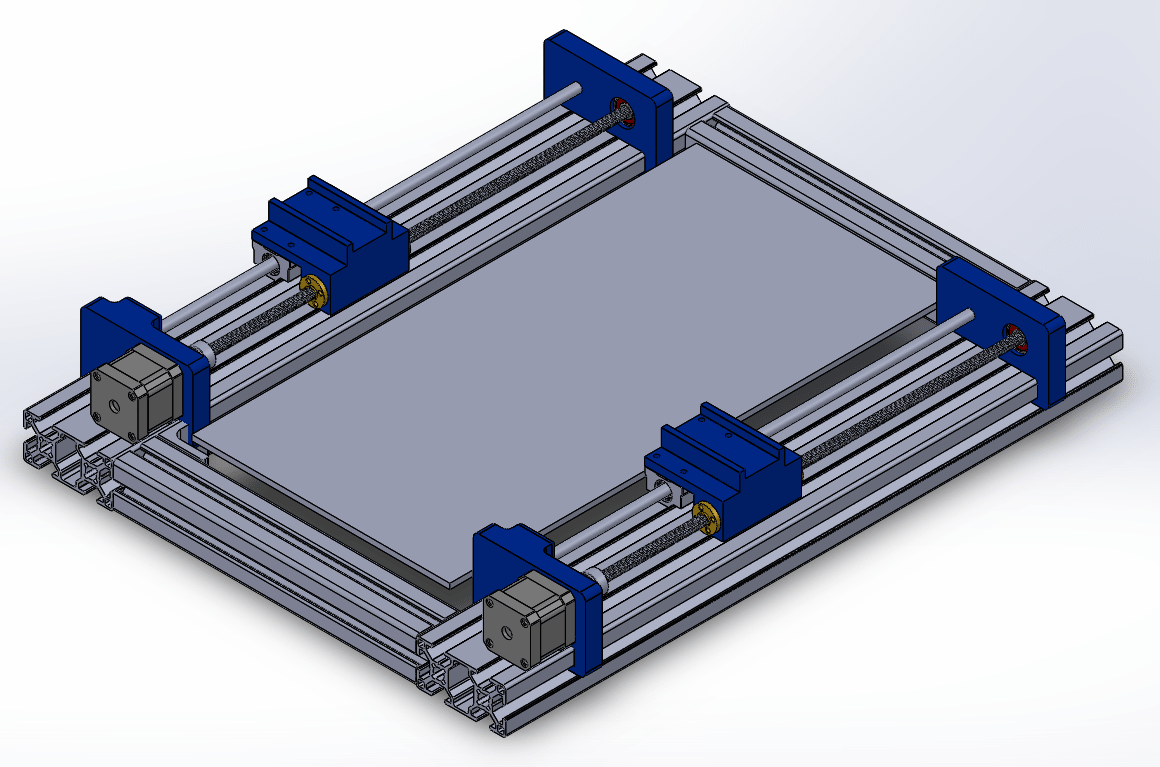
The assembly of the Y axis and the plate:
Extruder Design
Our awesome team members designed the X axis and Extruder based on my Y axis design. But because Extruder is a critical part we decide to make two separated designs and try them both to see which will be the optimal design.
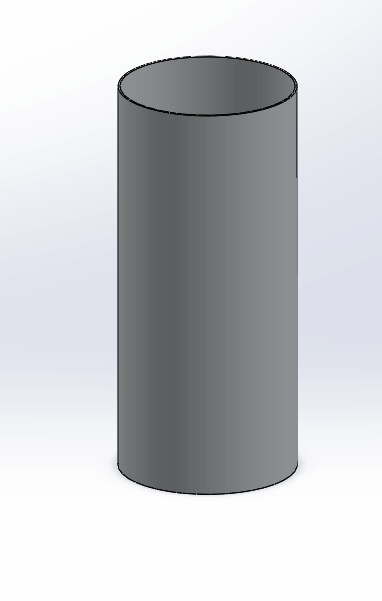
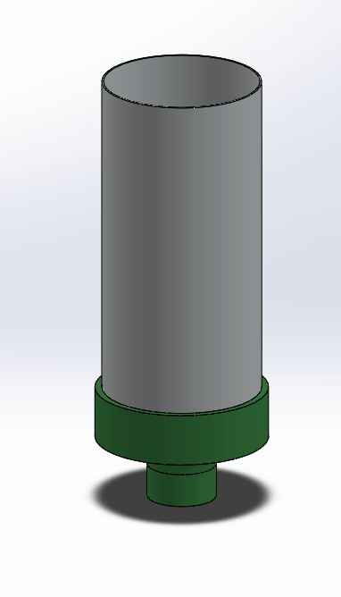
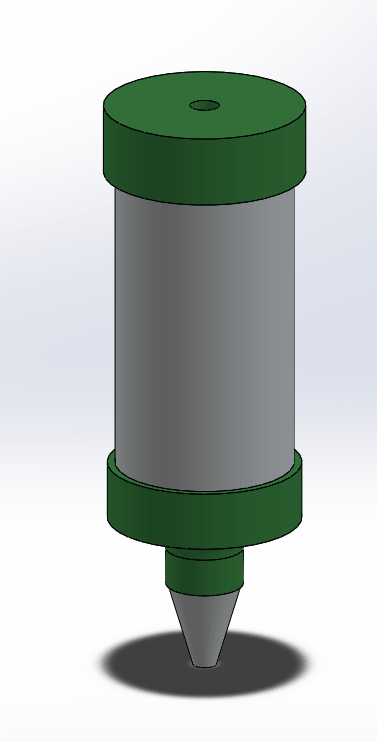
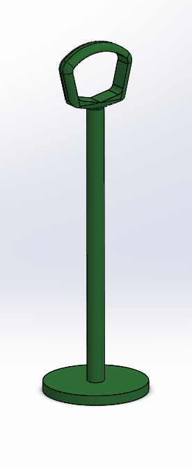
We bought a nozzle and I measured and draw it to make sure that the design will fit with the nozzle.
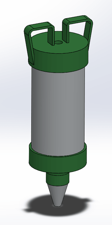
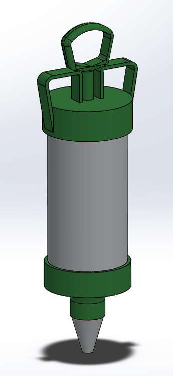
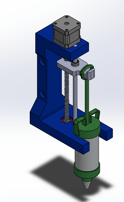
I started to design the main part of the extruder, then added all parts in one assembly:
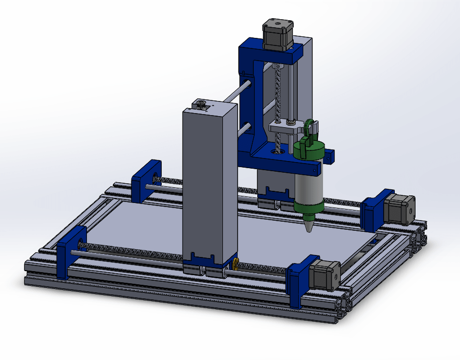
After all team members finish their designs, this is the approximation appearance of our machine:
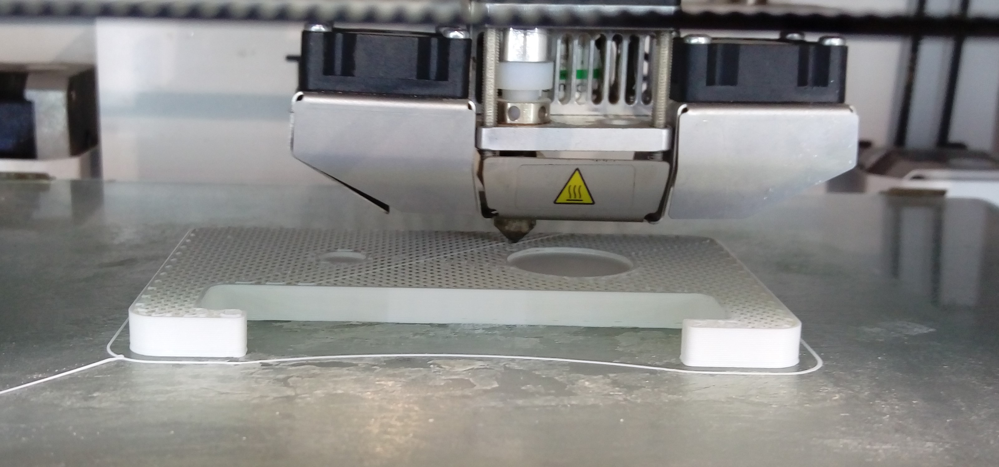
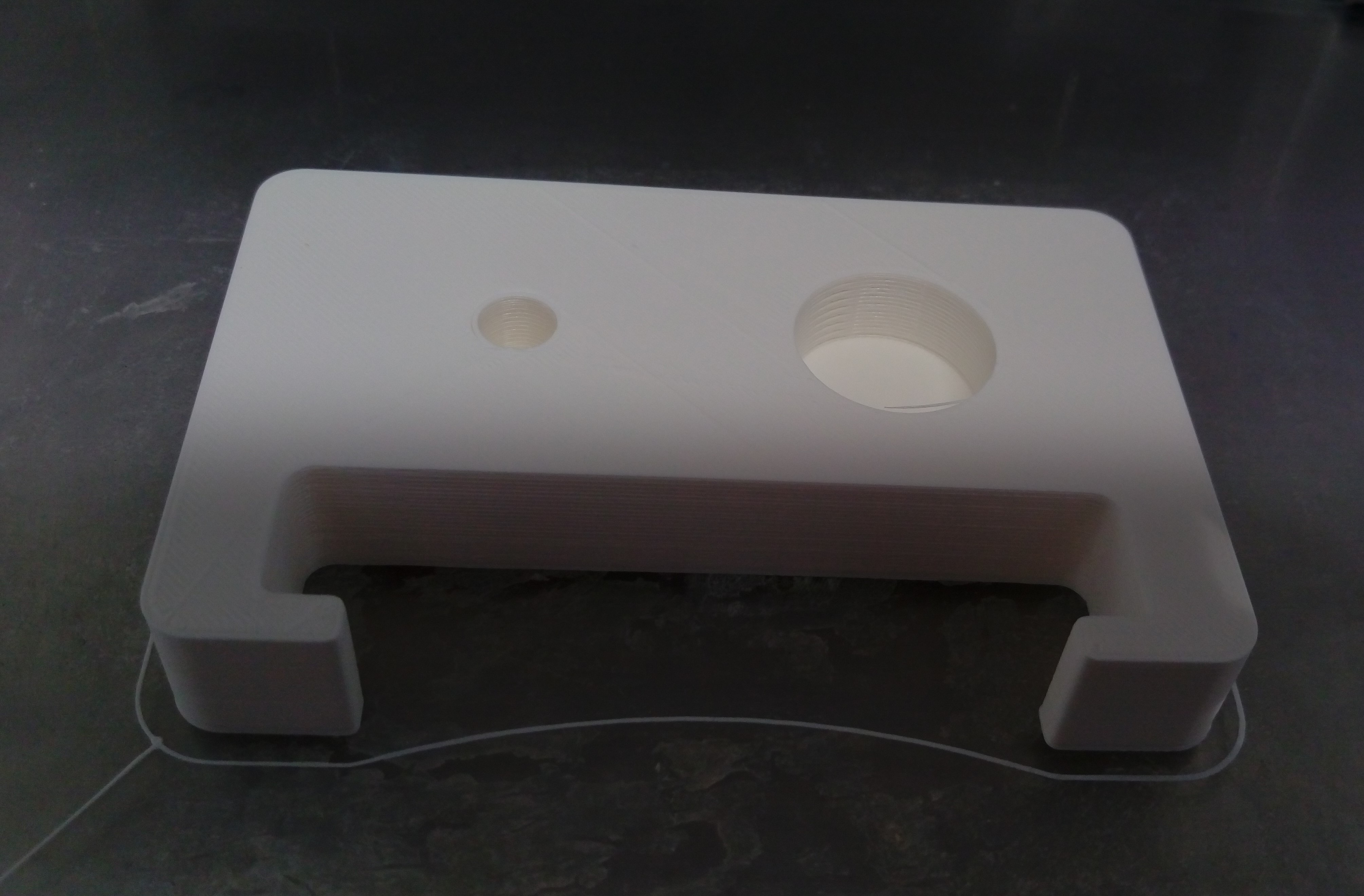
3D Printing of Designed Parts
We bought some of mechanical parts such as linear bearing and leas screw nuts, others was already in the lab such as stepper motors. Also, we 3D printed the most of rest parts, our 3D printing expert Qusai Malahmeh select the best settings of them. Some pictures of printing opjects:
Problems in Design and Assembly
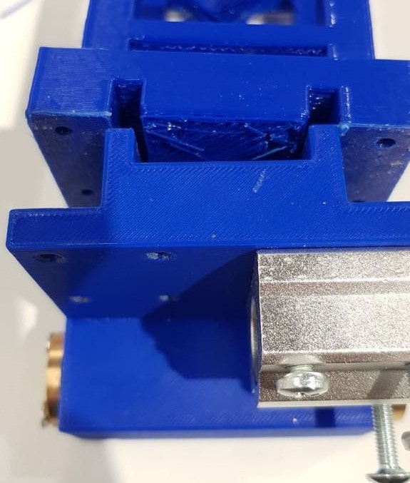
One of the major problems I faced was the precision of 3D printed objects. The parts that should fit together in assembly actually didn't fit. as shown in the figure.
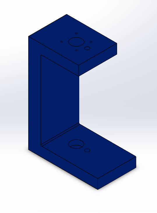
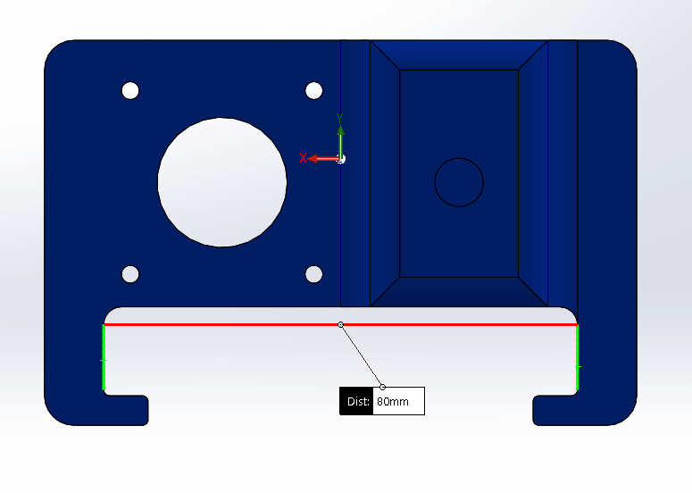
For example, when I designed the steeper motor holder of Y axis I made the inner distance exactly 80 mm as shown below, to fit on T slot profile which has 80mm outer dimension. After we print it, I noticed that the part couldn't fix on the T slot because the actual inner dimension was smaller than designed one, so we manually sanded them with different file shapes until they fit together.
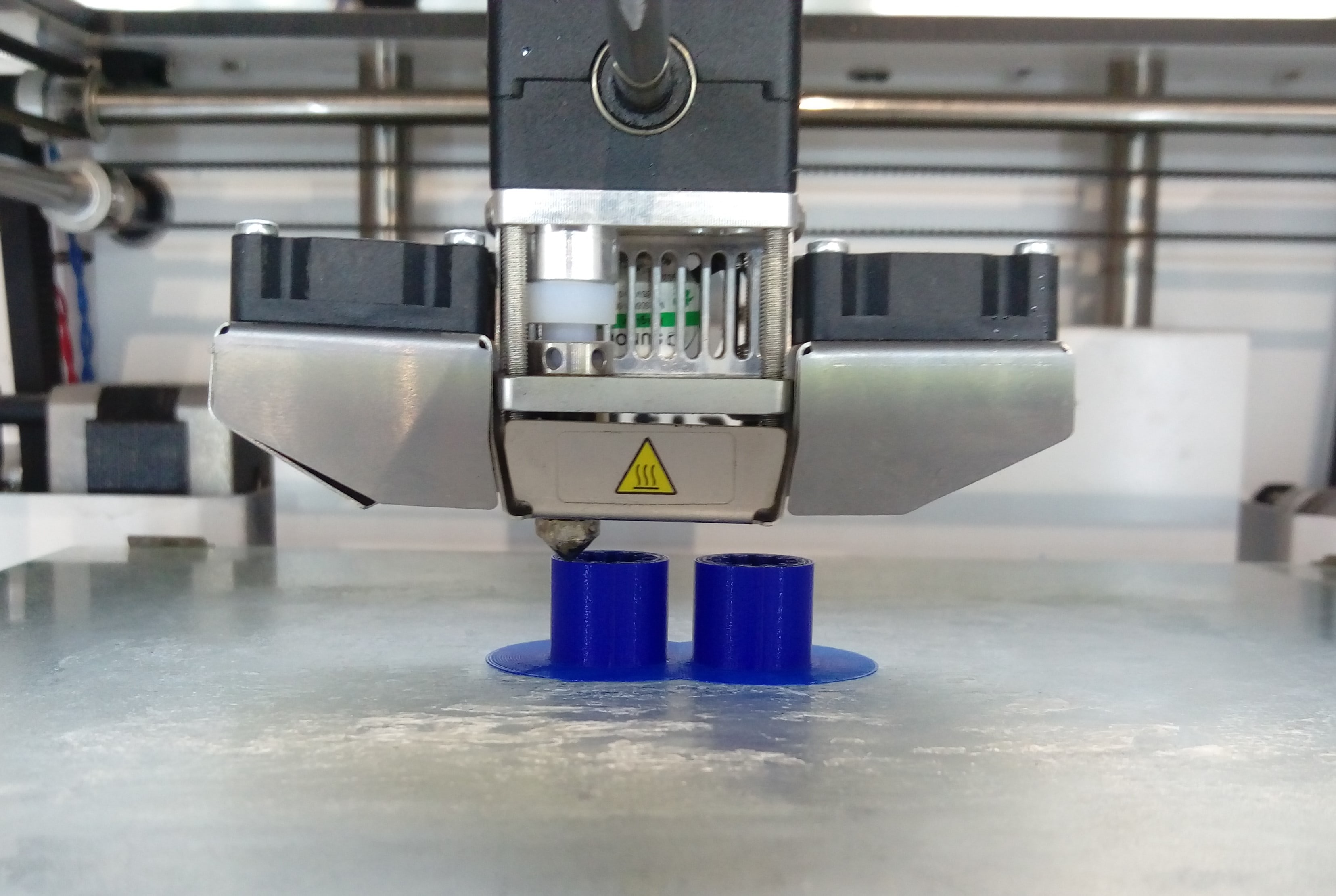
Another problem was we didn't have enough linear bearing, we had just one we used in extruder Z axis, but we need two more to use in X axis that moves the extruder so we printed them and added some lubricant to decrease friction in linear motion. I downloaded bearing designs from HERE.
Machine Automation
Week #15
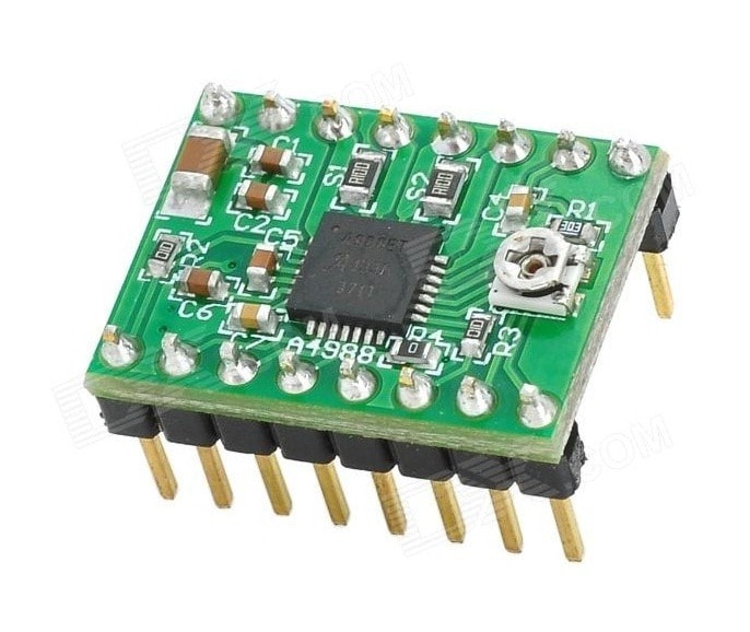
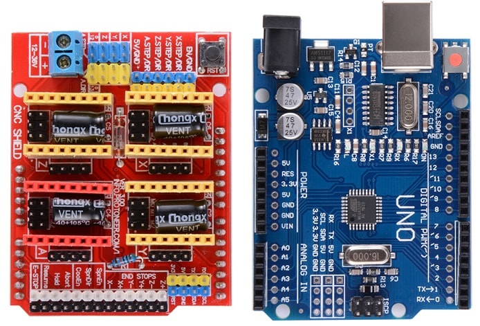
In this week we should move, control and automate our machine which we designed and assembled last week. To move stepper motors in our machine we used Pololu a4988 stepper motor drivers which will mount on CNC Arduino shield v3 Those components shown below:
We Followed This Tutorial to learn how to connect the CNC shield jumpers to select microsteps resolution for each motor, and how to add other motor in Y axis.
We used GRBL an open source CNC firmware, uploaded it to Arduino UNO and used < a href = https://github.com/winder/Universal-G-Code-Sender> Universal G-code sender interface software to send G-codes to the machine.
I start testing each axis separately by manually write and send single G-code line at a time. For example, to move just X axis I used G91 G00 X40 G91: To use incremental coordinate system which deal with the current position of the machine as a zero and move axes relative to this position.
G00: means rapid movement without feedrate.
X40: moves X axis 40 mm.
This video is an example of testing X axis:
Step Per Revolution Calculation
We have a Nema 17 stepper motor with 1.8 degree resolution, which means 200 step per revolution. To ncrease resolution we used 1∕16 microstep. Calculation of step per mm for each axis depends on the mechanism and components used on that axis, After determining the properties of the components I chose a suitable formula to find the final answer.
Y axis Calculation
In Y axis we used screw mechanism with 8mm pitch. To find step per mm I used this formula:
Step per mm = (Motor steps per revolution * Driver micro steps) ∕ screw pitch Step per mm = (200 * 16) ∕ 8 = 400 step∕mm.
Z axis Calculation
Also in Z axis, we used screw mechanism but with a pitch equal to 1.25mm. To find step per mm I used the previous formula:
Step per mm = (Motor steps per revolution * Driver micro steps) ∕ screw pitch Step per mm = (200 * 16) ∕ (Belt pitch *Pulley number of teeth)= 2560step∕mm.
X axis Calculation
In X axis we used pully and belt mechanism our pully has 25 teeth and the pitch of the belt is 2mm. To find step per mm I used this formula:
Step per mm = (Motor steps per revolution * Driver micro steps) ∕ (Belt pitch *Pulley number of teeth) Step per mm = (200 * 16) ∕ (2 *25) = 64 step∕mm
GRBL Modifiaction
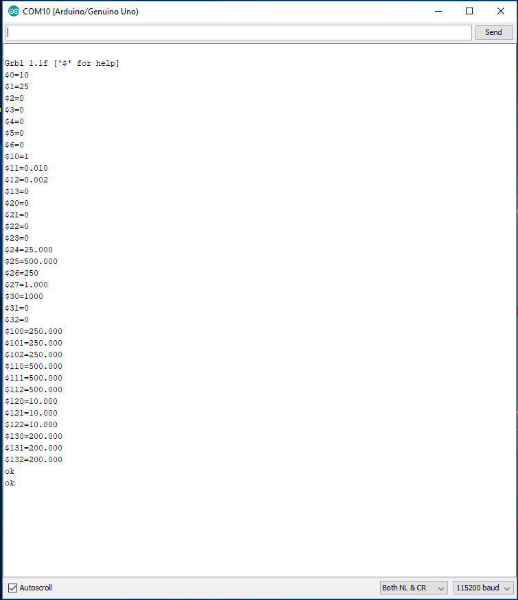
After I found step per mm for each axis I should modify these values in GRBL From This site I read how to change GRBL settings. First to know what is the current settings I opened the Serial monitor in Arduino IDE while it is connected to the shield and I worte $$ This was the result:
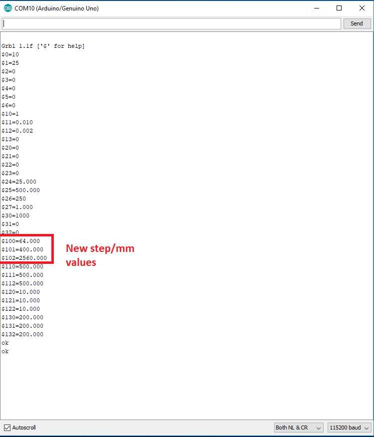
To change X, Y and Z step per mm values I should change $100,$101,$102 respectively to previously caculated values. This can simply done by writting for X axis $100=400 and the same for other axes. After that I wrote $$ to see the change in settings. This was the result:
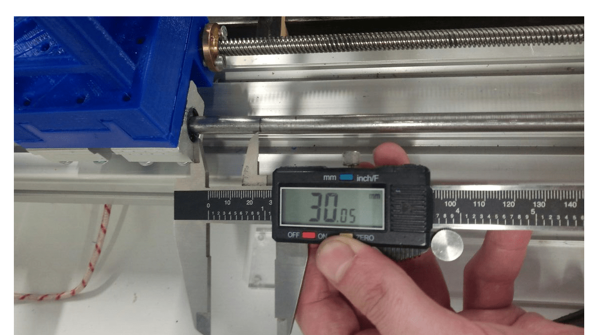
Now, after editing GRBL settings when I say to the machine move 40mm in an axis it should move exactly that distance. I successfully tested all axes. For example, to test Y axis I put a mark on the axis rod, then I wrote G91 G00 Y30 the result distance was measured using caliper:
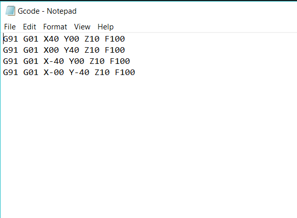
The last thing I did is writting a G-code to draw a squer with paste. This is my code:
Watch a video for the machine while drawing a squre:
Problems in Machine Automation
We faced a lot of problems in this week. The most critical one was the high load on the Y axis motor which leads to one motor moves and the other can not move. We solved this problem by increasing the power supply current limits.
Vibration in Z axis due to untight motor screws was another problem. you can watch it:
Opportunities of Improvements
Of course within two weeks we will not make a perfect machine or a final product machine, we did really a great job in that short time, but surely if we have more time we could make many improvements such as:
Design improvement ideas:
Improve the axes design to avoid problems we faced.
Replace 3D printed bearings and corners with actual metal components.
Redesign 3D printed Y axis parts to be made from more stable and robust material.
Find other plate and another way to fix it with frame.
Improve extruder design to be more efficient.
Develop the frame and the cover design for the machine to be more practical to use.
Improvement Ideas for Automation Part:
Do more tests to find optimum motors speeds.
Find the relation between motors movement and extrusion speeds.
Test machin%s behavior when drawing more complex shapes.
Connect heater's control with machine's control software.
Download my files
You can download all of my machine partes and assembly from
This Link