During this week we have learned about input devices which also called 'sensors'.The sensor is a device that convert a change in a physical quantity to a measurable change in electrical values i.e current , voltage , capacitance... Etc.
The main task is to program different sensors using our own boards
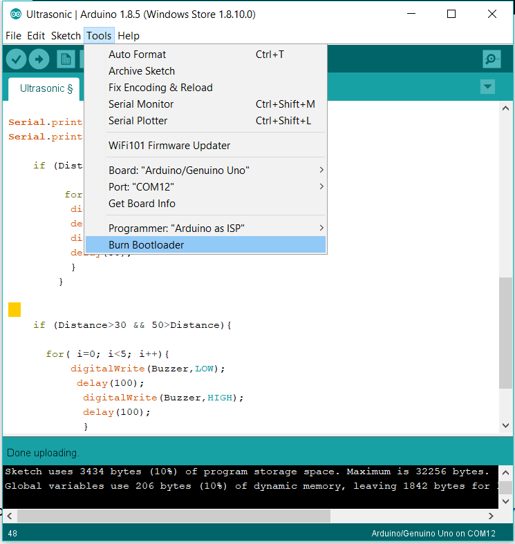
I used my General Purpose Board board with Atmega 328P microcontrolar chip, which I made in Electronic Design Week . I started by programming my Arduino using Arduino UNO as ISP following these steps:
Firstly, I will use an ultrasonic sensor because I will use it in my final project to let my robot avoid obstacles. Ultrasonic is a sensor sends ultrasonic waves at a specific frequency by TRGE pin, then ECHO pin receives the reflected wave. By programing a code you can measure the reflection time, then find the distance from the object by multiplying the time with the sound velocity 343m per secondand divide it by 2 ( because the wave go to the object and reflex from it). I found useful information and code examples
HERE
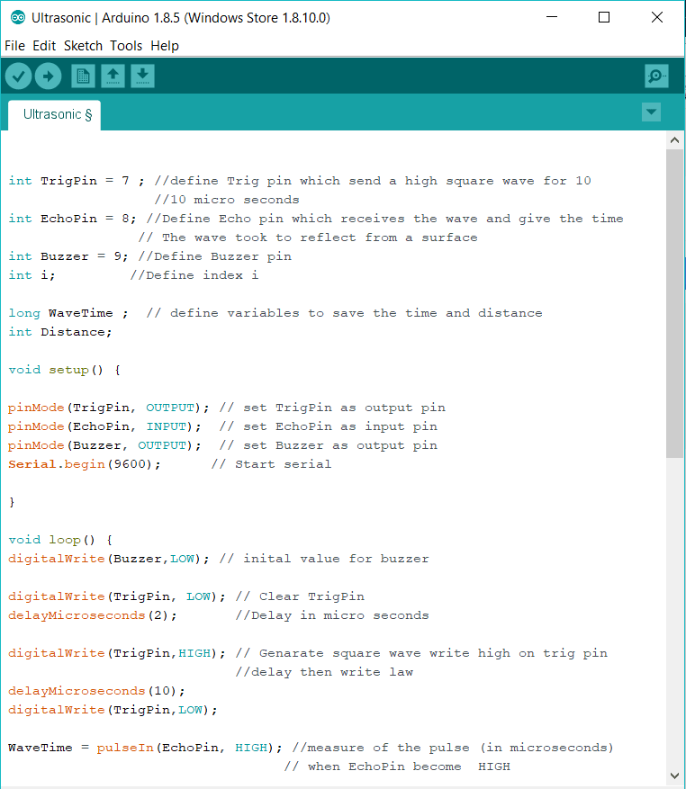
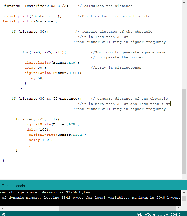
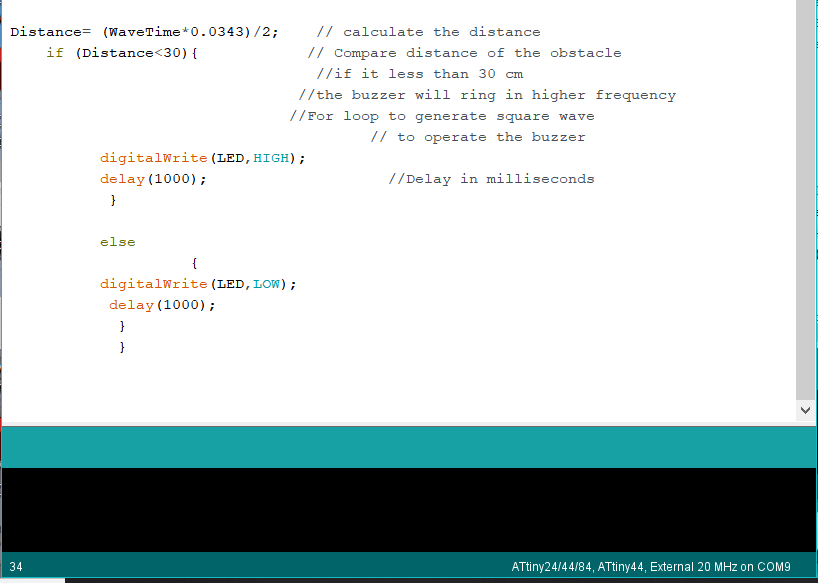
I wrote a code which measures the distance of an object and if it is between 50 and 30 cm the buzzer will emit sound with a frequency. and if it is less than 30 cm the buzzer will emit sound with a higher frequency. No sound if the distance is larger than 50cm.
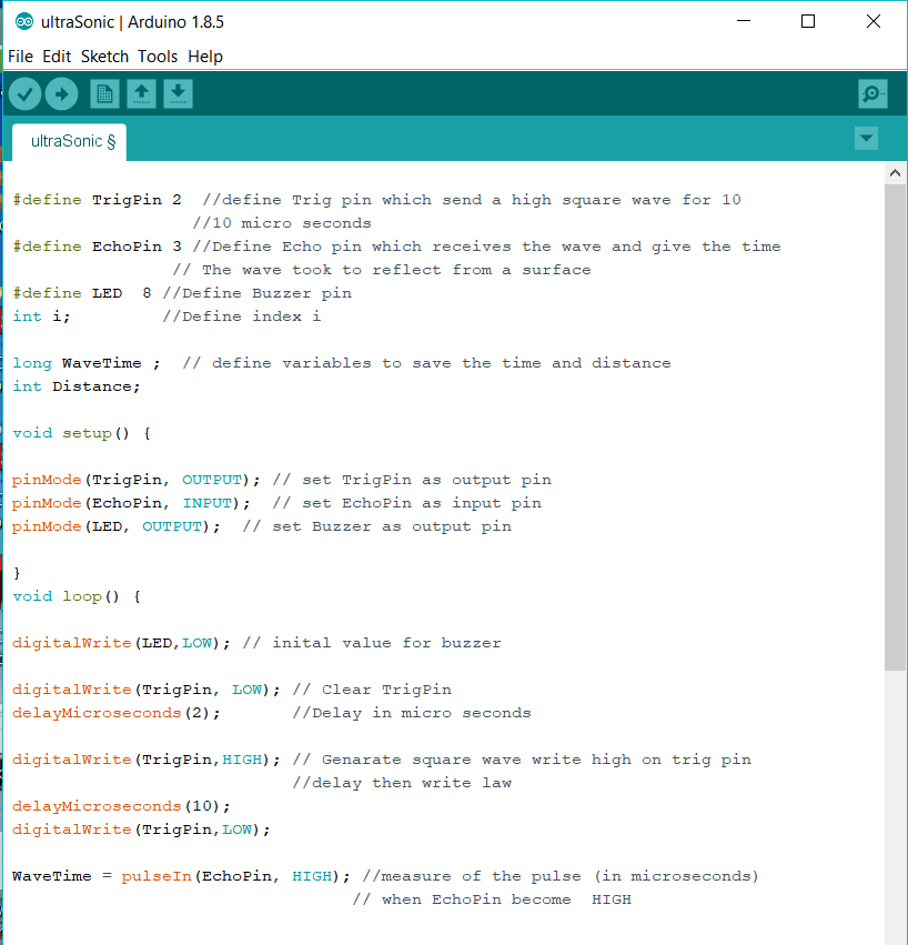
This is my code I explained each line within it by a command line.
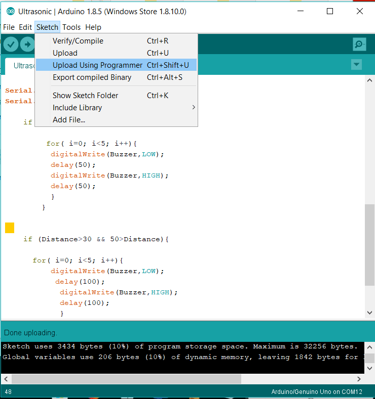
Then I connect My General Purpose Board with Arduino UNO and upload my code as shown in step 2 when I made burn bootloader. and upload as step 4 .
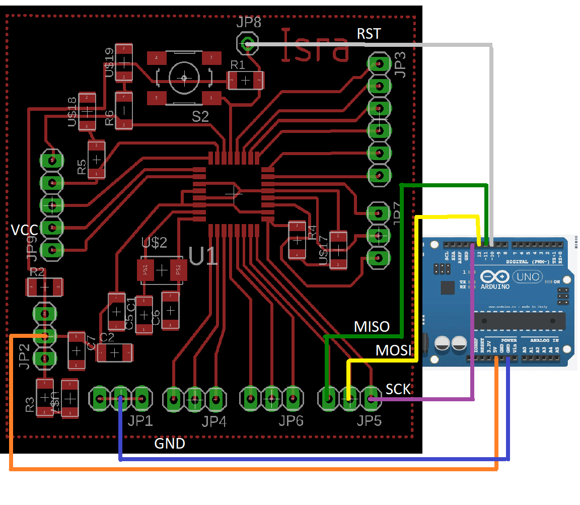
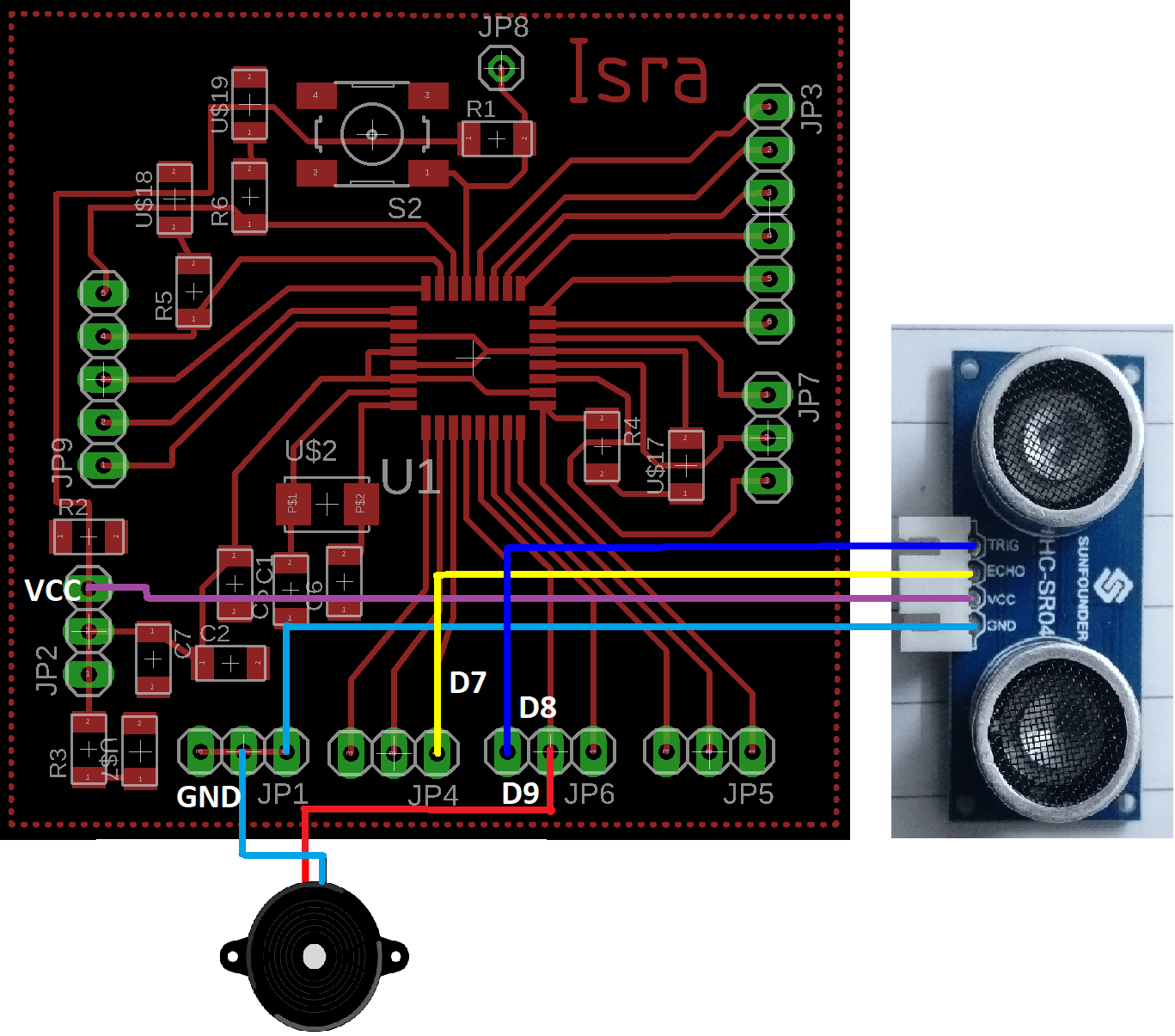
After uploading the code I disconnected all wires and connect the ultrasonic and buzzer with my General Purpose Board as shown:
Watch the video
Beside my General Purpose Board I want to design a specific input\output board for ultrasonic sensor and servo motor. I repeated steps of Electronics Design Week to design, produce and program my new board. I will briefly mention important steps for detailed documentation, please back to electronics design week.
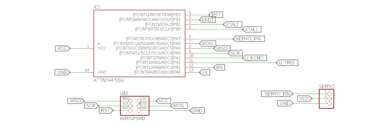
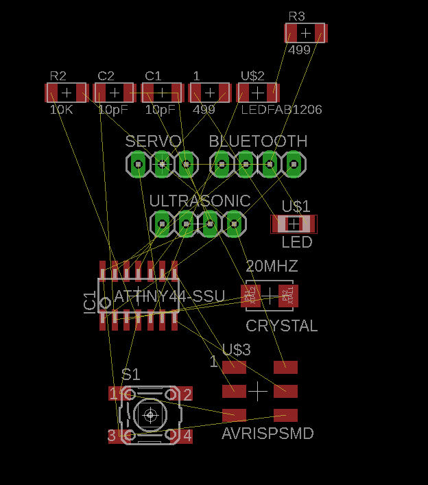
I ![]() EAGLE software to design my board. In schematic I used these components: Attiny44 microcontroller chip, AVR ISP pin header, 20MHZ
EAGLE software to design my board. In schematic I used these components: Attiny44 microcontroller chip, AVR ISP pin header, 20MHZ
This is my schematic:
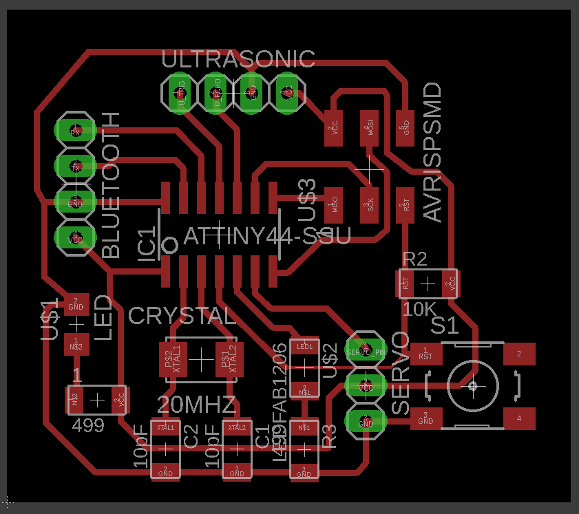
My booard layout before start roughting :
My booard layout after roughting:
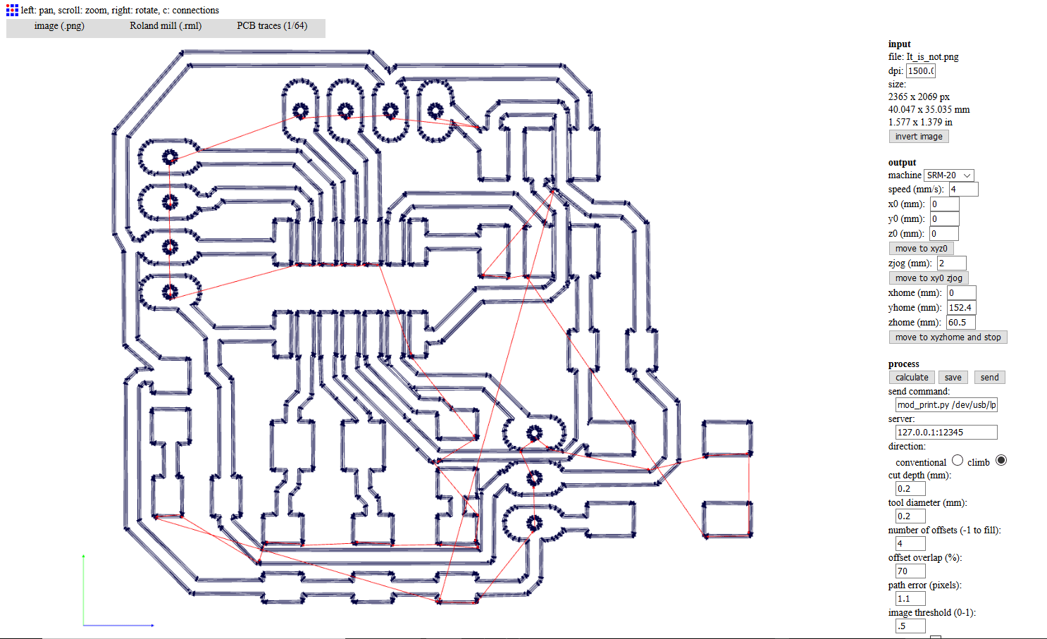
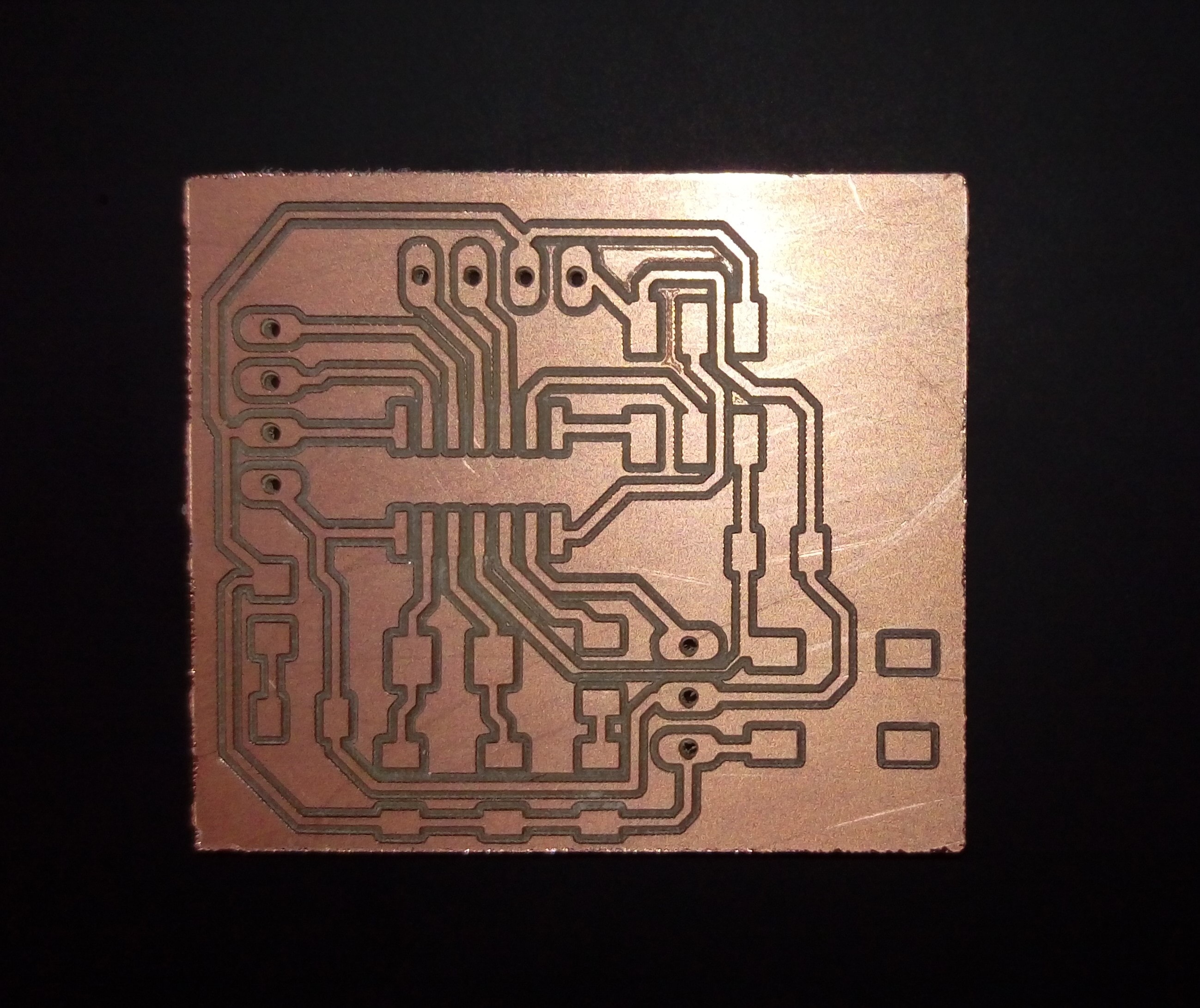
To fabricate my board I prepared three jobs. The first one is for inside traces seen in this PNG picture:

Fab Modules settings to generate G-code:
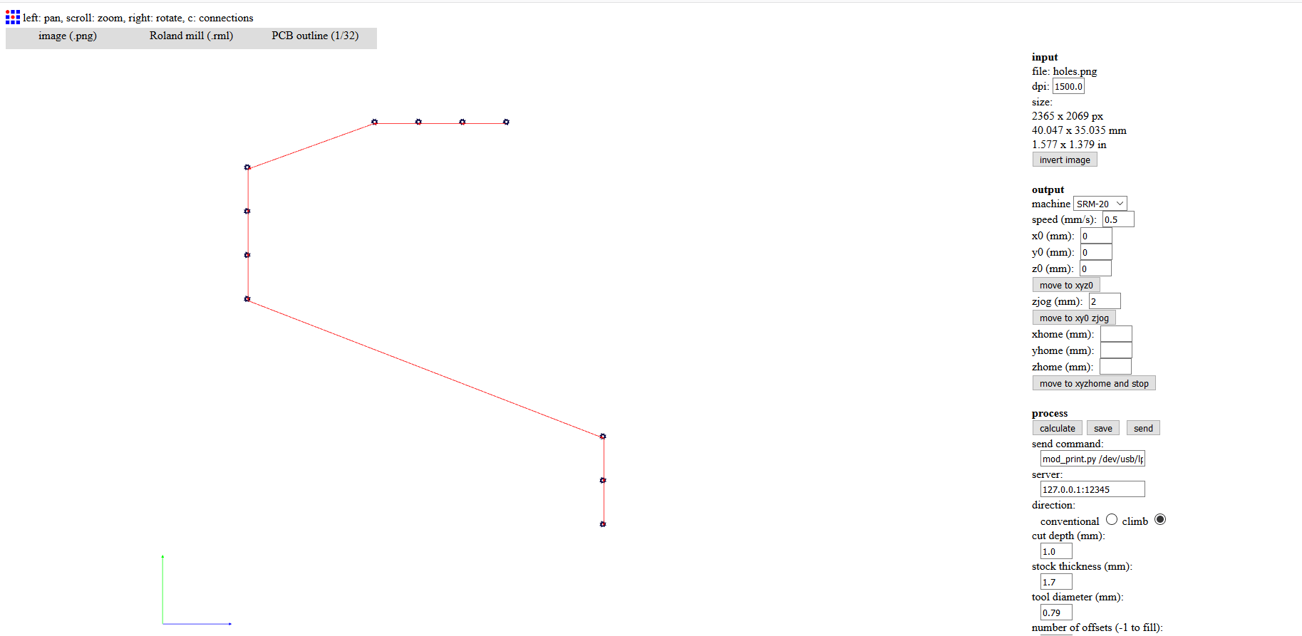
Second job is for holes drilling:

Fab Modules settings :
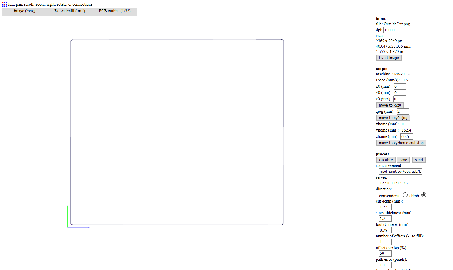
The last job is for out cut:

Fab Modules settings :
My board after milling:
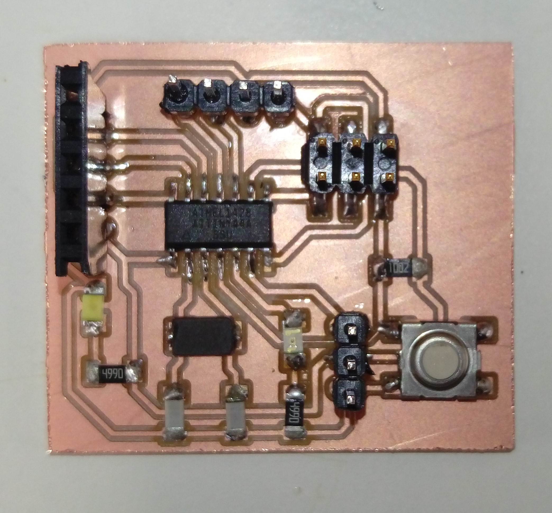
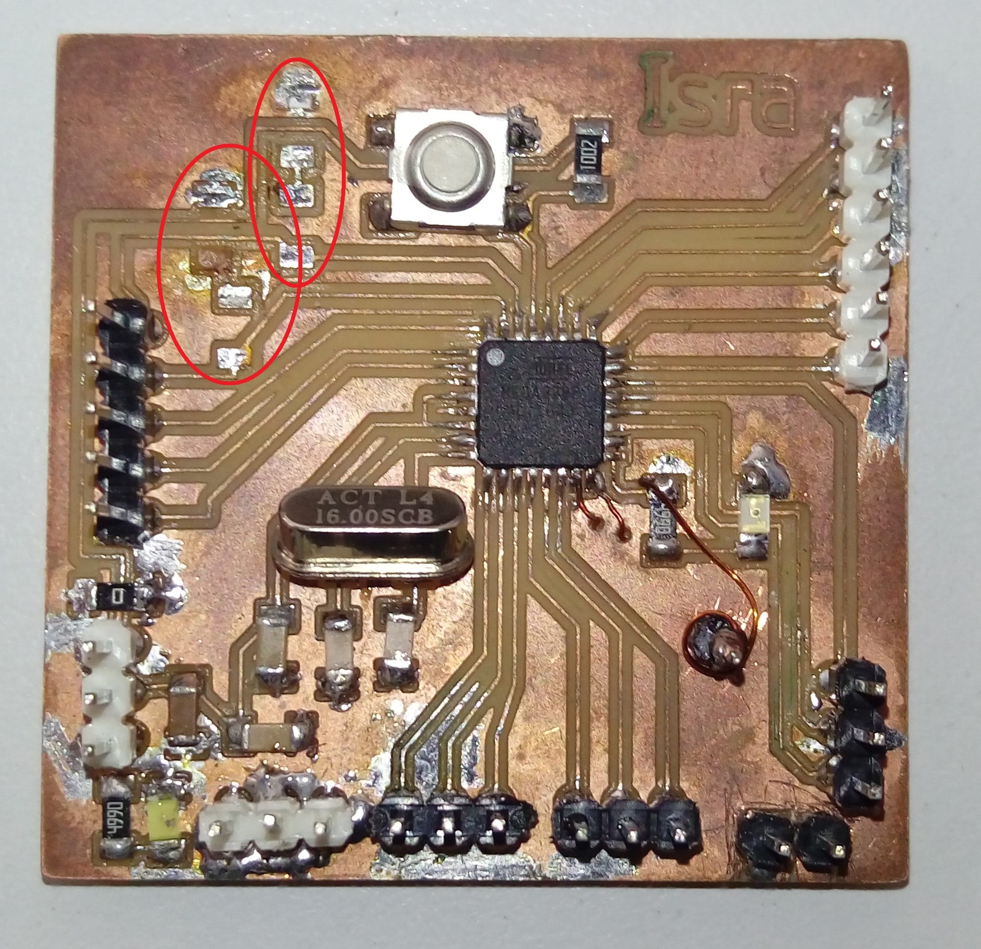
After soldring it looks like:
Programming time!. Firstly, to burn bootloader I just do exactly what I did when MY Hello Echo ATtiny44 board using Arduino UNO as ISP, because both have the same MCU and AVR ISP connection. I will not repeat that procedure because it well documented in Step#9 in Electronics Design Week.
At this step, I modified the previous code I used with ultrasonic sensor and my General Purpose Board to match the pin connection of ATtiny board, also I replaced the buzzer with the buid-in LED connected to pin 8 which will light if the sensor detect any object in distance less than 30cm . This is the modified code :
Watch the video
To download my codes for ultrasonic and my board schematic and layout:
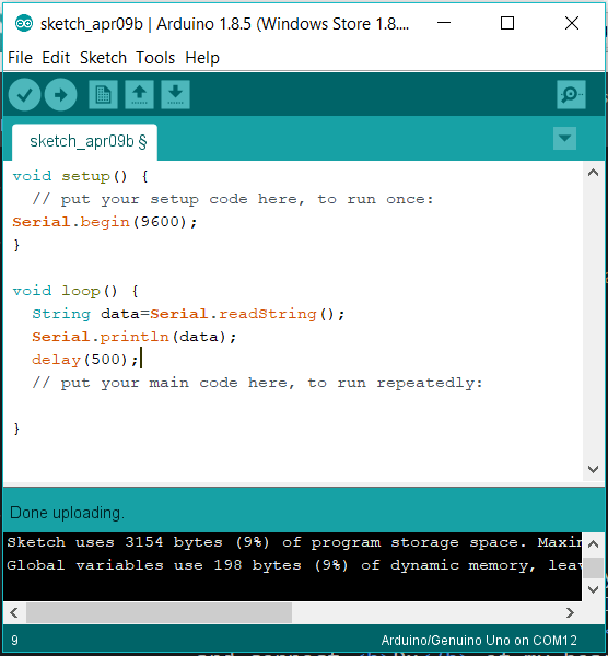
I want to read the distance from my Arduino usingSerial.Read((and Serial.Println(( What I did after upload the code to my Arduino I upload this code to Arduino UNO
Then connect Rx of my board to Tx of UNO and Tx of mine to Rx of UNO but nothing works I got some readings then stopped : '( . I think there is a problem in my board connections in the reagon for RX and TX because I connect some LEDs theres. I desolder every thing as shown, but I nothing works
A piezoelectric sensor is a simple sensor based on a piezoelectric effect in some special materials which is the change of material's charge due to apply force on it, by this phenomenon we could measure force, pressure, strain and many other physical quantities.
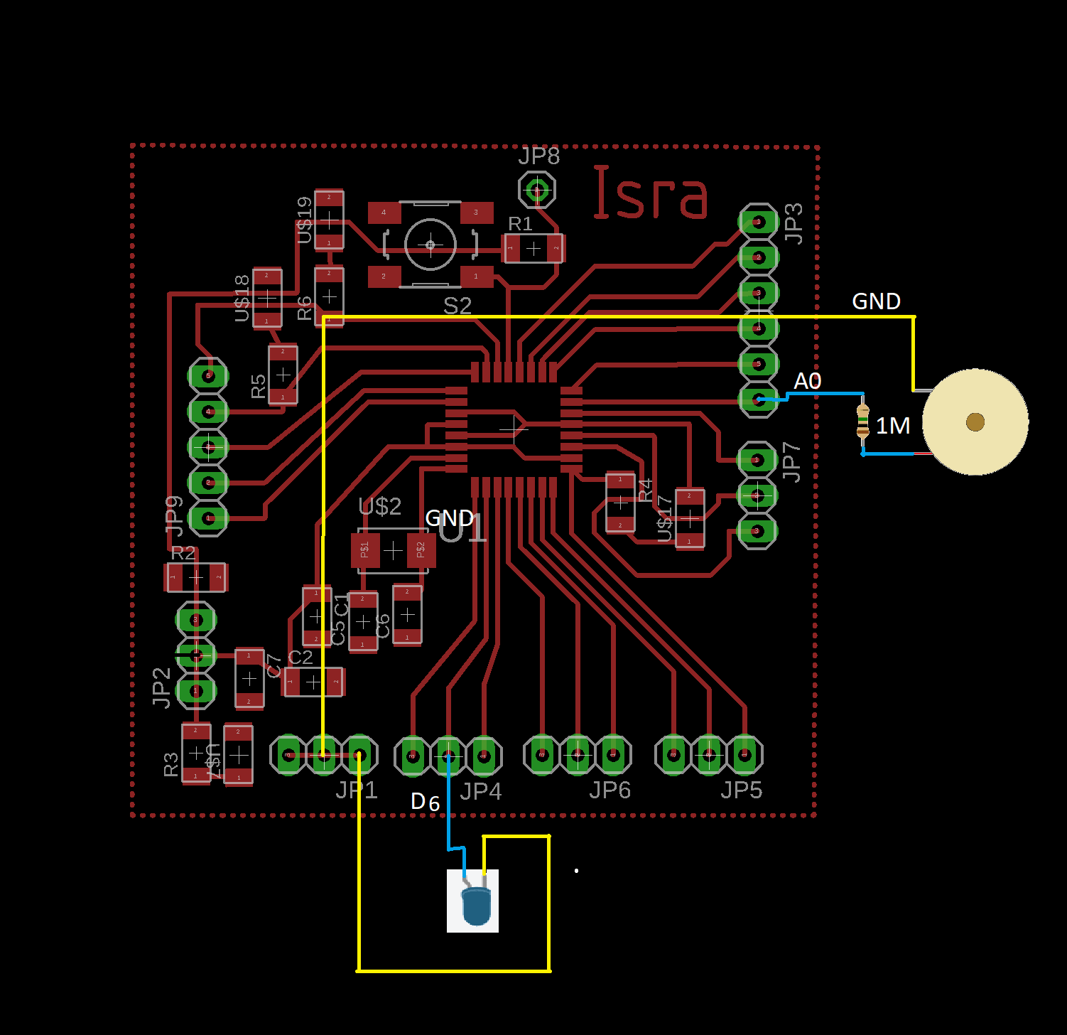
I connected the piezoelectric sensor with my designed board, also added an LED to the PWM pin to change its brightness due to force and vibration applying by my finger. This is the connection:
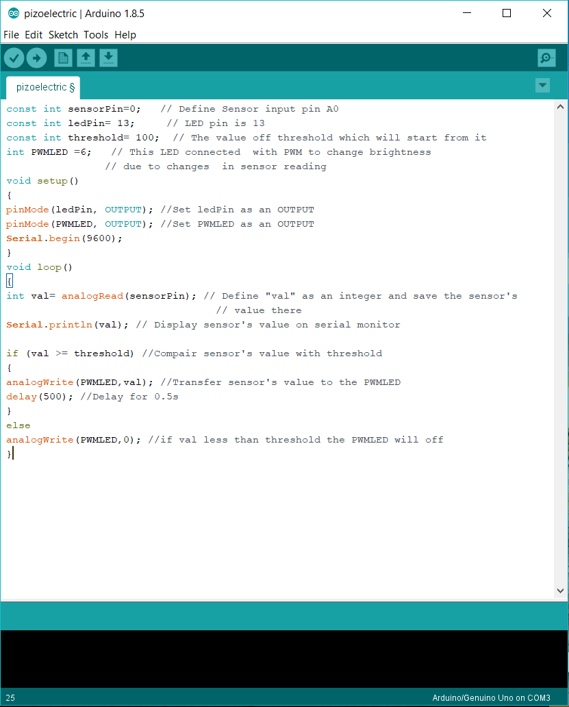
This is my Arduino code with comments explaining each line function. Then I uploaded this code to my board as I previously did with the ultrasonic sensor.
Watch the video
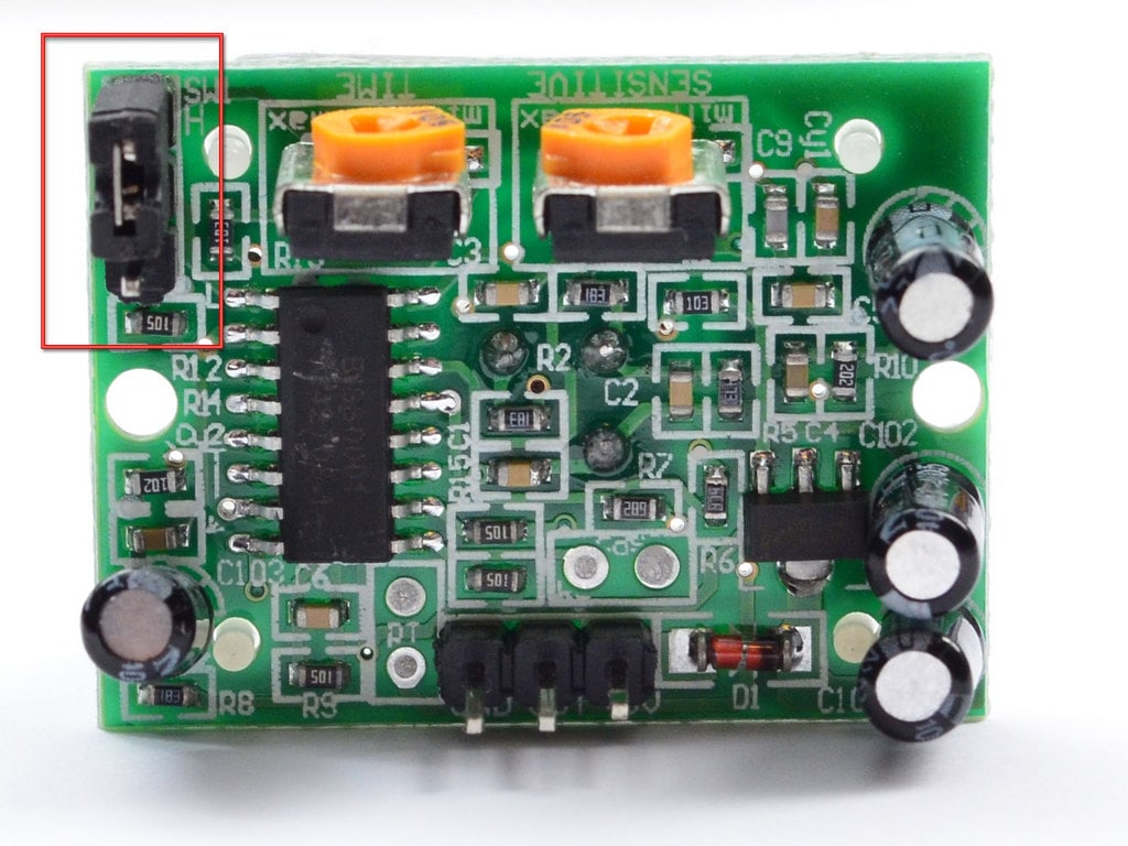
The PIR sensor module made of pyroelectric sensor, which can detect some levels of infrared radiation. Everything around us emits low levels of IR which is directly proportional with the temperature of the bodies. PIR sensor measures the change of IR not the levels of it, to do that the sensor split into two halves to cancel each other if they are equal. The pyroelectric sensor covered with plastic cover which consists of many regions, each region is a Fresnel lens which will increase the detection area of the sensor. visit this page for a detailed explanation of how PIR sensor works.
The PIR sensor has 3 pins GND and VCC at the edges and OUT in the middle this pin will send a high voltage when detect a motion. Also, there are two potentiometers, one is for controlling the sensitivity of the sensor and the other is for controlling the time of setting pin OUT as HIGH after detection any movement. There are two operating modes for PIR depending on the position of the jumper. The first mode is Non-retriggering mode in this mode the pin OUT will change from HIGH to LOW after adjusted time is over regardless the motion is still detecting or not. Retriggering mode keeps pin OUT HIGH whenever there is a motion if there is no motion it will turn to LOW after adjusted time is over. The picture below shows PIR sensor in Retriggering mode.
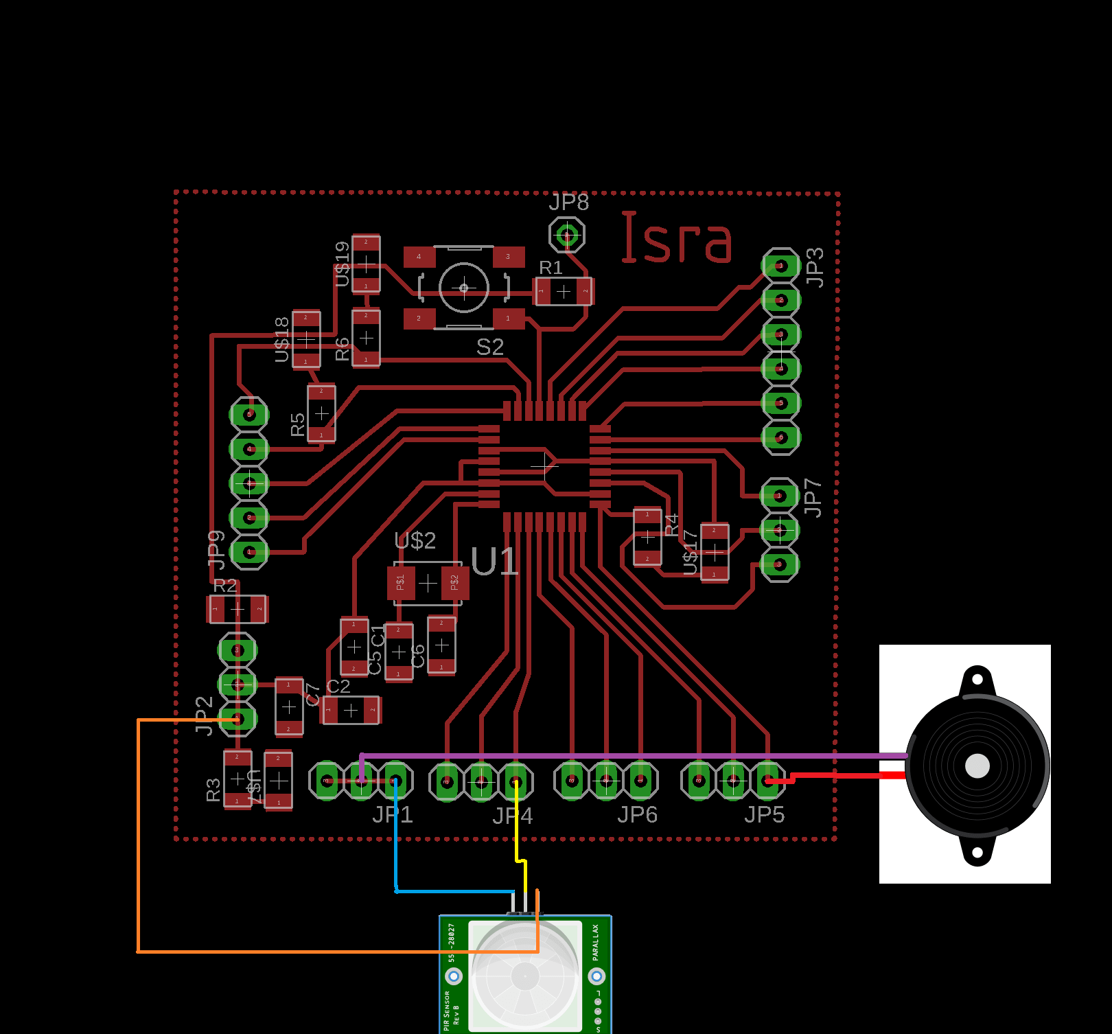
This is the connection of PIR sensor with my Arduino board. I used Retriggering mode.
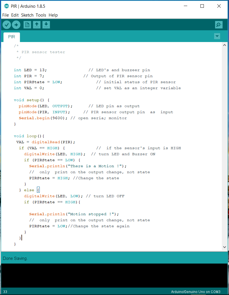
In my code I connected a Buzzer with the LED to give me a sound beside the light when a motion is detected. The explanation of my code is commented beside each line as shown:
Watch the video
Download my codes for each sensor