This is the thirteenth week assignment for the Fab Academy 2018.
.Networking and communications

The above messy connection shows how I connected my board to the arduino, the code I'm writing is to communicate a command from the arduino to my board through software serial communication.
Using the serial monitor, I send a command to the arduino and which in return sends it to the atmega board and depending on the received data, the atmega lights an LED or turns it off.
As you can watch in the video
#include  <SoftwareSerial.h>
#define led 7

SoftwareSerial mySerial(1,0); // RX, TX
char incoming;
void setup() {
  // Open serial communications and wait for port to open:
 mySerial.begin(9600);
 pinMode(led, OUTPUT);
}
void loop(){
 if(mySerial.available()){
  incoming=mySerial.read();
  if (incoming=='1'){
    digitalWrite(led, HIGH);
  }
  else if(incoming == '0'){
  digitalWrite(led,LOW);
  }
  }
  delay(1000);

      delay(1000);

 }
Here is the my atmega code
#include <SoftwareSerial.h>
SoftwareSerial ser (10,9); // rx, RX ;
String data;
void setup() {
  // put your setup code here, to run once:
  Serial.begin(9600);
 // ser.begin(9600);

}

void loop() {
  // put your main code here, to run repeatedly:
  if(Serial.available()){
    data=Serial.readStringUntil('\n');
    Serial.println(data);
    ser.println(data);
    Serial.println("command sent");

  }

}
Downloads
atmega_codearduino_code
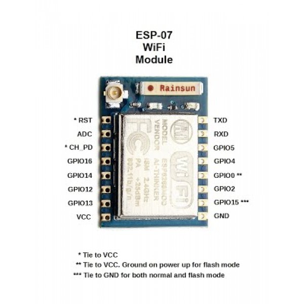
WiFi module ESP8266mod
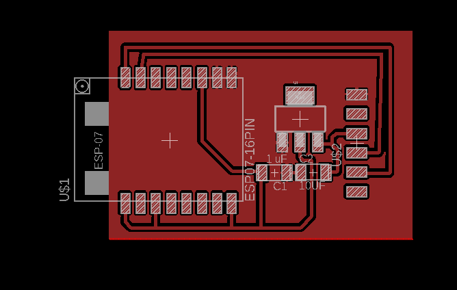

I am using the fixed voltage regulator that outputs 3.3V. At first I used a 5V FTDI cable but one of my colleague’s board burnt and we thought it’s due to that so we all switched to a 3.3V ftdi cable
this the components:
1. ESP8266mod
2. The LM1117 which is a series of low dropout voltage regulators with a dropout of 1.2V at 800mA of load current. It has the same pin-out as National Semiconductor's industry standard LM317. The LM1117 is available in an adjustable version, which can set the output voltage from 1.25V to 13.8V with only two external resistors.
3. One capacitor 1mf
4. One capacitor 10mf
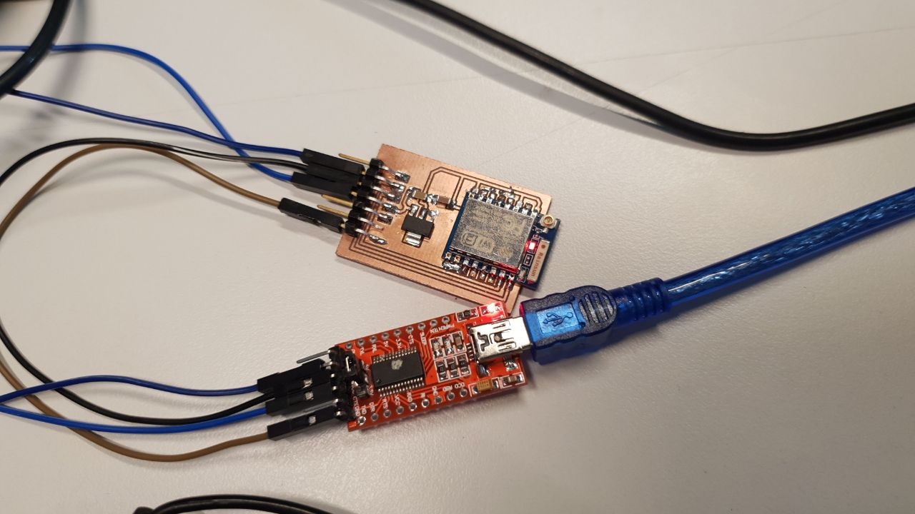
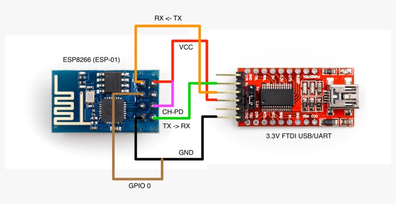
I used the ftdi USB to TTL because the ESP should working in 3.3 volt and the pc has 5 volt .
I used this tutorial to help me with that.
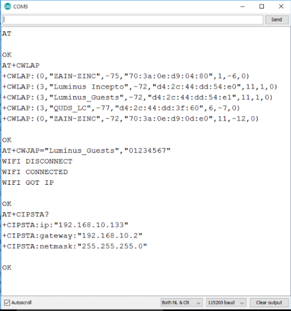
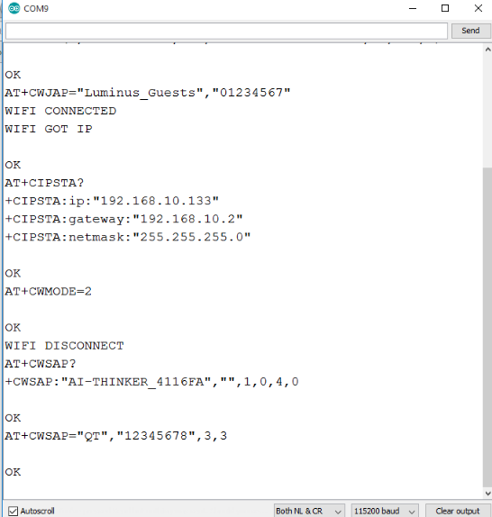
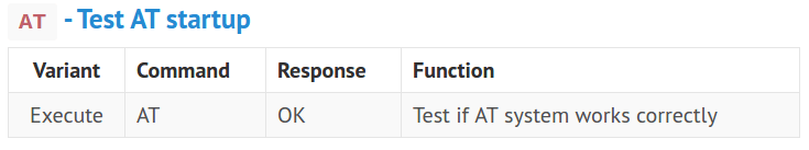
AT: is used to see if the wifi module is working fine and responding. The correct response from the wifi should be "ok"
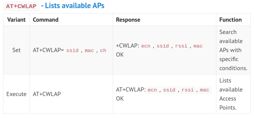
AT+CWLAP: is used to list all available access points to connect to.
AT+CWJAP="ssid","password": is used to connect to a network.
AT+CIPSTA?: is used to get the IP Address of the chip.
AT+CWMODE=2: is used to switch to host mode. Host mode means that other devices can connect to the wifi chip meaning it is an access point now. Other modes are: 1 is client, 3 is dual.
AT+CWSAP?: is used to check the name of the network.
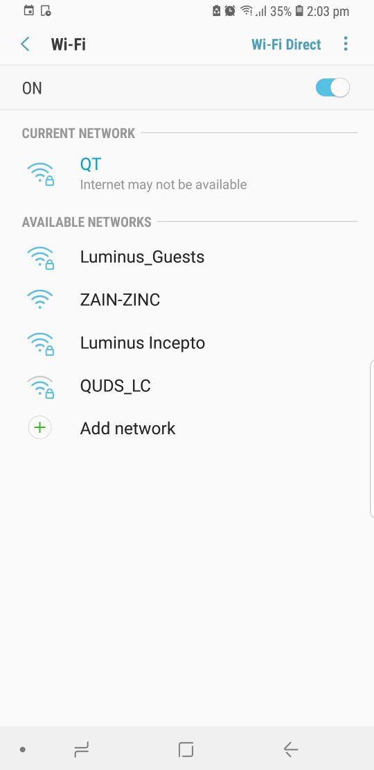
AT+CWASP="QT","12345678",3,2 : is used to change the name of the network, the password, the channel and the encryption method used.
I used the above mentioned AT commands to configure my wifi module.
Then I used AT+CWSAP? to check the name of the network.
The above screenshots are from my mobile phone to connect to the network I created with the wifi module.
AT


OK
AT+CWLAP

+CWLAP:(0,"ZAIN-ZINC",-75,"70:3a:0e:d9:04:80",1,-6,0)
+CWLAP:(3,"QUDS_LC",-78,"d4:2c:44:dd:3f:60",6,-7,0)
+CWLAP:(3,"Luminus Incepto",-70,"d4:2c:44:dd:54:e0",11,1,0)
+CWLAP:(3,"Luminus_Guests",-71,"d4:2c:44:dd:54:e1",11,1,0)
+CWLAP:(0,"ZAIN-ZINC",-75,"70:3a:0e:d9:0d:e0",11,-12,0)

OK
AT+CWJAP="Luminus_Guests","01234567"

WIFI CONNECTED
WIFI GOT IP

OK
AT+CIPSTA?

+CIPSTA:ip:"192.168.10.133"
+CIPSTA:gateway:"192.168.10.2"
+CIPSTA:netmask:"255.255.255.0"

OK
AT+CWMODE=2


OK
WIFI DISCONNECT
AT+CWSAP?

+CWSAP:"AI-THINKER_4116FA","",1,0,4,0

OK
AT+CWSAP="QT","12345678",3,3


OK
I used a ESP8266 to control an LED and a buzzer through a webpage. I followed this tutorial to guide me into making a webserver.
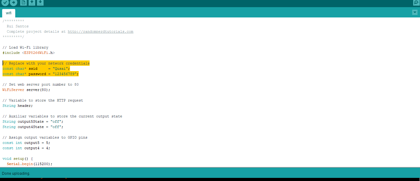
As seen in the above photo, I changed the SSID of the
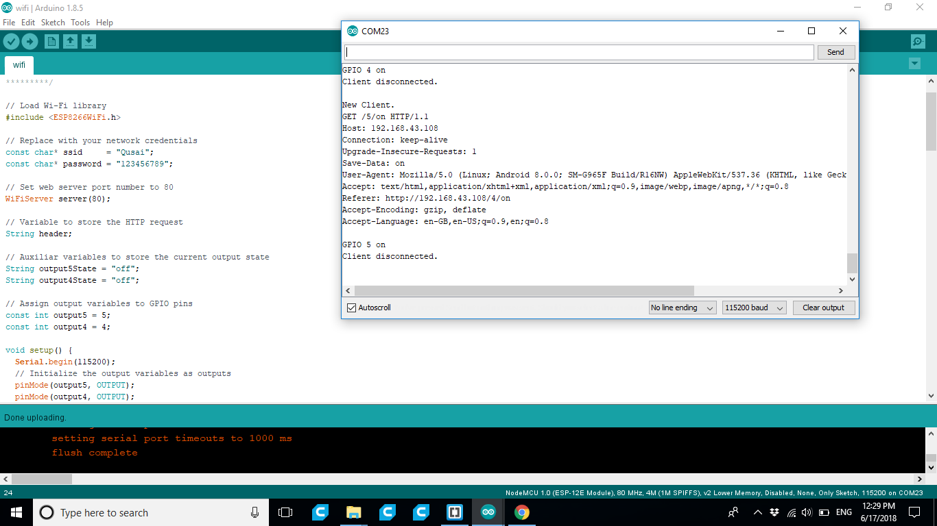
If take a look at the serial monitor, you can see what's going on on the background. The ESP receives an HTTP request from a new client – in this case, your browser.
You can also see other information about the HTTP request – these fields are called HTTP header fields, and they define the operating parameters of an HTTP transaction.
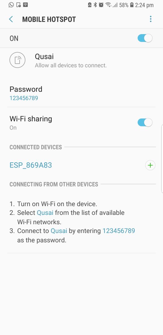
connected to my phone hotspot
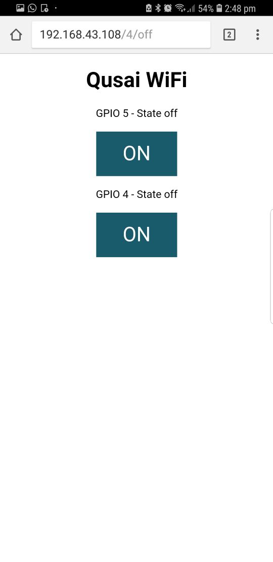
This page is sent by the ESP8266 when you make a request on the ESP IP address.
watch the video demonstration
/*********
Rui Santos
Complete project details at http://randomnerdtutorials.com
*********/
// Load Wi-Fi library
#include
// Replace with your network credentials
const char* ssid = "Qusai";
const char* password = "123456789";
// Set web server port number to 80
WiFiServer server(80);
// Variable to store the HTTP request
String header;
// Auxiliar variables to store the current output state
String output5State = "off";
String output4State = "off";
// Assign output variables to GPIO pins
const int output5 = 5;
const int output4 = 4;
void setup() {
Serial.begin(115200);
// Initialize the output variables as outputs
pinMode(output5, OUTPUT);
pinMode(output4, OUTPUT);
// Set outputs to LOW
digitalWrite(output5, LOW);
digitalWrite(output4, LOW);
// Connect to Wi-Fi network with SSID and password
Serial.print("Connecting to ");
Serial.println(ssid);
WiFi.begin(ssid, password);
while (WiFi.status() != WL_CONNECTED) {
delay(500);
Serial.print(".");
}
// Print local IP address and start web server
Serial.println("");
Serial.println("WiFi connected.");
Serial.println("IP address: ");
Serial.println(WiFi.localIP());
server.begin();
}
void loop(){
WiFiClient client = server.available(); // Listen for incoming clients
if (client) { // If a new client connects,
Serial.println("New Client."); // print a message out in the serial port
String currentLine = ""; // make a String to hold incoming data from the client
while (client.connected()) { // loop while the client's connected
if (client.available()) { // if there's bytes to read from the client,
char c = client.read(); // read a byte, then
Serial.write(c); // print it out the serial monitor
header += c;
if (c == '\n') { // if the byte is a newline character
// if the current line is blank, you got two newline characters in a row.
// that's the end of the client HTTP request, so send a response:
if (currentLine.length() == 0) {
// HTTP headers always start with a response code (e.g. HTTP/1.1 200 OK)
// and a content-type so the client knows what's coming, then a blank line:
client.println("HTTP/1.1 200 OK");
client.println("Content-type:text/html");
client.println("Connection: close");
client.println();
// turns the GPIOs on and off
if (header.indexOf("GET /5/on") >= 0) {
Serial.println("GPIO 5 on");
output5State = "on";
digitalWrite(output5, HIGH);
} else if (header.indexOf("GET /5/off") >= 0) {
Serial.println("GPIO 5 off");
output5State = "off";
digitalWrite(output5, LOW);
} else if (header.indexOf("GET /4/on") >= 0) {
Serial.println("GPIO 4 on");
output4State = "on";
digitalWrite(output4, HIGH);
} else if (header.indexOf("GET /4/off") >= 0) {
Serial.println("GPIO 4 off");
output4State = "off";
digitalWrite(output4, LOW);
}
// Display the HTML web page
client.println("");
client.println("");
client.println("");
// CSS to style the on/off buttons
// Feel free to change the background-color and font-size attributes to fit your preferences
client.println("");
// Web Page Heading
client.println("Qusai WiFi
");
// Display current state, and ON/OFF buttons for GPIO 5
client.println("GPIO 5 - State " + output5State + "
");
// If the output5State is off, it displays the ON button
if (output5State=="off") {
client.println("");
} else {
client.println("");
}
// Display current state, and ON/OFF buttons for GPIO 4
client.println("GPIO 4 - State " + output4State + "
");
// If the output4State is off, it displays the ON button
if (output4State=="off") {
client.println("");
} else {
client.println("");
}
client.println("");
// The HTTP response ends with another blank line
client.println();
// Break out of the while loop
break;
} else { // if you got a newline, then clear currentLine
currentLine = "";
}
} else if (c != '\r') { // if you got anything else but a carriage return character,
currentLine += c; // add it to the end of the currentLine
}
}
}
// Clear the header variable
header = "";
// Close the connection
client.stop();
Serial.println("Client disconnected.");
Serial.println("");
}
}
Problems
I wasted a fair amount of time, trying to send AT commands to my WiFi Module and it was not responding. After tracing back my steps I discovered that I miss connected the FTDI to the Wifi as I connected the Rx to the Rx and the Tx to the Tx instead of switching them.
After that, everything worked fine.
Download
WIFI BoardsWIFI Boards
