This is a third week assignment for the Fab Academy 2018..
1. we had to create something using the vinyl cutter.
2. test the kerf of a material
3.using the laser cutter and create somthing with joints
I started with the vinyl cutter while I didn't have a clear idea what to do; then I have decided to make a logo for my project. In designing the logo I took the first sketch I have drawn for my final project and made the below steps.


I used Corel photo paint 2017; first I have downloaded it as a trial; download can be made by pressing the above icon. I opened new page and dropped the sketch.

I have chosen grayscale; when you click it it gives options.

These are the options you get; you can shift the bars left or right to choose the best percentage you desire.

Then went to Line Art you can notice the difference between the original sketch and picture shown above.


I clicked on Crop tool to crop the picture and I have saved it as PDF file; also you can export to PDF or any extension you desire.
Then I went using software called Coreldraw; this can be loaded all together as one package

I pressed open and imported the saved file.

I pressed the text icon to add a text to the picture

The text I have added is the name of the final project and called it Fab Extruder.

I pressed Artistic Media tool as I have add a drawing for the filament

I went to colors to choose the desired colors; I made sure not to choose the red color as the vinyl cutter reads the red color as a cutting order

I went to Contour tool and made a contour around the picture

I went back to colors and put the color for the contour red RGB to be cut order

I made hidden for the image only to check how it will look.

It is important to choose the width to be hairline

It is ready for print and cut.
versaworks
Versaworks; it is a software for the machine we have in the Lab which Roland sg300 which is very powerful machine.


I placed the vinyl roll into the machine; as you can see on the left side but also there is another one on the right side it is important that the beginning of the roll to be from the arrow so the machine can read the width.

There are many options as shown the bar on the left side and you can change the scale to the desired scale.

As shown I scaled it down and reduced the head speed to 800 to be more accurate.

The machine give option of print or print & cut or cut only; I clicked the cut only to check that cut process will be right.

is ready to print & cut and to do so click right on the saved file and the process will start

Before printing vinyl I tested it on a paper roll.

You can choose sheet cut from the function key on the machine and it will start cutting the sheet.

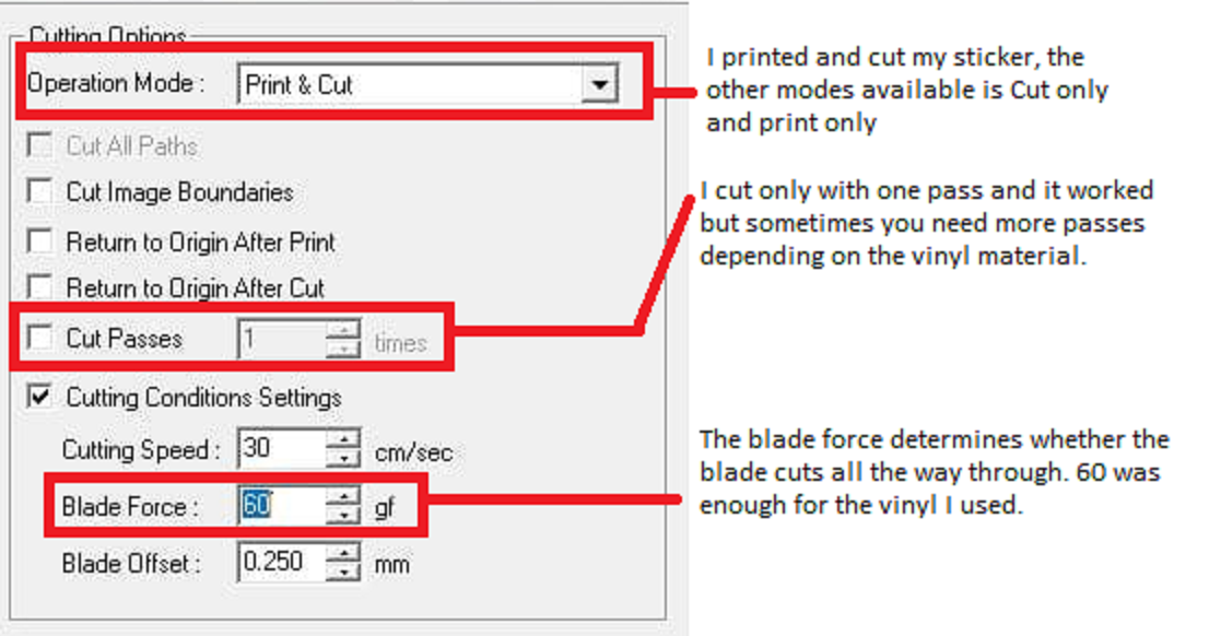
The above image shows the explanation of the cut settings I used.
When I used the vinyl roll I changed blade face to 50 gf as to as the thickness of the vinyl is more than the thickness of paper.

You can see the final log on paper and vinyl which will be placed on the final project
Download The Design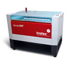
The above is a picture of the laser cutter that we have in our Lab it is trotec Speedy 400. It is an accurate, powerful and speedy machine. For safety reasons you need to make sure that ventilation is on and working well also it is recommend not to cut on it any materials that you don't have clear information about it and its origin; moreover any shiny materials that give reflections not to be cut on it. It is highly recommended to have next to you an extinguisher; for further information you can click on the photo which will direct you to its website.
Kerf Test


The Equation
Kerf = (Designed length - Actual length )/numbers of cuts
I had to make a Kerf test for Acrylic materials and their thicknesses of 6mm . I have drawn a rectangle to check the best kerf in different settings; at the beginning i made two lines which lead to double cutting so i found a mistake and changed to one line. First tested on 6 mm Acrylic the best result reached is the difference on the caliper is 0.47 mm; for further information and details this link will direct you to Group assignment.

I have these joint on Acrylic 6 mm and the joint is 5.8 mm to check how it will fit on my design as this material will be used in making my design
Acrylic Settings

This simple table is the best settings we found Acrylic.
laser cutter and create something with joints
I have decided to design and make a side lamp connected by joints only not using glue or nails. I have used Fusion 360 software as parametric software

First I have made a 2D sketch with the dimensions of 420*450 mm.

I have made a joint of opening of 6 mm

I mirrored it to the other side.

This is like a video which you can playback and edit the features on the sketch. I have increased the bottom length to 5.8 mm and made an opening so now we have two parts one with opening and taller while the other shorter and without opening.

Here I have changed the joint opening to 3 mm and by default the other side change also.

I saved the file as DXF file. As a beginner on Fusion 360 I couldn't save the file on this software as DXF so I exported it to Solidwork and there I saved as DXF file to ensure that the data is saved and will not be lost. Having done that I went back to Fusion 360 and learnt how to save DXF files as shown above.

I exported the DXF file to Inkscape which is a 2D software model. I have lined the RGB in red as the laser cutter programmed to read red as cut also lined the hairline. I have made a print.

It took me to the job controller of the machine and I have entered the settings which were determined earlier to be the best settings.

After cutting.

I found that there was a dimension variation on the base holder of 2 mm which prevented to have as flat base while joints

I have adjusted the difference manually and it fit perfectly.
After finalizing the base I’ll start with the top of the lamp; I have decided to use cardboard for the top and will start with a pattern.

I started with making rectangle on AutoCAD also I drew hinges to connect parts together as the shape with be round.

I have copied the hinges and added them to the other side with same dimensions to connect together at Kurf we have done in the Group assignment.

I have chosen the option measure to make sure that the dimensions are correct then I have save it as DXF file.


I have made the assembly as shown in the photo and the Kurf fit perfectly.
Download The Design Download The Design Download The DesignUpdated lamp
Due to the geometrical aspect of the lamp, it was easier to change base’s thickness to 5 mm. The previous lamp I made was of 6 mm thick, taking KERF into consideration, as shown in the below link for the group project.
For MDF of thickness 5mm, the kerf was measured to be 0.053mm.


I used the same pattern as previous lamp using cardboard as well. The cardboard was cut into 4 pieces to shape a square when assembled

Above are the settings used for cutting the cardboard


Final lamp assembled.
Download The Design Download The Design Download The Design