This is the seventh week assignment for the Fab Academy 2018..
Computer-controlled machining
Make Something Big
I was looking forward for this week project since long time as I am excited to do a piece of furniture by my hand despite it takes much efforts and time. The main conditions are not to us glue or screws and what we have to make must be connected by joints; so I have decided to make a relaxing chair. I have used a good website which is Pinterest and got the idea for my chair from this site.

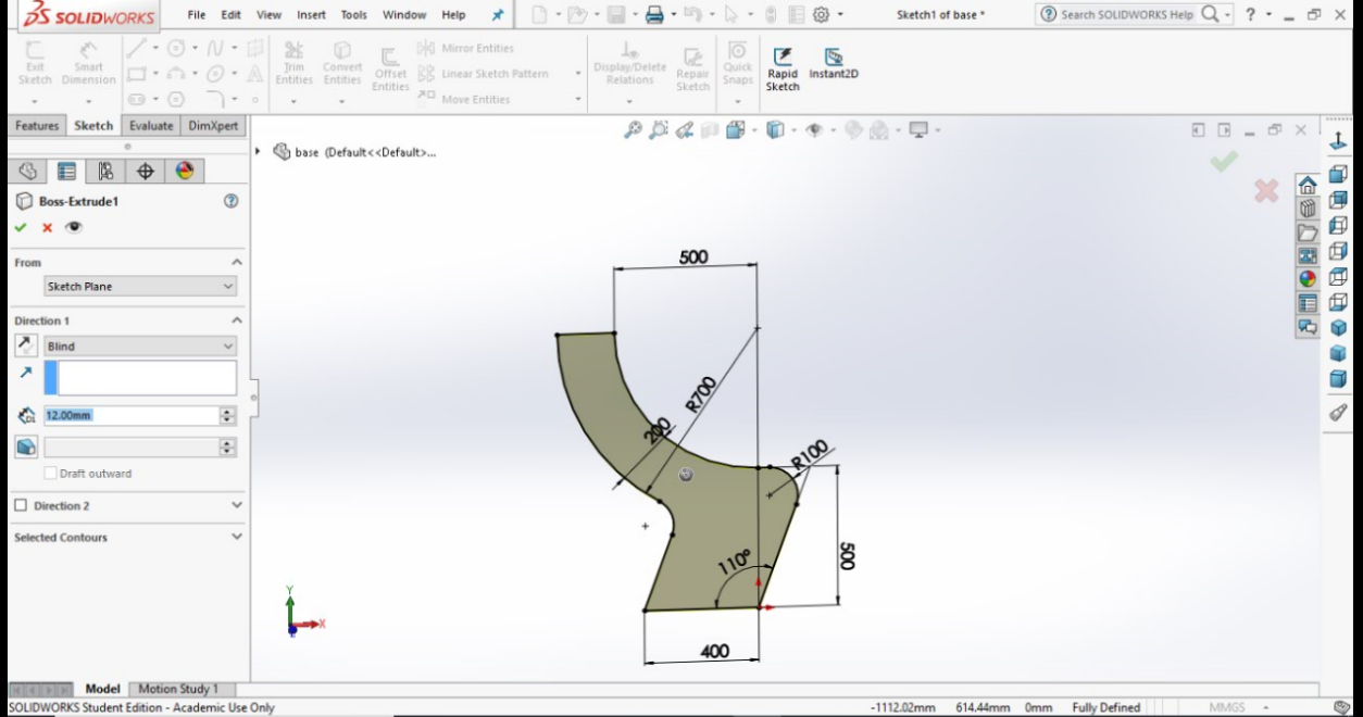
I have decided to use Solidwork software to design my chair. I started with the lines and dimensions I have chose the width to be 60 cms and height to be 90 cms.

I have made extrude with the thickness I have chosen which is 12 mm which the thickness of the plywood I am going to use. Despite I could have drawn it as 2D but I chose to make as 3D to make an assembly on the software. P.s when it's saved as DXF file it will be saved as 2D.
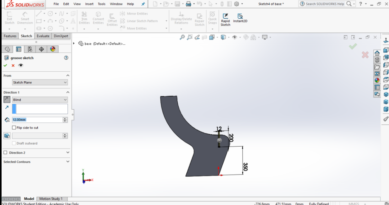
I have drawn the first joint opening with an opening of 12mm as the thickness of the plywood I have used.
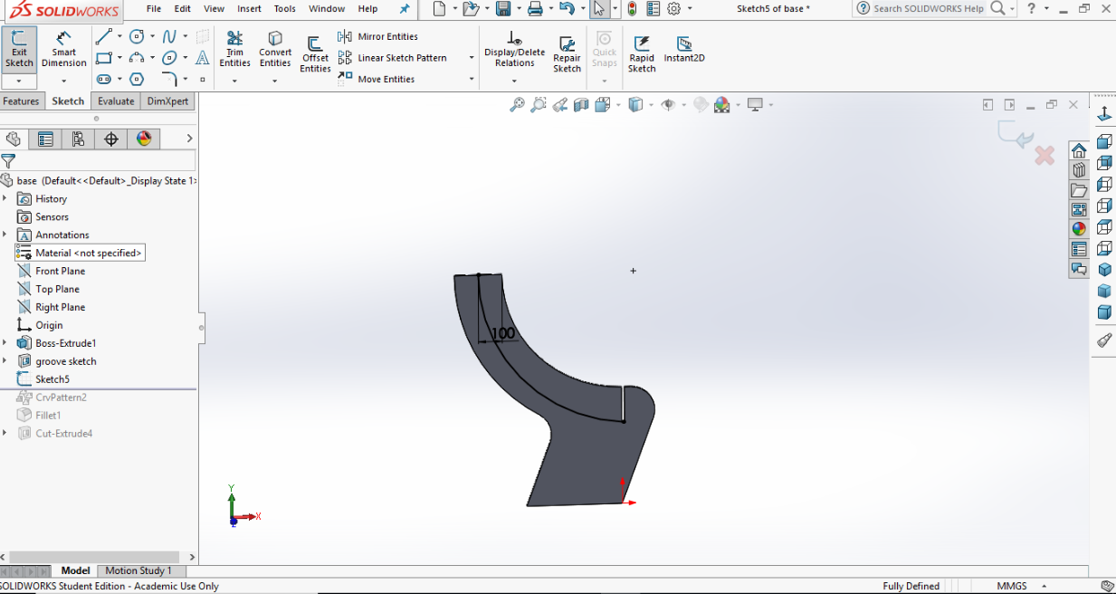
I have drawn a line across the curve.
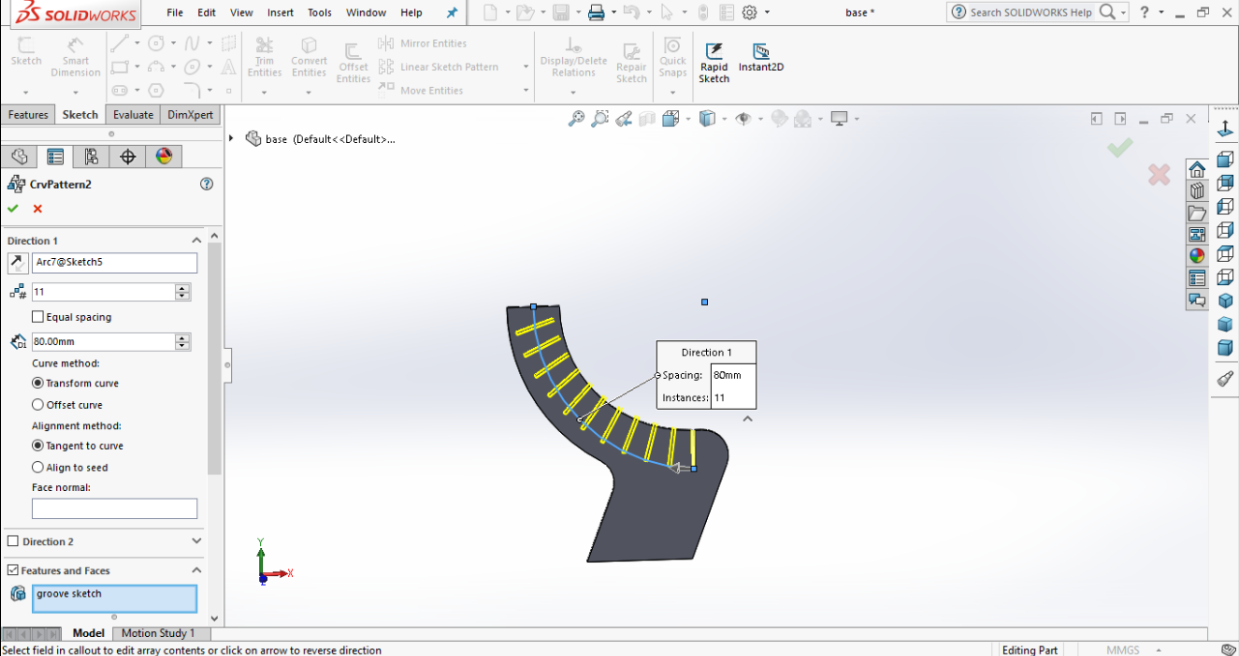
The line I have drawn in the previous picture so to be able to make a curve pattern. As you can notice you chose from curve pattern how many pieces you want and you must identify the access. The curve pattern will help in repeating the copies of the drawing.
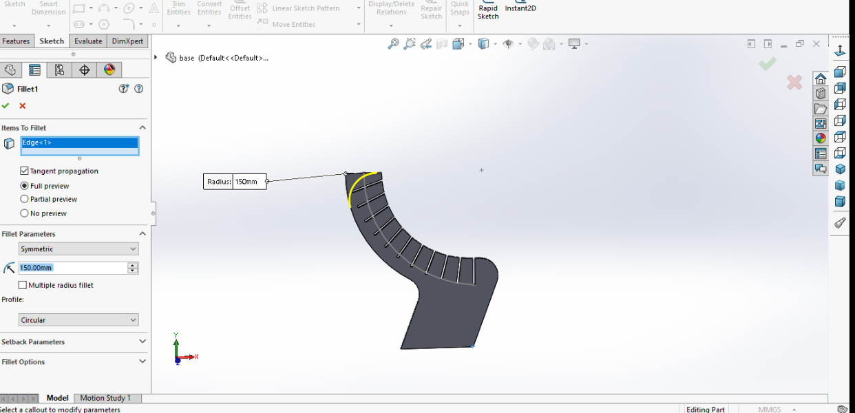
I have made a filet on the top with a radius of 150 mm.
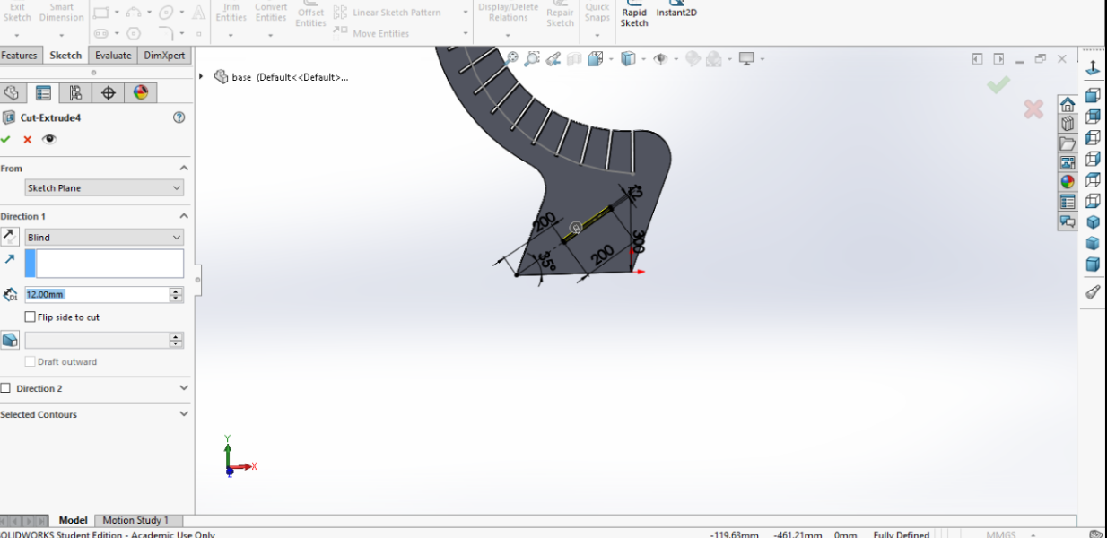
I have another joint opening in the bottom using cut extrude to be a support for the chair with the same thickness of the plywood of 12 mm.

I have made a drawing for the joint inner pieces with width of 60 mm and length 14 mm and will repeat 11 pieces of the same. It took some efforts as I drawn it using the lines.

This is the support piece which rectangle width 20 cms and length 52.4 cms.

Once you go to the assembly you can make the number of copies you want. So I have another copy for the side so now I have 2 sides also I have made 11 copies for the joint pieces.

I have used the Mate so to chose which surfaces to use so they can connect perfectly. It looked good after the assembly.
To make sure that it will stand perfectly and will hold a good weight when sitting on it I went to the center of mass as you can see.
Let's mill it
The machine we used
Shopbot
The CNC we have in our Lab is ShopBot. It is a powerful machine and one of the best Router. Despite I have participated in the assembly of this machine when we have first received at our Lab but I didn't have the time to work on it so I was so exicted to be able to work on it finally. Before I started working on it I made sure to wear all the safety equipments.
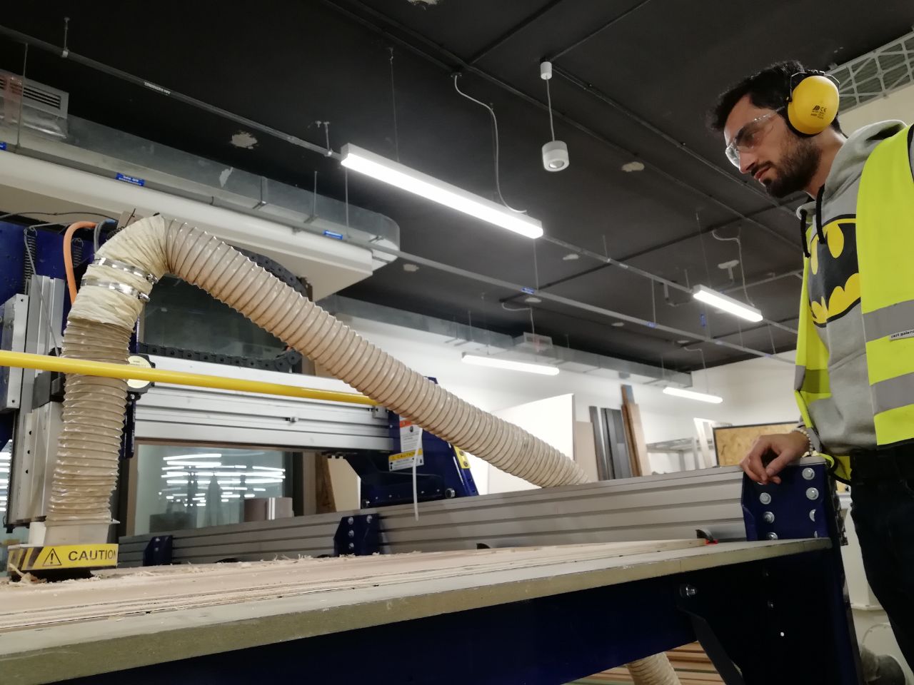
INTRODUCTION
Step 1. Saving Toolpaths
The above settings, are the ones I used. The spindle speed is set to 15000 r.p.m and is determined by the below equation:
spindle speed = (12 x the recommended peripheral velocity for the tool used)/(Pi x iameter of the tool in inches)
The feed rate is determined by the following equation:
Feed rate = Spindle speed x feed per revolution of the drill
The above chosen setting depends on the type of tool used, if we change the tool these settings will change as well as they have to be recalculated.
- In Aspire, in the right-hand panel, click the “Save Toolpaths” button.
- For now, check the "Output all visible toolpaths to one file" box, then check and highlight the toolpath you want to save. - Name your toolpath something so you can remember what bit to use and when to run it. This is the text engraving so I’ve called it CUT Repeat for other tool paths.
- If you change your file, you MUST recalculate the toolpath before saving
REMEMBER!
Step 2. Fixturing
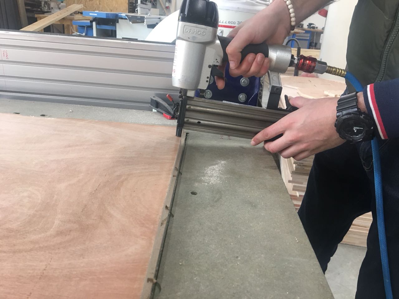
- There are two ways to fix the wood on the cutting table by screws or by using staplers I chose to use stapler. .
- Check to ensure that the bit will not hit screws or other fixtures.
- Drill a pilot hole to keep the material from "crawling" up the screws.
- Flat, level stock will save you a lot of trouble down the road.
- Below, MDF stock screwed onto to it. A test part has already been cut.
Step 3. Tool Changing
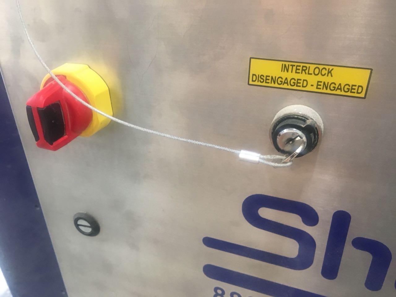
- Turn on the control box.
- Open ShopBot on the ShopBot computer.
- ShopBot has menus but runs best on the command line. To test this, type [K] (no brackets) and use the arrow keys to practice driving it around.
- Move the bit to the front of the bed where you can easily access it. Press PgUp to lift it about 8 inches away from the material.
- (UMBC ShopBot only) If the movement is noisy, that is not dangerous, but it will run faster and quieter using the settings in the final picture.
Step 7: X&Y Zero&Z-Zero
- Move back to the computer and drive the router to "Part Home", the point on the bed you want to correspond to the bottom left-hand corner/origin of your Aspire file. “Machine Home” is the corner of the ShopBot bed closest to the power switch.
- When you have driven to your Part Home, press [ESC], then type [Z2] to (z)ero on (2) the X&Y axis.
- Check in the red Position window that X and Y both read 0.000.
- Drive the router somewhere over your stock that you think represents a level part of the material.
- Remove the plate from the side of the router and clip the aligator clip onto the bit or onto to something electrically conductive to the bit. To double check this, look at the Input 1 indicator in the Position window. Tap the plate to the bit. If the light turns on when you touch the bit, you have conductivity.
- If the light is always on, you have attached the clip to something conductive to the plate and you need to move it to something conductive to the bit.
- Do NOT attempt to run the Z-Zeroing routine if the Input 1 light does not turn from OFF to ON when you tap the plate to the bit.
- Place the plate below the bit and type [C2] (Don't forget, you have to [ESC] out of the keyboard commands to do this.) You will receive a safety prompt, then the bit will come down, kiss the plate, pull back a little bit, then come back down more slowly.

The CAM process Vcarve
there are various software to make CAM with one is Fusion360 and Vcarve which was my choice to work with. I imported the pieces which were save as DXF and you start organizing them on the board in the best way so to save in materials when start the cutting. This is half of my chair again too save in the materials my colleagues had an empty space on their board so I have used these spaces for the rest of my chair. I identified all pieces then I chose VECTOR. Here you can choose out or inside cut I chose out cut for the entire design except the support opening; the out and inside must be save separately as they ill be different jobs. The jobs will be saved as G code. You can simulation and it will show you how it will work.
I used 2D Profile Tool Path to cut my chair, the settings are seen below:

Problems!
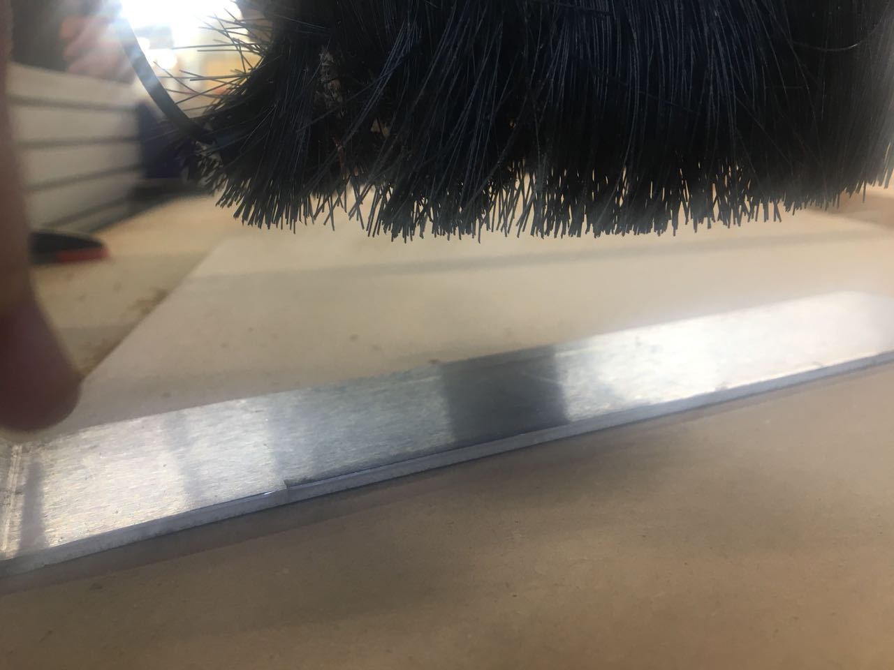
An idea about the machine while working. I have noted that the wood had some curve so I had to change the depth cut to 13.5 mm while the wood board thickness is 12 mm so to overcome the curving of the wood itself.
POST PROCESSING
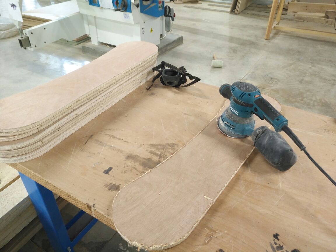
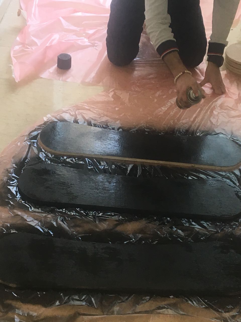
First I have made sanding for each part. make sure that your are wearing goggles when you are using the sanding machine. PAINTING. to have more even painting and quicker I used spray can which is a special quality of painting and protection layer.
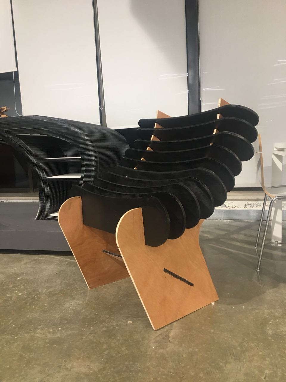
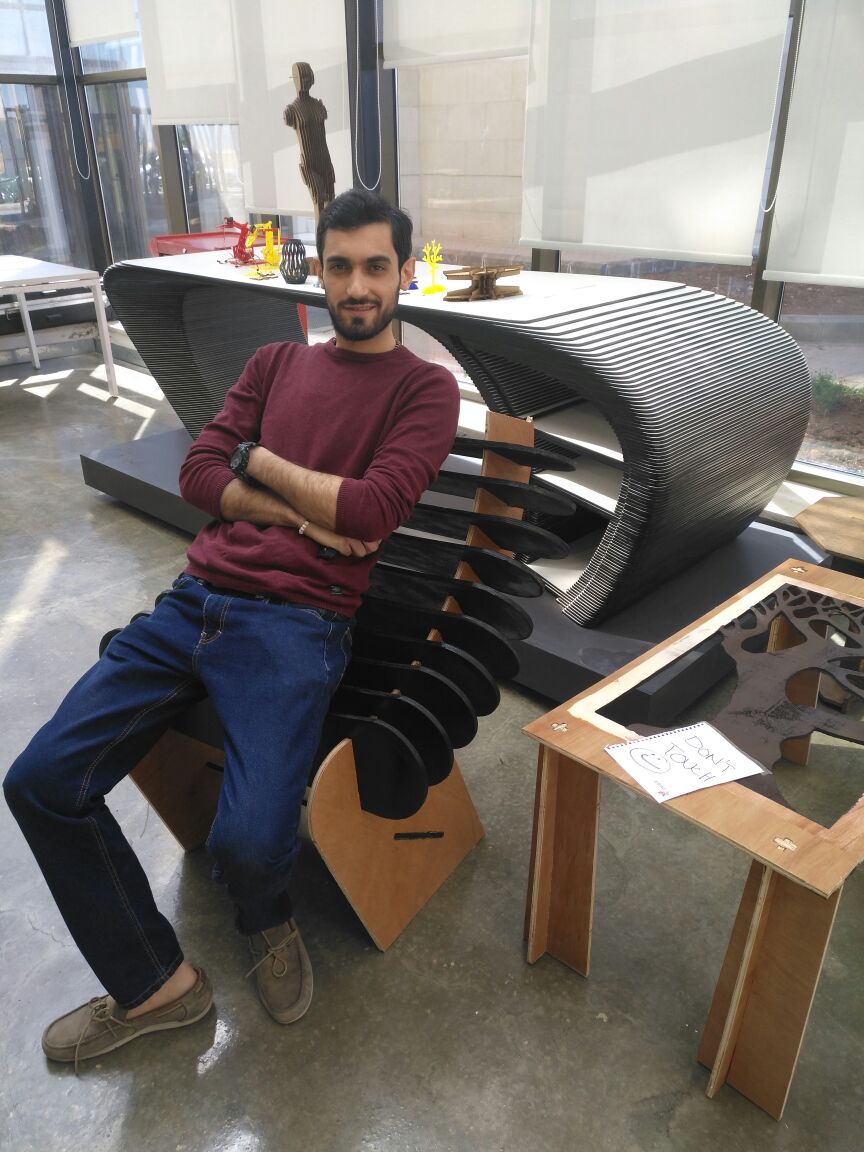
This is my chair finally made. Honestly I have never felt so comfortable sitting on a chair like this time after all I have made it(;
Download my chair