1.INTRODUCTION
This week was a REAL CHALENGE for me because I have a poor previous knowledge about programing and I have to do many things, so I decided to make a decomentation iclude many informations and resorses for me to improve my backgroung and understand more about programing.
The first thing we have to know about is the embedded system.
WHAT IS THE EMBEDDED SYSTEM?
An embeded system is a computer system with a dedicated function within a large mechanical or electrical system.
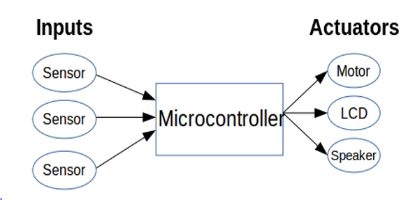
The embedded system components are:
1. Microcontroller.
2. Input devices like sensors, buttons.
3.Output devices sometimes called actuators and they are everything controlled by the microcontroller like motors,LCD,speakers....etc.
1.What is the diffrence between MCU and MPU
A microcontroller (sometimes abbreviated MC, UC or MCU) is a small computer on a single integrated circuit containing a processor core, memory, and programmable input/output peripherals.
A microprocessor (sometimes abbreviated MP, UP or MPU) incorporates the functions of a computer's central processing unit (CPU) on a single integrated circuit (IC, or microchip).
In simple words, microcontroller is a full fledged PC in a single chip! On the other hand, microprocessor is the CPU of the PC in a single chip!.
The simplest possible MCU based solution could be blinking an LED continuously at a specified time interval by programing the MC with c language.
In a MCU, most of the pins are digital GPIO pins (General Purpose Input Output pins). These digital pins can be turned on or off (or can be turned HIGH or LOW) as per the requirement, Not all pins are GPIO pins, there are some pins (like Vcc, GND, XTAL, etc) which are for other functions and cannot be turned on/off for interfacing.
GPIO have two modes:
- Output mode: It is quite simple. Setting it HIGH (1) gives an output of Vcc at that pin. Setting it LOW (0) gives an output of zero at that pin.
- Input mode: In this mode, the MCU can read the values at the pins. Here, a threshold is defined. Threshold voltage is usually half of Vcc. If a voltage above the threshold is read, it reads it as HIGH (1) or else LOW (0). For example, suppose our supply voltage Vcc = 5V. Hence, threshold = 2.5V. When we apply a voltage 5V, it reads as HIGH (as 5 > 2.5). When we apply a voltage of 0V, it reads as LOW (as 0 smaller than 2.5). Suppose 2V is applied. In this case, it will consider it as LOW (as 2 smaller than 2.5).
The input/output mode of GPIO pins is set by DDR register (which we will discuss later).
3.Port
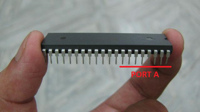
This is an important LINK has more information about pin configration, ports and AVR Peripherals.
Every single port has 3 registers, for example port X has 3 registers, where X = GPIO port name (A, B, C or D), and the registers are :
- DDR X
- PIN X
- PORT X
1. DDR X - Data Direction Register.
The GPIO pins are the digital I/O pins i.e. they can act as both input and output. Now, how do we know that the pin is an output pin or input? The DDRx (Data Direction Register) helps in it.
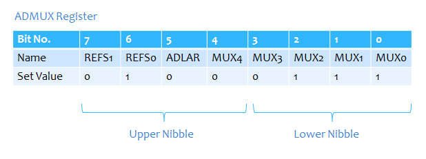
As shown in the register we have numbers from 0 to 7 which are 8 numbers as we have 8 pins of each port so every bit number has a value of 0 or 1 wich mean input for 0 and output for 1
Now to define the pins as I/O pins we declear that by DDRX= 0b01000111
2. PORT X - Pin Output Register
The PORTx register determines whether the OUTPUT should be HIGH (1) or LOW (0) of the OUTPUT PINS. In simplified terms, once the DDRx register has defined the output pins, we need to set them to give an output of HIGH or LOW.
3. PIN X - Pin Input Register
The PINx register gets the reading from the input pins of the MCU.
After reading the above this is a link for a good tutorial about How to access Input / Output Ports
5.Make tool and Makefile
Make tool is used to translate the sorce codes that related to c/c++ languages and this tool mostly used in the diifrent operation systems even windows, Make tool commonly used in linux/osx systems.
BUT what is this tool and what is the benefits of using it ????
This tool helps to faster the execution of the translation process for the sorce codes. So if there was 100 sorce files and after the translation process(COMPILING) the program had become executable.
If the programmer want to edit or add some codes inside one of the sorce files, he have to program all the sorce codes that depends on that single file again, and that needs a lot of time without considering the compiling time for the sorce codes that needs time depends upon the program size, as some programs takes more than 40 minutes.
Because of that the benefit of MAKEFILE come here in which helps the programer to compile just the files that he had edited and the files that depends or related to the edited file.
The meaning of dependency, for EXAMPLE we have file number 2 depends on file number 6 so that if the file number 6 is modified then the amendment will be made to file 2.
HOW TO TRANSLATE THE SORCE CODEVBY USING COMMAND LINE?
For linux/osx users through Treminal you can use the special translator (COMPILER) for C/C++ languages, and this compiler KNOWN AS g++/gcc in which:
gcc compliler used to translate the sorce files in C language
g++ compiler used to translate the sorce file in C++ language.
A compiler is a special program that processes statements written in a particular programming language and turns them into machine language or "code" that a computer's processor uses. Typically, a programmer writes language statements in a language such as Pascal, C or C++ one line at a time using an editor.
This is an example for translate a sorce code in C++ through terminal:
We assume that we have the following files :main.cpp
fun1.cpp
fun2.cpp
Note: A CPP file contains C++ programming code you must compile before you can run the file's code on your system linux/osx. in windows You use Visual Studio to compile the CPP code. The compiling process creates an EXE file, which is an executable that runs on a Windows computer.
For translate this files and naming the executable programe of it as program we tap this commant in the terminal
OmenT$ g++ main.cpp fun1.cpp fun2.cpp -o program
to execute the program
OmenT$ ./program
Now to make the "Makefile" in which it it will used in make tool to translate the source codes we have to learn
How to write the "Makefile"
The first thing is to creat a text file with a name of "Makefile" with considering the first alphabet is capital "M" (GNU the devloper of make tool advice to write the first alphabet capital)
NOTE: there is no extension for this file, but it is considered a text file.
In LINUX system you dont have to add extension.
In OSX you can create a text file and give it a name of Makefile, some text editors like sublime text gives the extension .make, so that the file name is Makefile.make here you need to use -f option when you execute the command make and determine the file name with its extension to enable the tool to execute file commands.
Rules of writting the "Makefile"

1. Target: a name is determined by the programmer, then the programmer called the name through the tool make in terminal in which the tool execute the command in "system command", often the names of the binary files is for the source files.
2. Dependencies: in case there is a dependencies A dependency is a file that is used as input to create the target. A target often depends on several files.
3. system commands: here the tranlation commands is written through the translator g++ as in the previous example.
It is known when translating any source file through the translator(compiler) there is options to translate it, so that the source code is converted to a binary code (byte code) and the extension of this binary code is .o, after converting the source file to binary, it is converted to an exutable file by taping the option -o in the compiling command.
Simple example on writting make file
compile :
g++ main.cpp fun1.cpp fun2.cpp -o program
In this simple example there is no dependency files so it is just compile all the files to explain ho to make "Makefile", after we saved the file, tap this command in the terminal:
OmenT$ make compile
Now we determine the target, in this example the target is "compile" so that you tell the tool make to execute the command inside the target.After execute this command, an executable file will be generated which is program.
Mostly when not tapping the name of the target the tool will execute the first target in the "Makefile", usually the line has translation for all the source codes,based on the required dependencies files before executing the command to generate the program.
Example with more details of Makefile
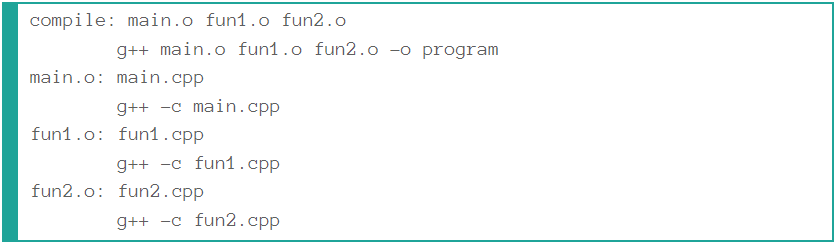
In this example we have 4 targets which are :
1. compile
2. main.o
3. fun1.o
4. fun2.o and every target has a dependencies and commands
If we tapped make compile in the teminal what will happen?
The make tool will check the existence of the dependencies files and they are (main.o fun1.o fun2.o)
so the tool will moves to main.o in which it has the dependencies file main.cpp since this file is existed the make tool will execute main.o command and thus continue to execute all the dependencies files until all the dependencies files are completed, after that it will execute the command of compile.
this is a helpful links about Makefile:
LINK1
LINK2
There are 3 bytes of permanent storage in the chip called 'fuse low byte', 'fuse high byte' and 'fuse extended byte'. These bytes are called fuses and can be reprogrammed as many times as you want and determines the behaviour of the chip. To do that, their value is not erased when the chip is powered off or reprogrammed.
Each microchip has its own definition for the values that must have the fuses.
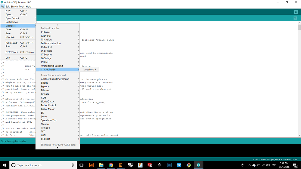
7.Programming Using Arduino ISP
From the examples I chose arduino isp
Then I selected the board as Arduino/Genuino Uno and i uploaded the file to arduino
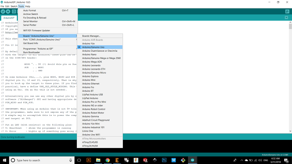
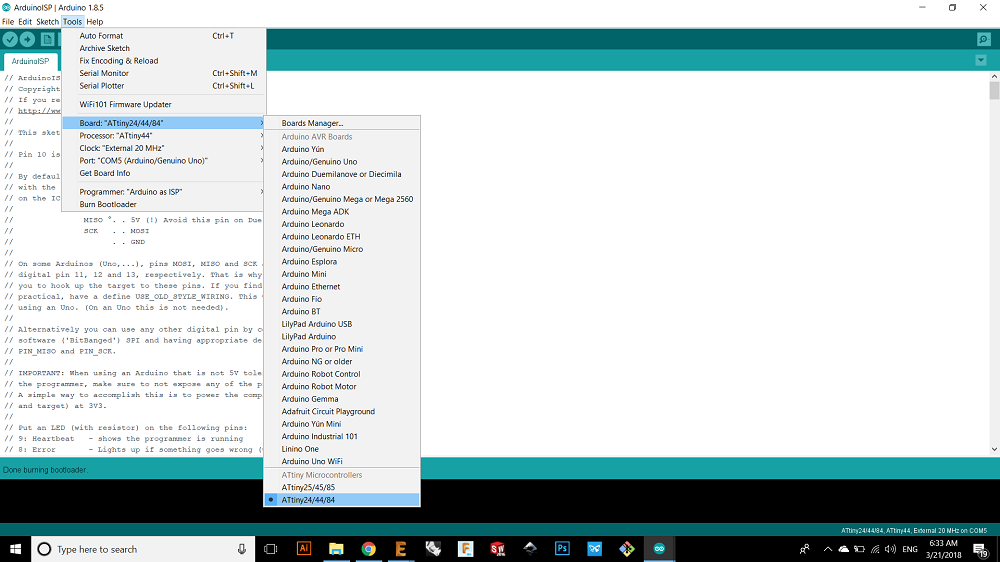
Now I connected my board with the arduino and I chose the board, processor and clock and then burn bootloader.
 br>
br> 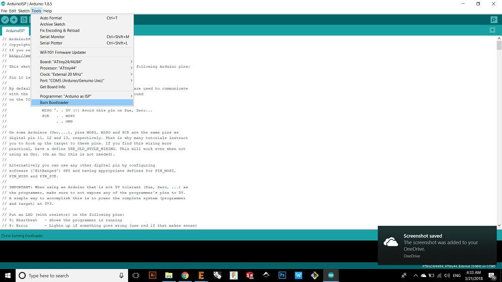
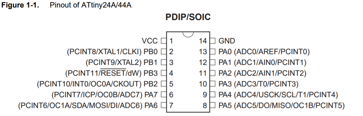
then I chose blink example and I made some edits on it, here I defined the led as 7, in my board it was pin 6 but in arduino bin 7
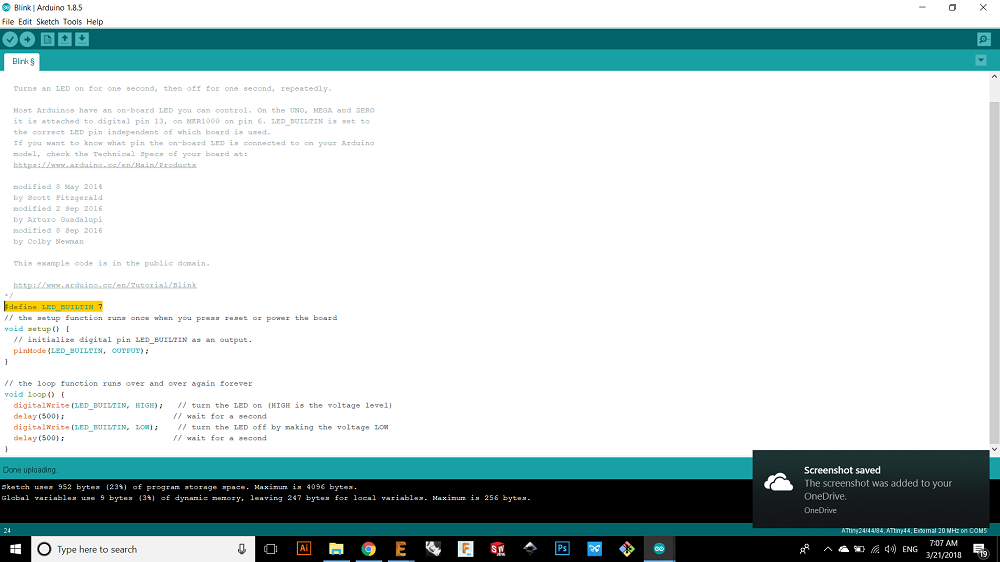
the I chose the delay time of half second
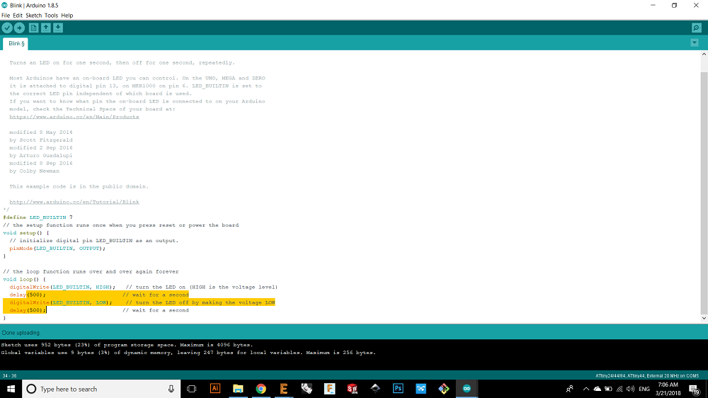
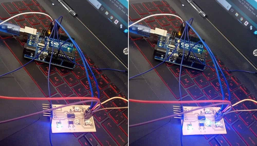
Here is my board blinking
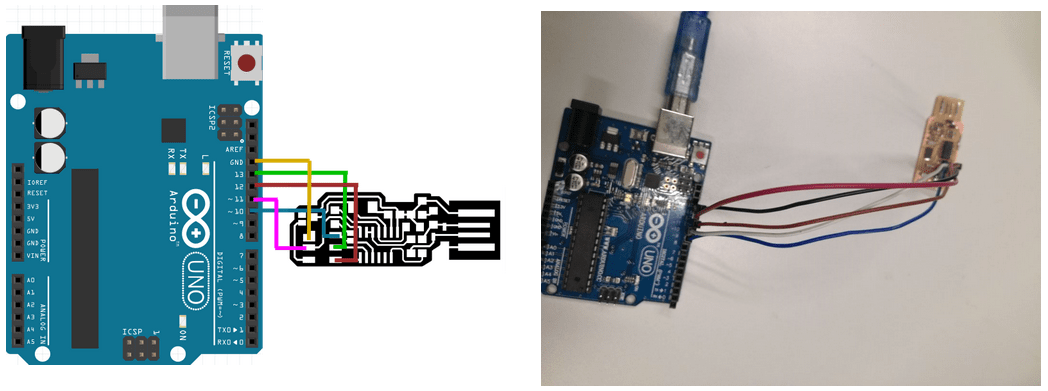
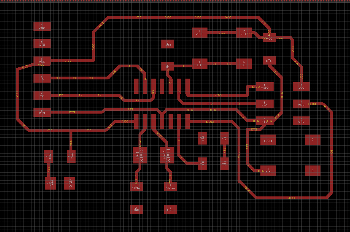
8.Programming Using Fab ISP
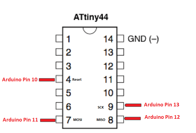
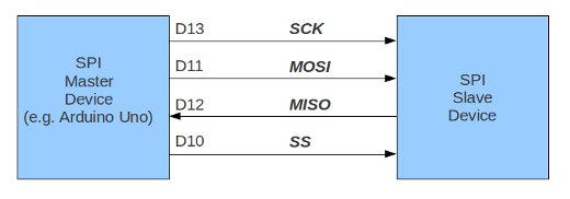
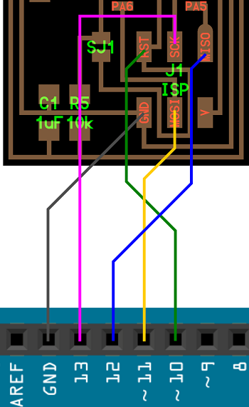
Now I will program my board using fab isp so that the connection between them will be as following:
VCC with VCC
MOSI with MOSI Master-out, Slave-in. This line carries data from our Arduino to the SPI-controlled device(s);
MISO with MISO Master-in, Slave out. This line carries data from the SPI-controlled device(s) back to the Arduino;
GND with GND
SCK with SCK Serial clock.
Within these section we consider the SPI board to be the master and the hello board to be slaves.
Easy peasy lemon squeezy
It is the time now to enter the practical side of programing, it's the time to program our fucking board, yes WE ARE THE PROGRAMMERS
Now we need 3 important things and they are :
- The source code which is written in C language.
- Make tool and Makefile.
- AVR libraries - which I can download like I did before when I programmed the ISP.
Now we need to followed this steps:
First we need the source files which is written in C language in order to blink the LED.
THIS IS MY C code
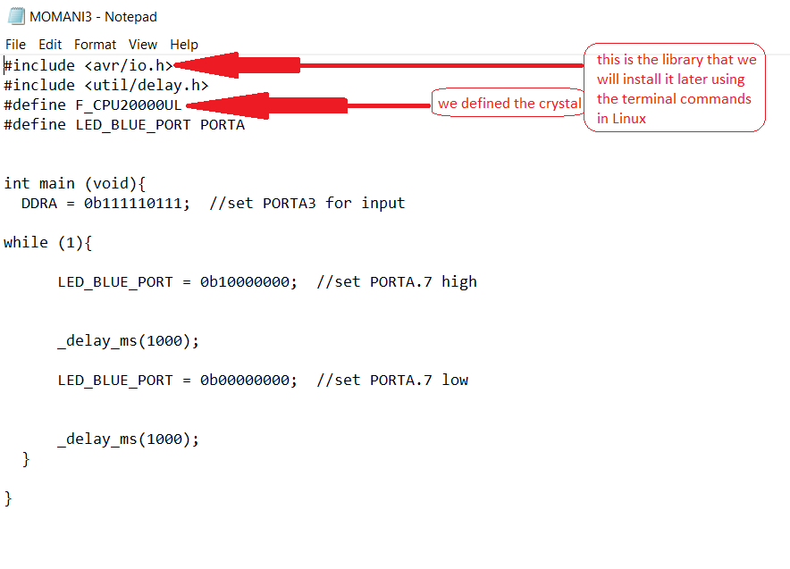
As the files are written by C we will use the gcc translator(compiler) in the treminal to compile the file in Linux.
Then we will tape the avrdude command using Linux terminal to upload the executable file to our hello board.
We can get the "Makefile" from Neil's example and then I edited it, and here is my Edited Makefile
It is the time to start using ubinto, the first thing to do is to install the libraries by the following commands:#declear the variables PROJECT=MOMANI3 SOURCES=$(PROJECT).c MMCU=attiny44 F_CPU = 20000000 CFLAGS=-mmcu=$(MMCU) -Wall -Os -DF_CPU=$(F_CPU) #create set of parameters for the compiler (clock, MCU) of the variable FLAG so in this case we dont have to add the parameters in each system command. $(PROJECT).hex: $(PROJECT).out avr-objcopy -O ihex $(PROJECT).out $(PROJECT).c.hex;\ #In the all system commands we have to consider the tap space, every command has a tap space, this command to copy and translate object files avr-size --mcu=$(MMCU) --format=avr $(PROJECT).out #size utility lists the section sizes $(PROJECT).out: $(SOURCES) avr-gcc $(CFLAGS) -I./ -o $(PROJECT).out $(SOURCES) # we used the gcc compiler to compile the source file which written in C program-usbtiny: $(PROJECT).hex avrdude -p t44 -P usb -c usbtiny -U flash:w:$(PROJECT).c.hex #to upload the executable file program-usbtiny-fuses: $(PROJECT).hex avrdude -p t44 -P usb -c usbtiny -U lfuse:w:0x1F:m #to upload the settings of the fuses
sudo apt-get install flex byacc bison gcc libusb-dev avrdude
sudo apt-get install gcc-avr
sudo apt-get install avr-libc
sudo apt-get install libc6-dev
After installing the libraries I made the hex file by typing make then I called the target "program-usbtiny" you can follow my terminal here :
     ubuntu@ubuntu:~/Desktop/moath$ lsusb
Bus 002 Device 001: ID 1d6b:0003 Linux Foundation 3.0 root hub
Bus 001 Device 005: ID 8087:0a2a Intel Corp.
Bus 001 Device 004: ID 04f2:b56d Chicony Electronics Co., Ltd
Bus 001 Device 012: ID 1781:0c9f Multiple Vendors USBtiny
Bus 001 Device 003: ID 0781:5567 SanDisk Corp. Cruzer Blade
Bus 001 Device 013: ID 2341:0043 Arduino SA Uno R3 (CDC ACM)
Bus 001 Device 001: ID 1d6b:0002 Linux Foundation 2.0 root hub
ubuntu@ubuntu:~/Desktop/moath$ pwd
/home/ubuntu/Desktop/moath
ubuntu@ubuntu:~/Desktop/moath$ ls
Makefile  MOMANI3.c
ubuntu@ubuntu:~/Desktop/moath$ make
avr-gcc -mmcu=attiny44 -Wall -Os -DF_CPU=20000000 -I./ -o MOMANI3.out MOMANI3.c
avr-objcopy -O ihex MOMANI3.out MOMANI3.c.hex;\
avr-size --mcu=attiny44 --format=avr MOMANI3.out
AVR Memory Usage
----------------
Device: attiny44

Program:     104 bytes (2.5% Full)
(.text + .data + .bootloader)

Data:          0 bytes (0.0% Full)
(.data + .bss + .noinit)


ubuntu@ubuntu:~/Desktop/moath$ make program-fabISP
avr-objcopy -O ihex MOMANI3.out MOMANI3.c.hex;\
avr-size --mcu=attiny44 --format=avr MOMANI3.out
AVR Memory Usage
----------------
Device: attiny44

Program:     104 bytes (2.5% Full)
(.text + .data + .bootloader)

Data:          0 bytes (0.0% Full)
(.data + .bss + .noinit)


avrdude -p t44 -P usb -c usbtiny -U flash:w:MOMANI3.c.hex

avrdude: AVR device initialized and ready to accept instructions

Reading | ################################################## | 100% 0.00s

avrdude: Device signature = 0x1e9207 (probably t44)
avrdude: NOTE: "flash" memory has been specified, an erase cycle will be performed
         To disable this feature, specify the -D option.
avrdude: erasing chip
avrdude: reading input file "MOMANI3.c.hex"
avrdude: input file MOMANI3.c.hex auto detected as Intel Hex
avrdude: writing flash (104 bytes):

Writing | ################################################## | 100% 0.13s

avrdude: 104 bytes of flash written
avrdude: verifying flash memory against MOMANI3.c.hex:
avrdude: load data flash data from input file MOMANI3.c.hex:
avrdude: input file MOMANI3.c.hex auto detected as Intel Hex
avrdude: input file MOMANI3.c.hex contains 104 bytes
avrdude: reading on-chip flash data:

Reading | ################################################## | 100% 0.15s

avrdude: verifying ...
avrdude: 104 bytes of flash verified

avrdude: safemode: Fuses OK (E:FF, H:DF, L:FE)

avrdude done.  Thank you.
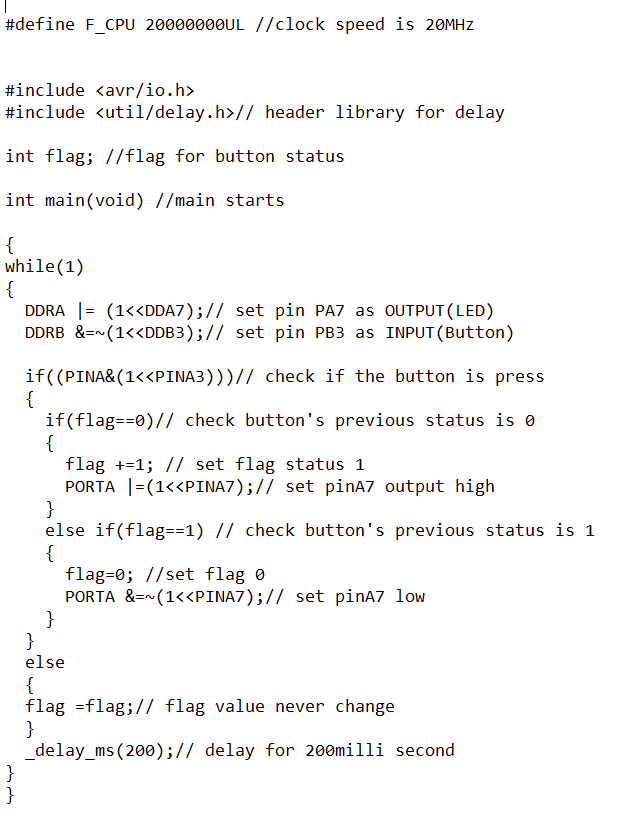
Now Im goiung to upload the second C code
In this code if I pressed and hold the input button which is in portA3 then the led in portA7 which is output pin will start blinking
And here is the Makefile
Proof
here is the 3rd C code and its Makefile, hex file and out file
here is the code
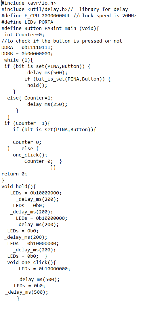
In this code if I pressed the input button which is in portA3 one time the led in portA7 which is output pin will blink once, and if I pressed and hold the led will blink 3 times.
Proof