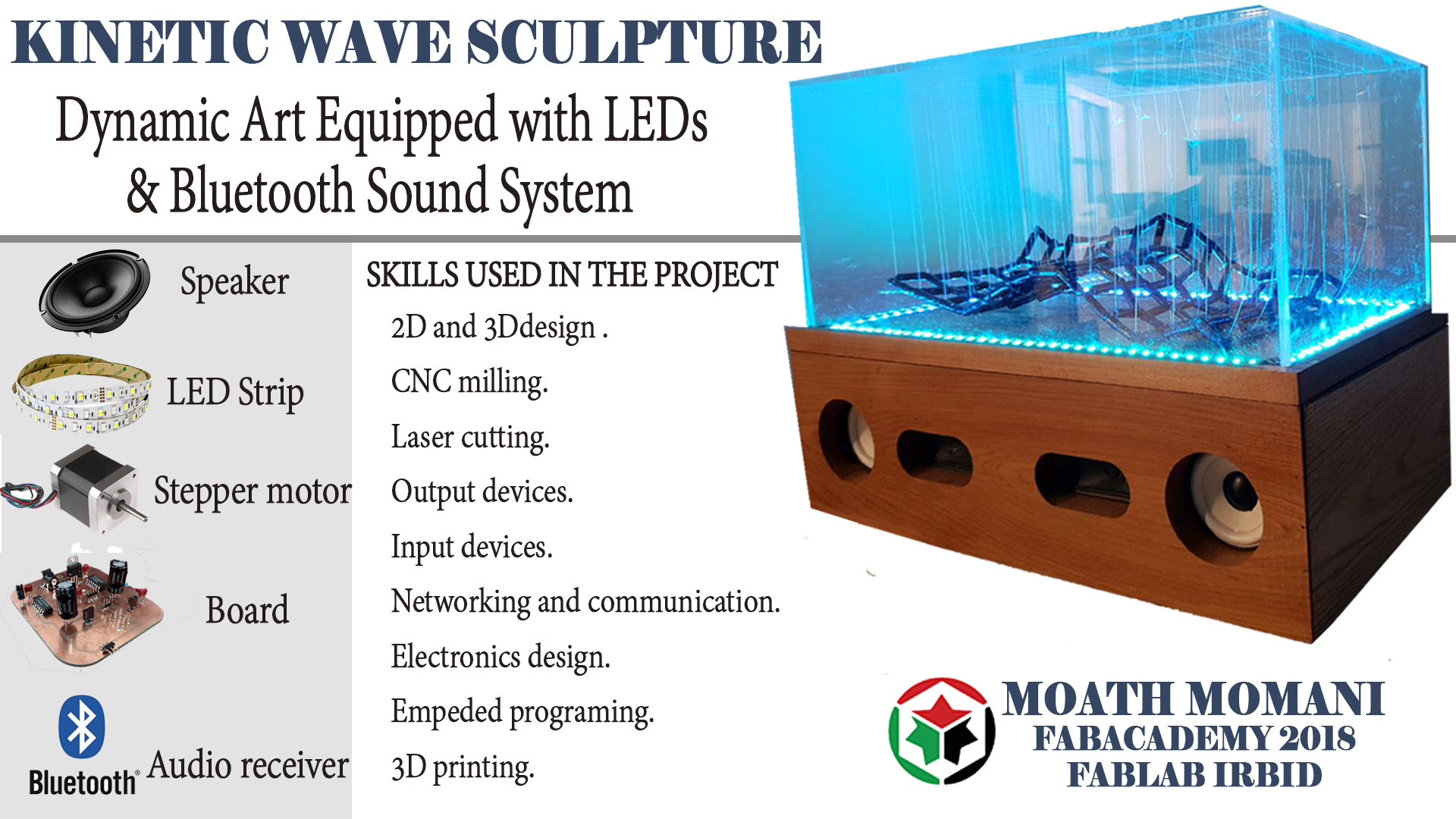
INTRODUCTION
So what I'm going to do is a kind of art that contains movement perceivable by the viewer or that relies on motion for its effect—this is the definition of kinetic art. While the definition explains the practical notion, it doesn't emphasize the hypnotic capabilities of the art form. And though it comprises any medium, it's actually a kinetic sculpture that most comes to mind when thinking of the genre.
I chose to make this prototype because maybe in the future, I can open a company and get money from it, because my project has a big target like the hotels, restaurants, malls and all the celebration places and in the country there is no company doing this until now.
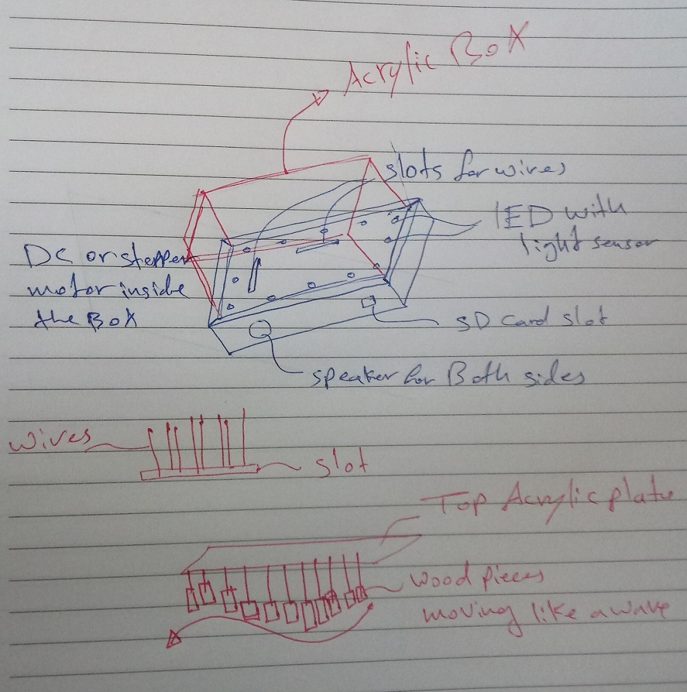
The mechanism of my project depends on the motion of many wires connected with each other so if a special rotation happened to the wires, then the particles will start moving like a wave and this is a picture showing a simple system for the sculpture
.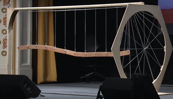
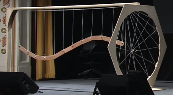
So imagine this as a movable floor! that would be amazing
And this sclupture also working with the same mechanism.

Materials, Components will be used and Project Cost
This table contains all the components and information about it
| Components | Name | Datasheet/info | Price |
|---|---|---|---|
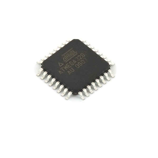 |
Atmega328p | Data sheet | 4 |
 |
Nema17 stepper motor | Data sheet | 20 |
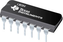 |
LM384N | Data sheet | 3 |
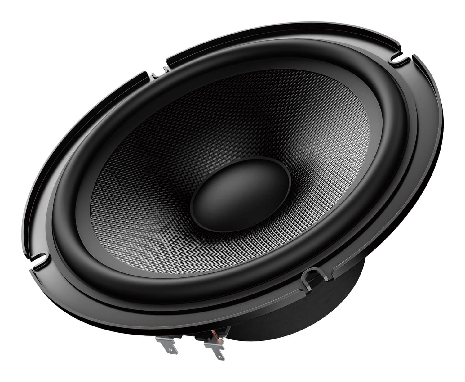 |
Speakers | 5w Speaker | 8 |
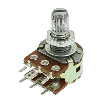 |
Potentiometer | 6 pins potentiometer | 0.75 |
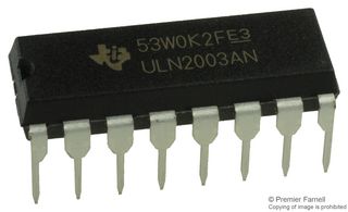 |
ULN2003AN | Data sheet | 3 |
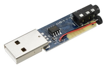 |
Blutooth Audio receiver | 5 volts audio receiver blutooth | 5 |
Materials I want to use :
- Oak Woodand the coast is 30 dollars
- Acrylic 8mm thickness and the coast around 30 dollars
- PLA 3D printing and the coast of the part is 15 dollars
1.Sound System
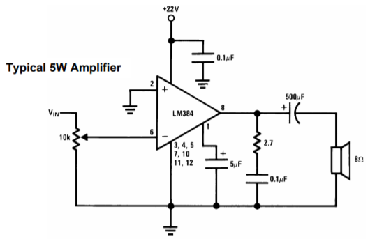
Also in my project I want to make a sound system to play music with the wave motion so I want to integrate a Bluetooth module in order to play the music from my phone but first I have to make the amplifier circuit, for my project it more than enough to use 5 Watt/8 ohm speaker so I have made a research about amplifier IC so I found LM384N
And here is the pins out
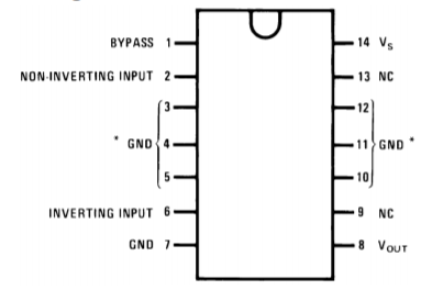
Some Important Features
• Wide Supply Voltage Range: 12V to 26V
• High Peak Current Capability: 1.3A
• High Input Impedance: 150kΩ
• Low Distortion: 0.25% (PO=4W, RL=8Ω)
From data sheet I'm goin to use this circuit
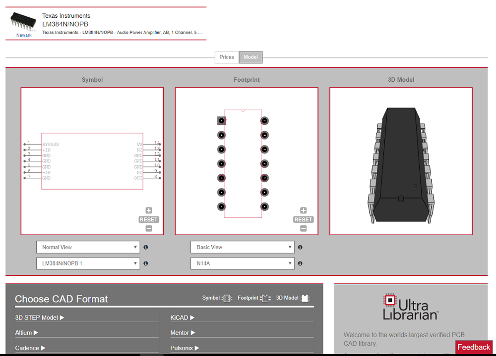
To design the PCB for my IC I need to install the library of LM384 so I went to ultralibrarian.com and I found LM384 library
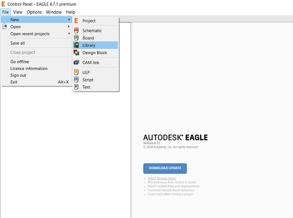
After I installed the library I opened eagle
In the control panel window, I selected File -> New -> Library from the menu.
In the blank library window, select File -> Execute Script from the menu.
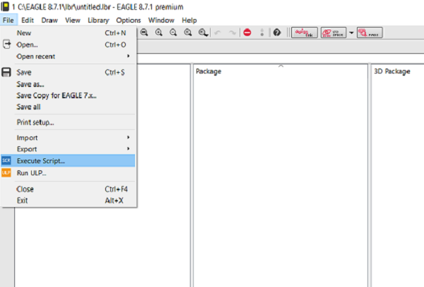
I Browses the newly exported Eagle Script file (".scr" file extension)
After opening the file, the script will populate the new library.
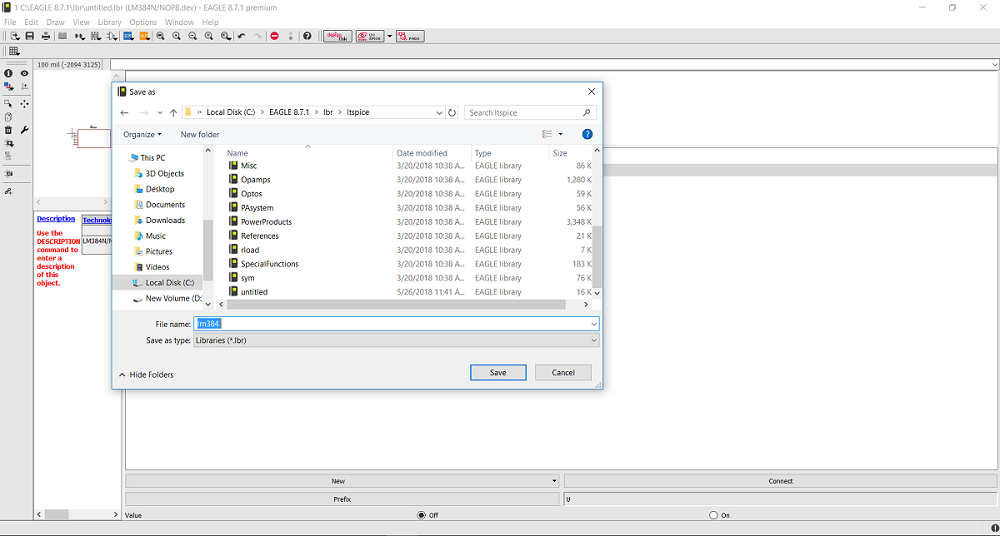
To save the library I Saved the file As lm384 to the desired location in Eagle native format.
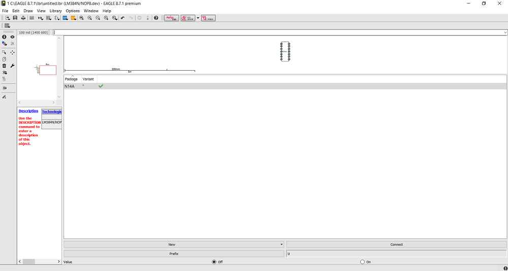
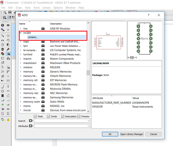
I opened a new schematic and I opened the library from library manager and here is the library
Now I started the design with two IC because I want to add two speakers left and right and I want to play the music (inverting input) by two ways:
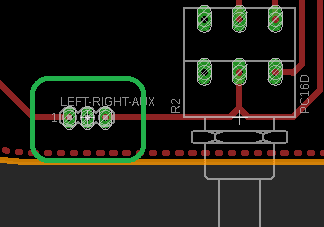
The first way by using AUX cable so I integrated two pins in my board for the left and right input and GND pin as the AUX cable has 3 wires and they are left-right-ground as shown.
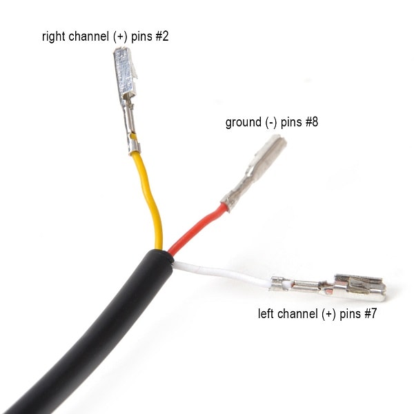
So I can play the sound from my phone
The second way by using a blutooth audio receiver
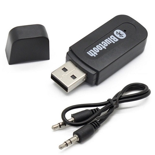
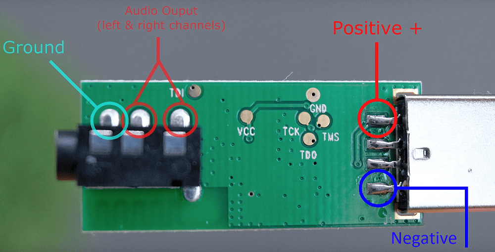
As shown the Bluetooth module has a USB plug at one end, but this is only for power as it has 5V so when I connect this module with power it receive an audio signal wirelessly via Bluetooth, so what I did I removed the USB and I soldered two wires to the VCC and the GND also I soldered 3 wires which they are left-right-ground
Now I want to make a circuit for testing the LM384N by using breadboard in the first time I will play the music by the AUX cable and next with the blutooth module, here we go
This video shows the circiut of the amplifiere in the breadboard, when I played the music the sound was perfect!!
Next I played the music via blutooth BUT there was a problem a nasty noise happened !!!
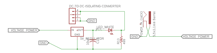
Destortion happened!! this problem happened because something called GROUND LOOP and fixing it needs DC to DC isolating converter and without it the board will create a nasty interferance noise!!
It takes a 5v input and then outputs it as a nother completely independent of 5 volts supply and its place between the voltage regulator 5v and the blutooth module and then the left and right output go to the potentiometer.
So in my board I designed pins for the Bluetooth, DC to DC isolator, also I equipped a 6 pins potentiometer to control the sound level for left and right speakers
Here is my schematics and board layout
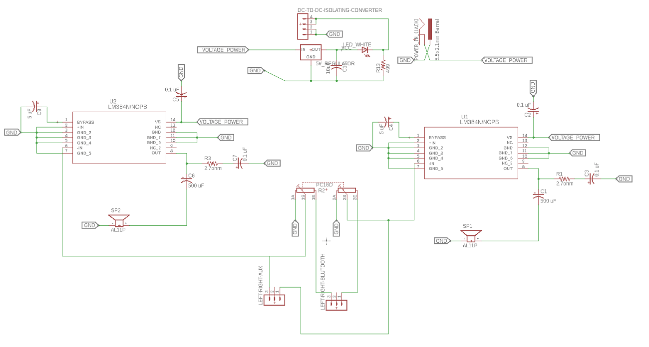
You can see in the schematic I have designed two microcontroller lm384n, one for right speakers and the second for the left speakers
In the schematic I have also designed a voltage regulator circuit 5 volts to output a 5 volts to the dc to dc isolating coverter and then the 5 volts feeds the blutooth module
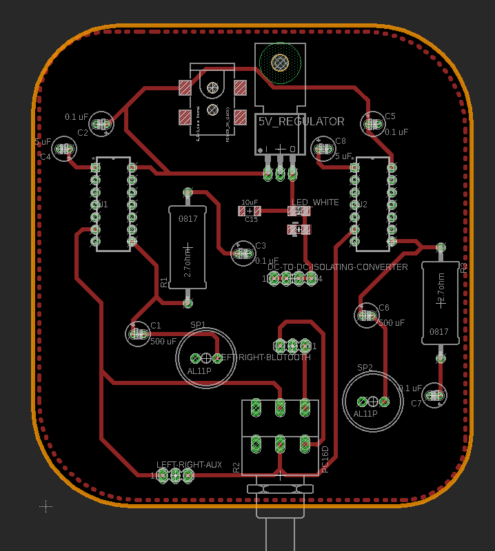
I also designed 3 pins for the AUX couple left, ground and right, so you can play the music from this cable, but in my case I but the aux cable with the Bluetooth module also I designed a 6 pins potentiometer to control the volume of the right and left speakers but in my project I didn't put a potentiometer because I can control the volume from my phone or laptop with Bluetooth
For more information about the electronics design and eagle software go to this Link
Download board Schematic and board Layout
Now Im going to mill the board by using Roland SRM 20 but firs I need to generate the tool path
The CAM software that I will use to generate the toolpath for the PCB is Flatcam
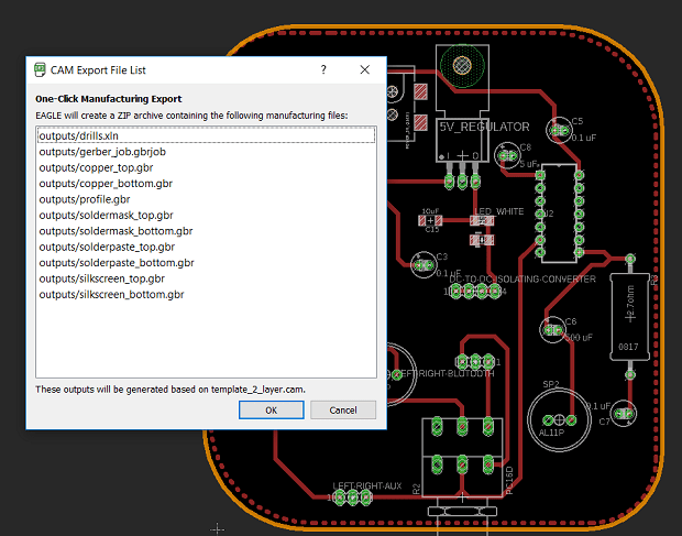
In order to use flat cam I have to get the cam files from eagle - Board layout - file - generate cam date
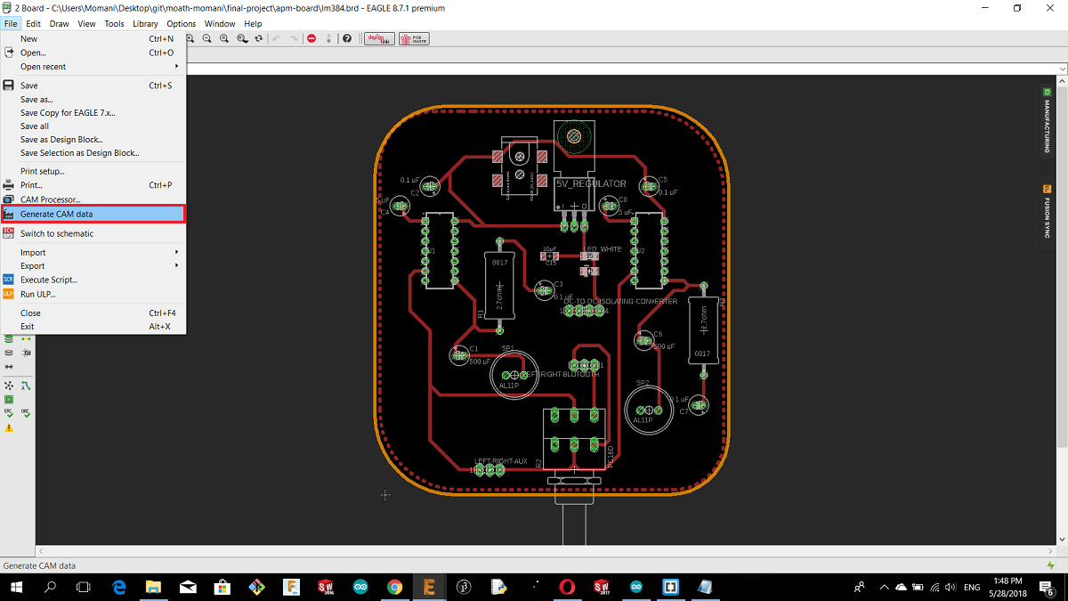
And this is the Gerber and Eexellon files that I will get in a zip file .
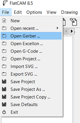
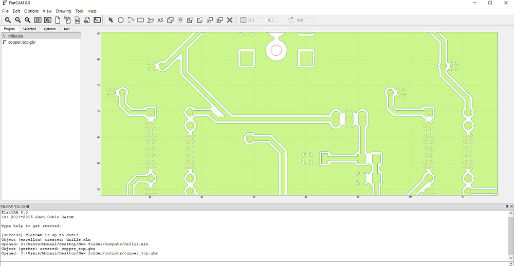
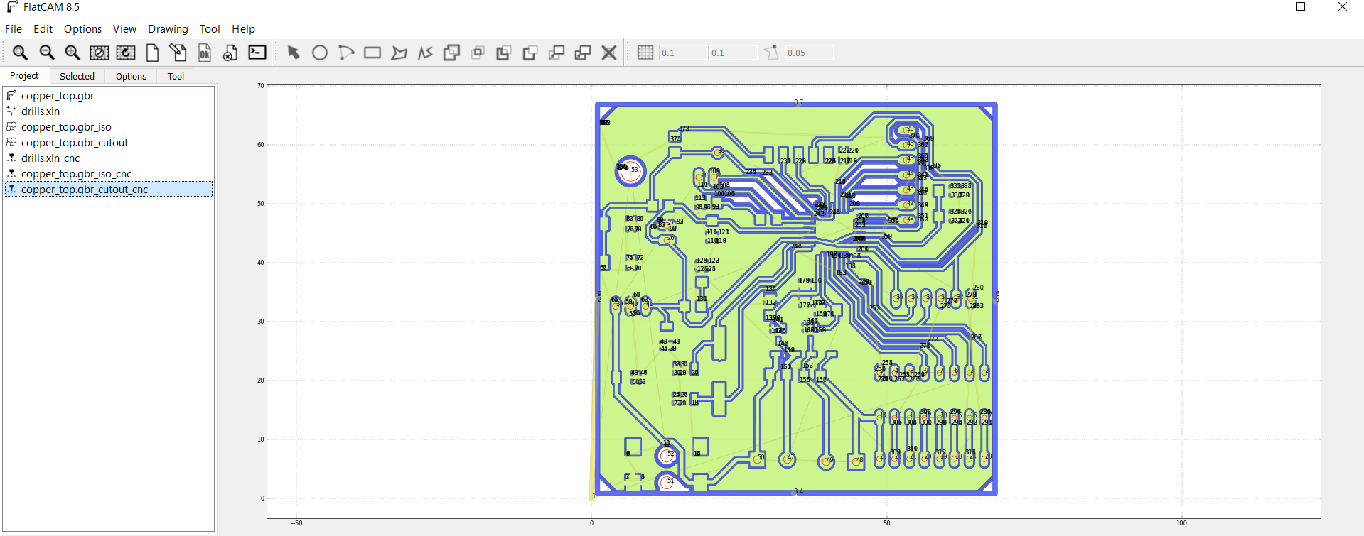
After I extracted the zip file I opened flat cam, from file I chose open Gerber file which means I opened the file that contain the traces and the board outside cut, then I chose an open Exellon file which mean I Opened the file that contain the holes that I want to drill.
The first thing I did Is to open flat cam software then from file menue I chose open Gerber
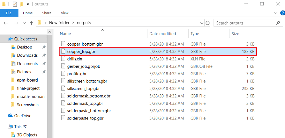
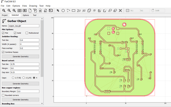
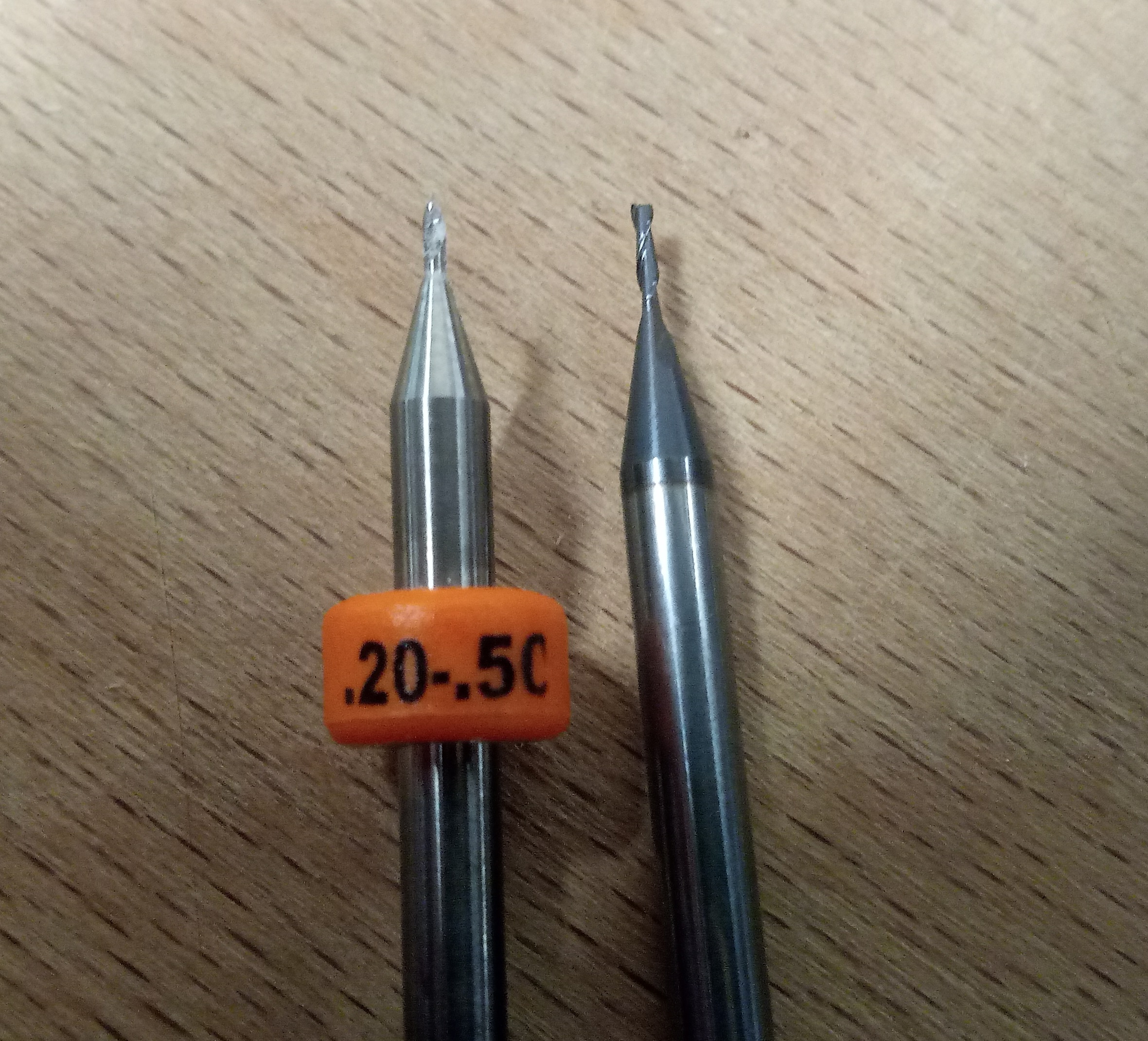
Then I selected cupper top in order to make the tool path for inside cut for the traces by 0.2 solid carbide end mill and the outside cut by 0.79 flat endmill
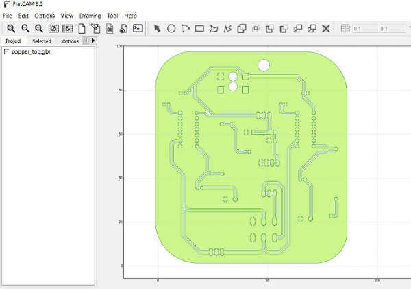
After I opened the selected file this is how its look like
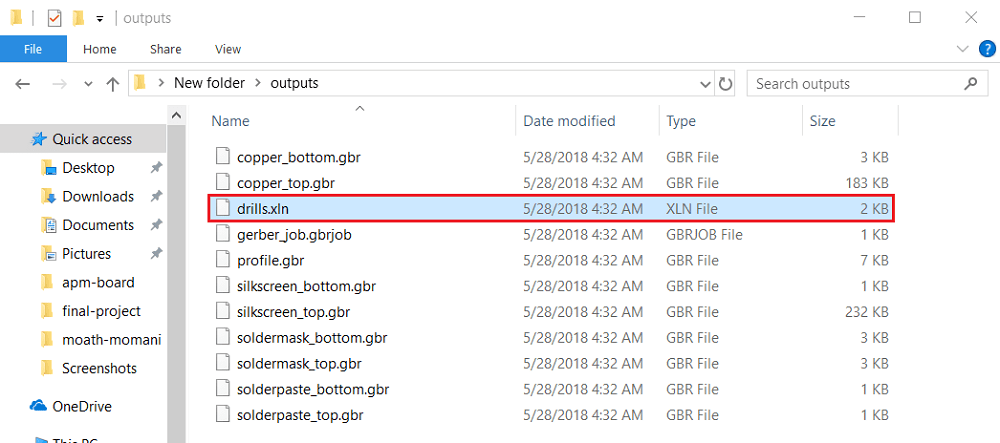
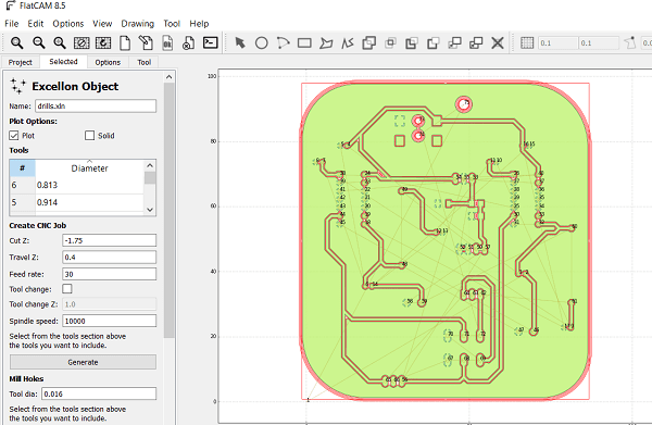
The second step is to open the Exellon file
After I opened the Exelon file this is the red lines as shown for the holes
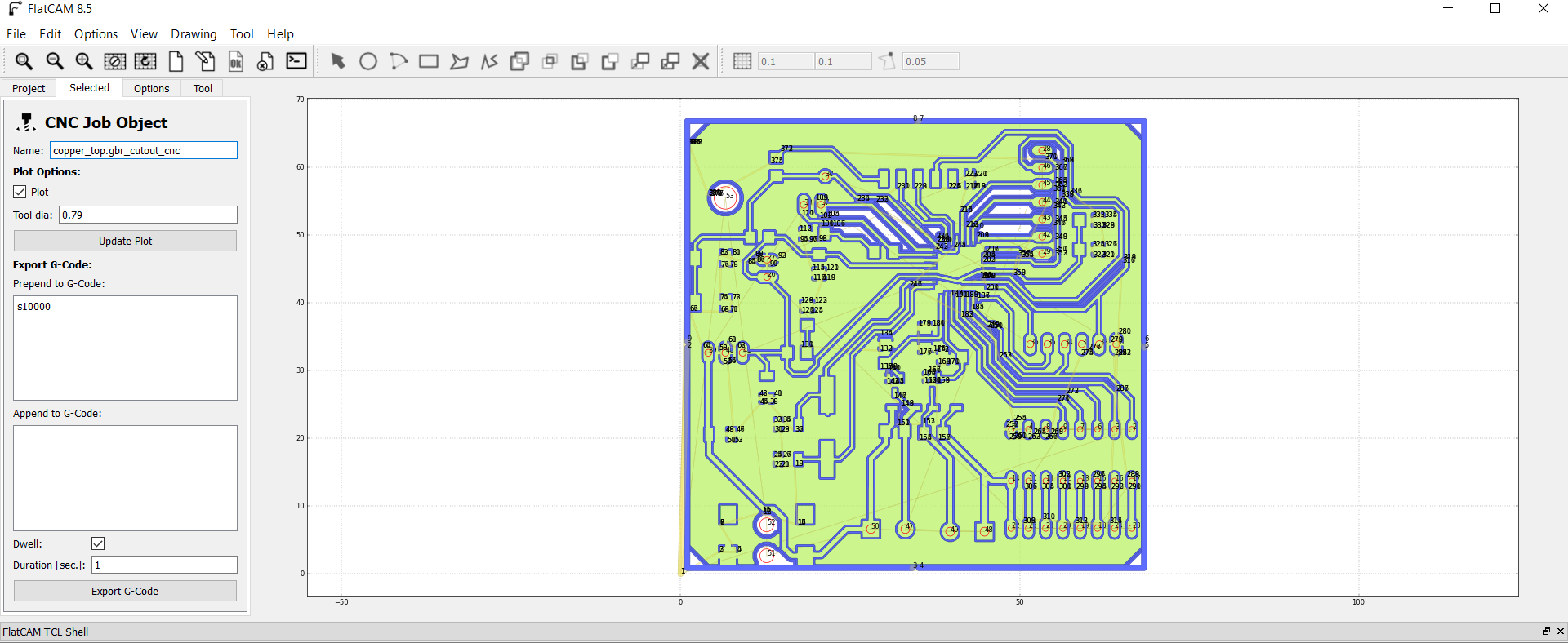
As shown in the above picture I got two jobs the first is for the inside and outside cut and the second one is for the drilling so I selected the cupper-top.gbr and then I went from project menu to select menu which in I can select the cutting variables, here I select the tool diameter of 0.2mm and the number of passes of 1 and the overlap is zero then I pressed generate geometry after this you can see the generated path for the inside cut and I did the same for board cut out and I generated the geometry as shown
Now after I finished cupper-top I went to project menu and I selected drill.xln
Here I put the cutting variables as shown
Now after I generated the insde, outside and drills files I got the CNC files so I opend each file.
In order to set the spendle speed I type s5000 in the exported G code this is mean the RPM is 5000 and its the maximum spindle speed in tormach PCNC 1100 and then I exported the G code as .nc
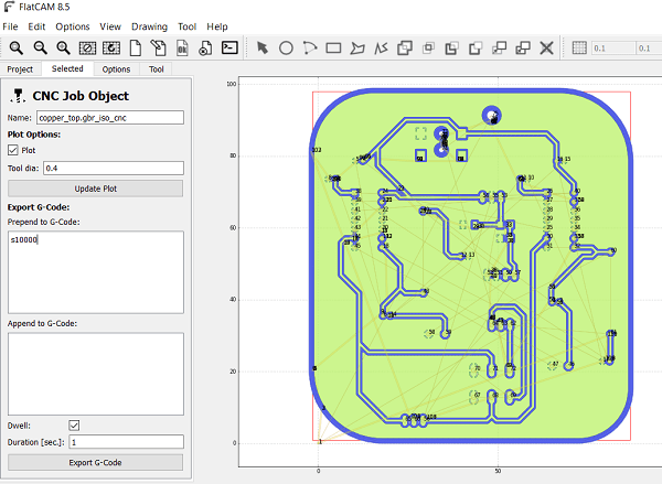
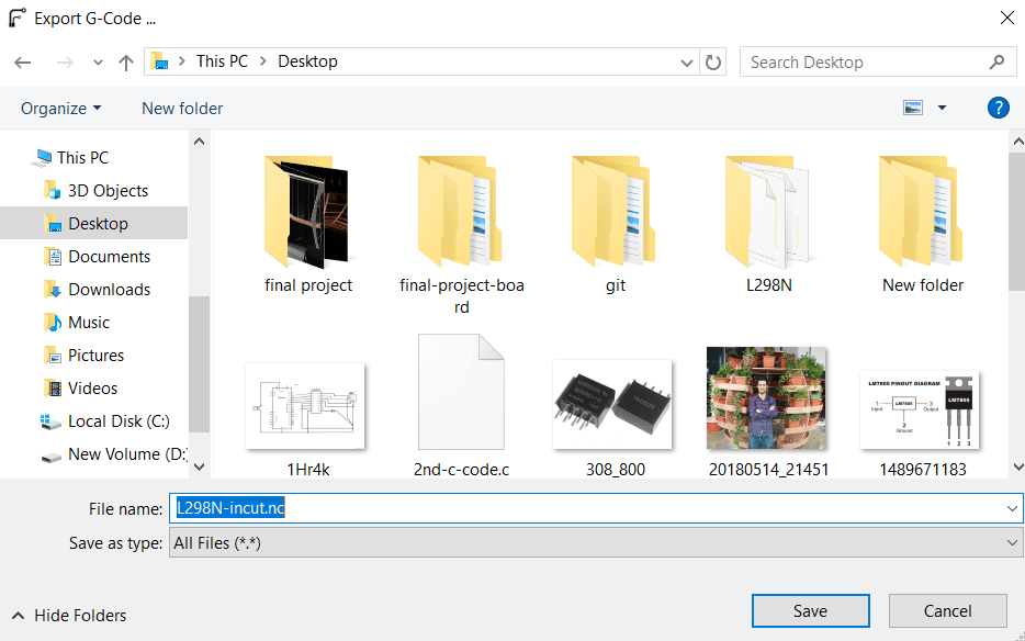
I repeated the process for the out and drill cnc files.
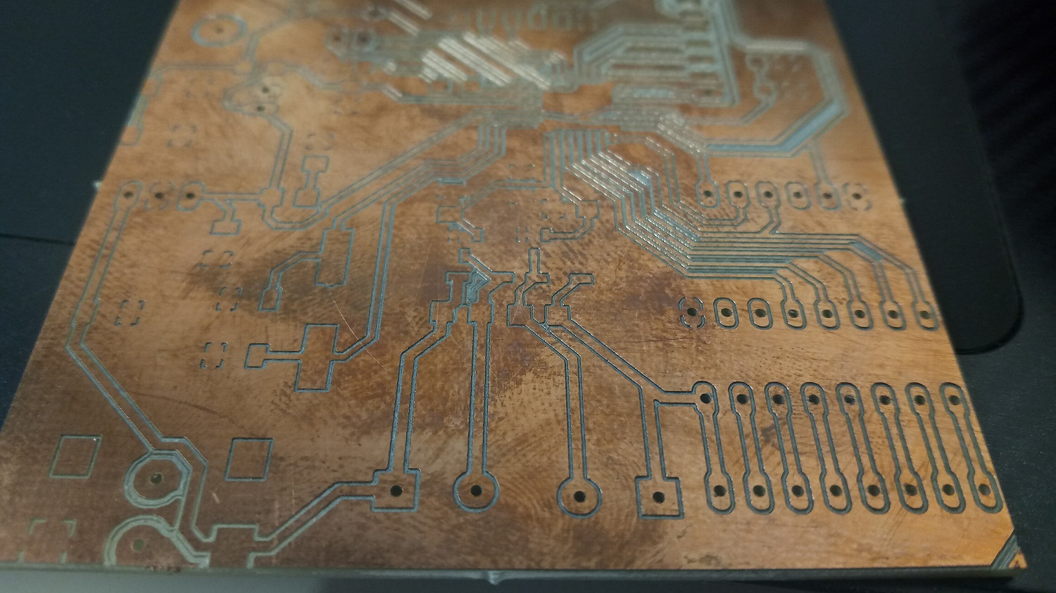
And this is my board after milling!
Now I start soldering
Look how much beautiful it is :D
And this is the components that I used :
1.Two capacitors 470uf 50v instade of 500uf because its the only avaliable
2.Two capacitors 5uf
3.Four capacitors 0.1uf
4.Tow resistors 2.7ohm
5.Tow LM384N
6.LED
7.One capacitor smd 10uf
8.One resistor 499 smd
9.Voltage regulator 5V
10.Power jack 5mm
Also, I need a DC to DC isolating converter, but unfortunately I didn't find it so what I did is to connect the Bluetooth module by another 5v power source
Now here is my 6w 8ohm AMPLIFIER board playing music :D
2.Motion System
In order to make a motion to my system I need to consider the wires friction so I need A driver motor with high torque, I knew that the stepper motors have a high torque so in my project I am going to use a stepper motor.
In our fablab we have two types of stepper motors and they are:
1.Four Wires 5VDC 1A Bipolar Stepper Motor
and the motor features are:
Rated voltage: 5VDC
Step angle: 1.8° ±5%
Phase resistance: 5Ω
Current: 1000mA
Detent torque: 150 g-cm
Holding torque: 1800g-cm
Mounting hole space: 1.22"
Mounting holes: 0.10"
Shaft diameter: 0.20"
Shaft length: 0.91"
Motor diameter: 1.54"
Motor depth: 1.34"
Weight: 0.44 lbs.
Screw Mount Dimensions: M3
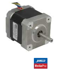
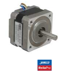
2.Six Wires Unipolar Stepper Motor 12VDC 0.4A
and the motor features are:
Four phase stepper motor
Rating: 12V @ 0.4A per phase
Step angle: 1.8 ± 5%
Detent Torque: 250 g-cm
Holding Torque: 3.2 kg-cm
Inductance per phase: 28 ± 20% mH
Resistance per phase: 30 ± 10% Ω
Speed: 100-600 RPM range
Mounting hole space: 1.22"
Mounting holes: 0.10"
Shaft diameter: 0.20"
Shaft length: 0.95"
Motor diameter: 1.67"
Motor depth: 1.89"
Weight: 0.60 lbs.
Screw Mount Dimensions: M3
I chose the second one unipolar stepper to use it in my project because it has higher holding torque than the bipoler one on why I used the stepper instead of the DC motor because I can control the speed of it just by the code so I will have the specific RPM that I want .
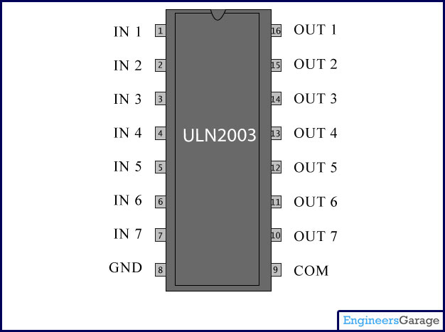
In order to controll the stepper motor I want to use ULN3003AN which is an array of seven NPN Darlington transistors and here is the features of it :
• 500-mA-Rated Collector Current (Single Output)
• High-Voltage Outputs: 50 V
• Output Clamp Diodes
• Inputs Compatible With Various Types of Logic
• Relay-Driver Applications
I designed a board with atmega 328p, I added a 5mm power jack and the voltage power is 12 volts and it's connected with the ULN2003AN to feed the stepper motor, also I have added a voltage regulator 5v to feed the board, here is the eagle schematics of the board :
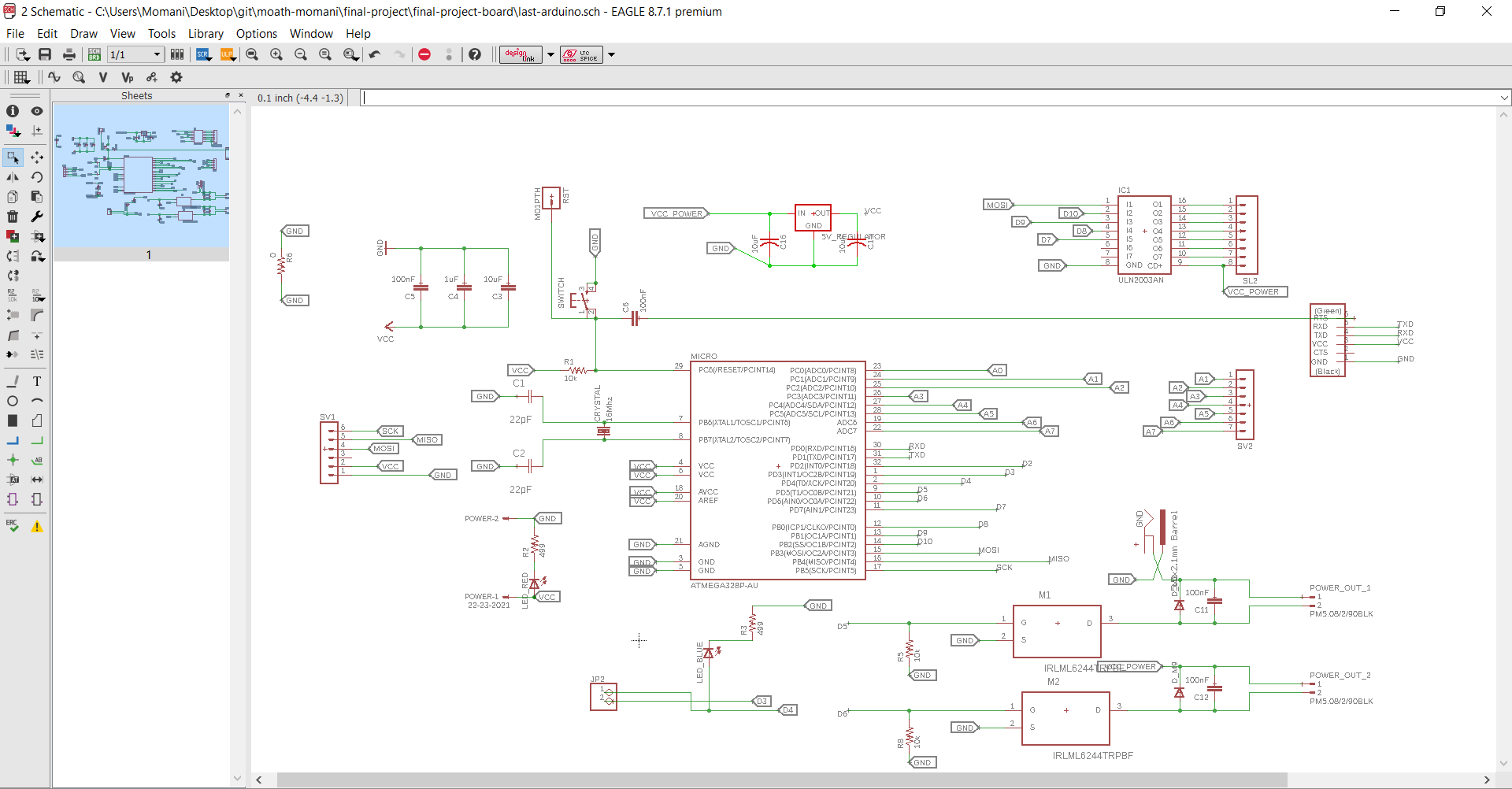
Also in this schematic I have designec a voltage regulator circuit outputs 5 volts to feed the microcontroller(atmega 328p)
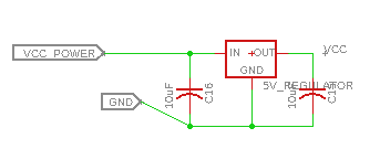
The output power of the power sorce is 12v 2A so the voltage regulator takes 12v and output 5 volts
In my project I have 2 fans 12v and RGB strips 12v also the stepper motor nema 17 12v so I have designed two terminals 3.5mm, two pos and the output the same input 12 volts, also you can see I designed two power MOSFET IRLML6244TRPbF connected with pin 5 and 6 in the IC so I can turn the terminals off and on by the code and what happen when I write in the code digitalWrite(5, HIGH); digitalWrite(6,HIGH), the mosfet will connect with the ground and the 12v is already connected so the terminals will output 12 volts
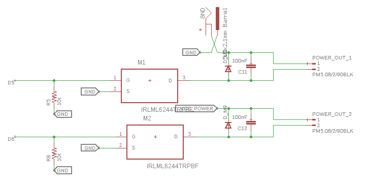
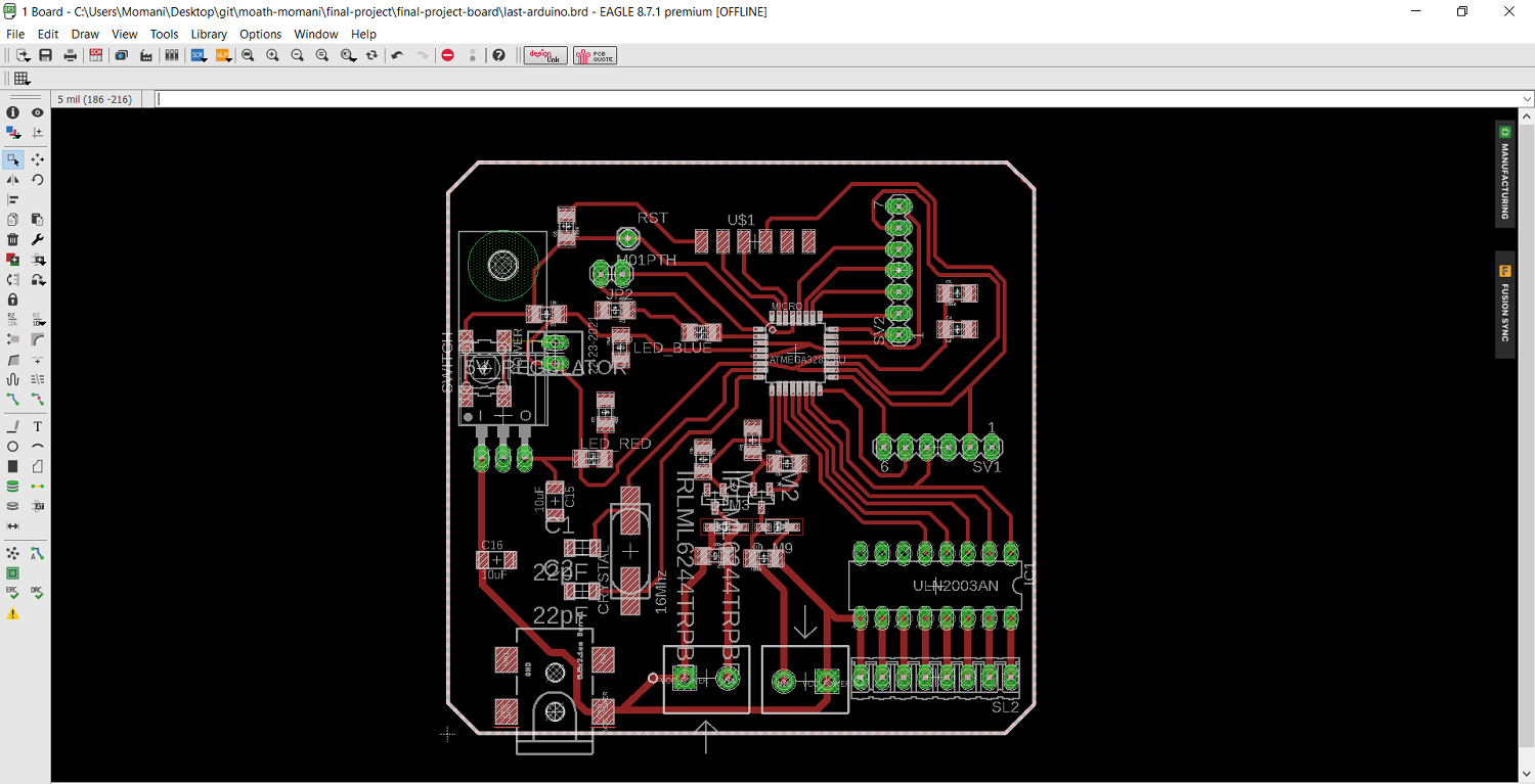
And this is the board lyout:
Pin out
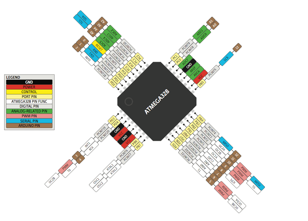
Download Board Schematics and Layout
After I finished designing the board I have generated the cam files.
Now I will use FlatCAM again as the same previous procedure for the amplifier board to mill my board by using Roland SRM20.
For the traces I used 0.2mm V shape endmill with cutting feed of 240mm/m
For the outside cut and holes I used 0.79mm flat endmill with cutting feed of 30mm/min
After I got the generated cnc files I exported the nc files
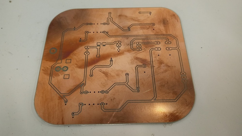
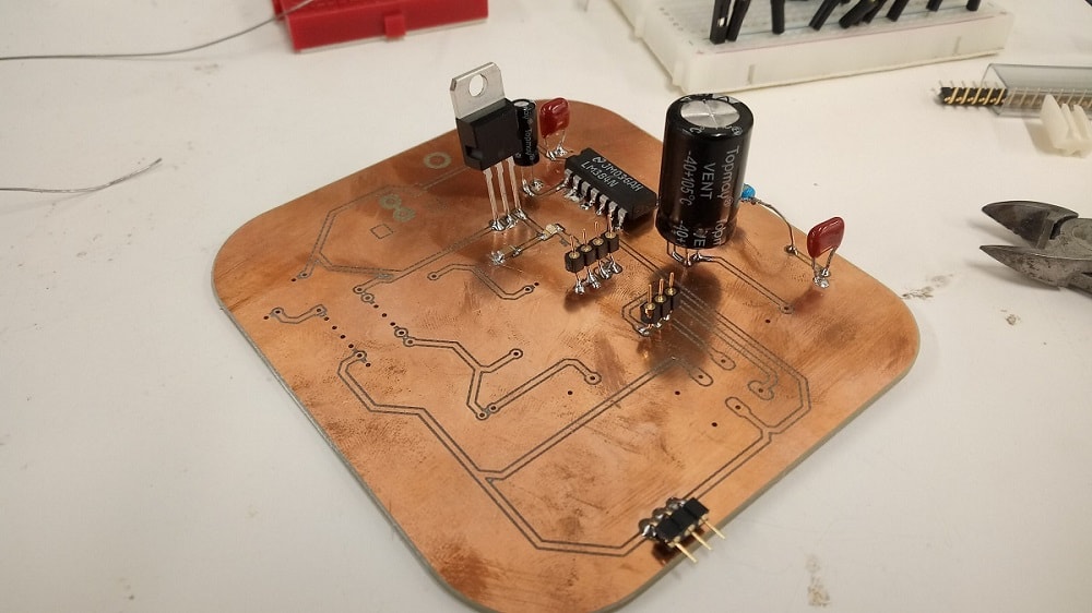
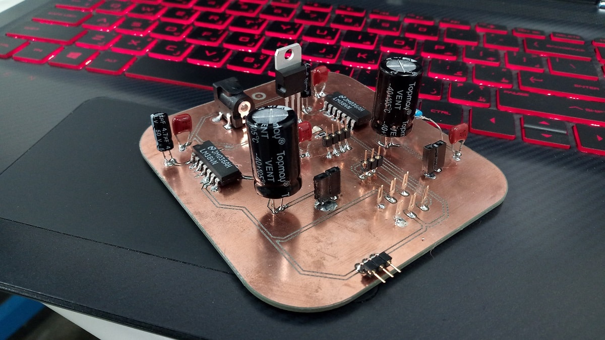
Here is my board after milling
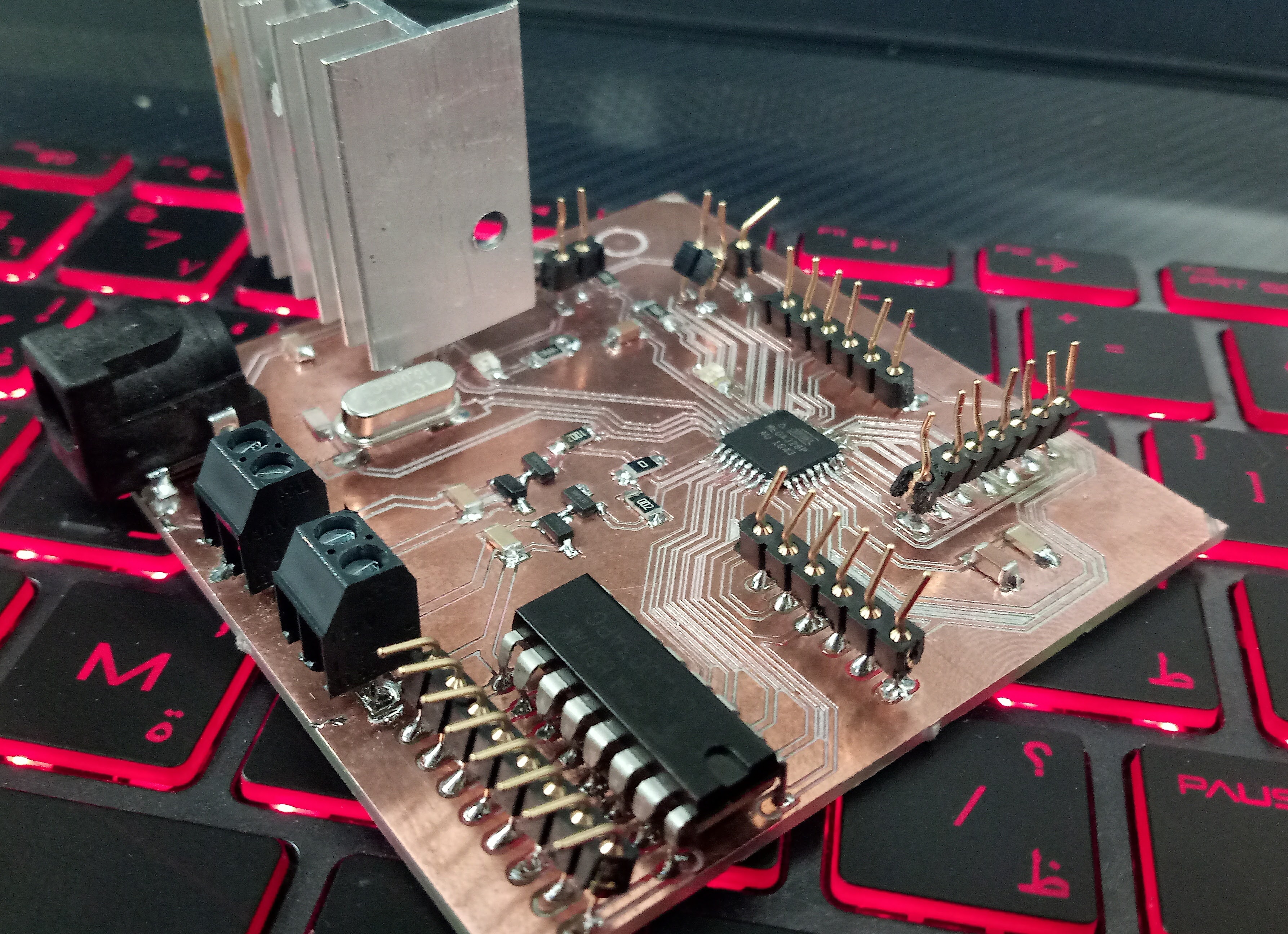
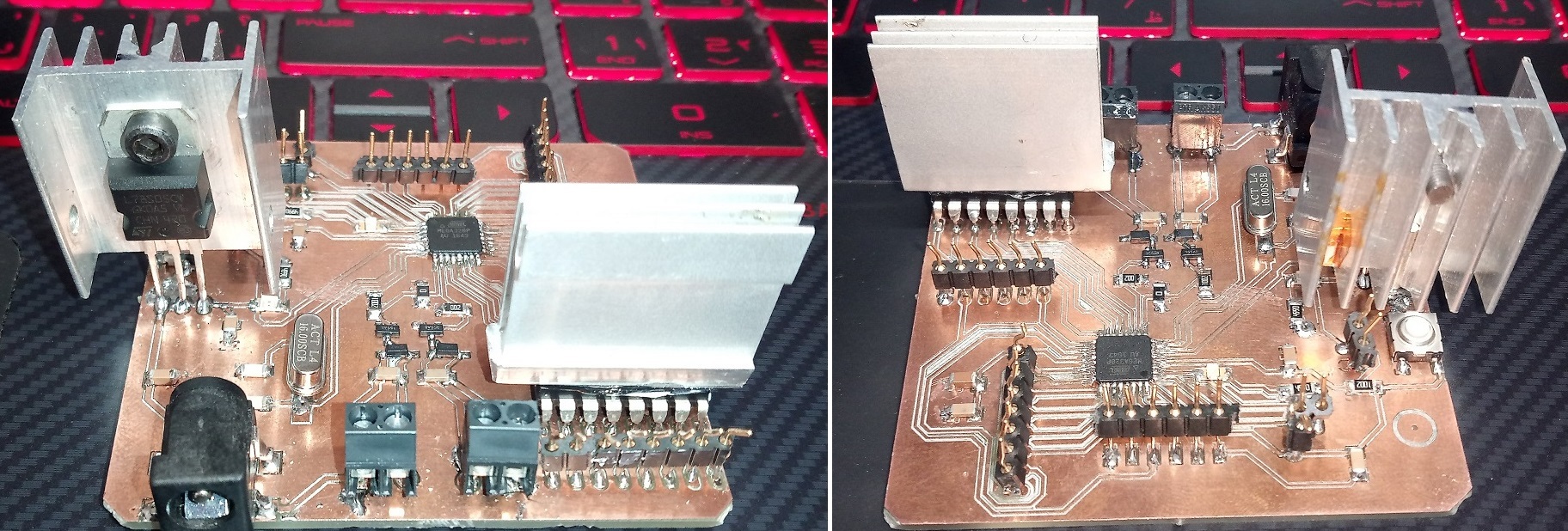
The components of my board are:
1. ATmega 328p
2.ULN2003AN
3.Power jack 5mm
4.Crystal 16MHz
5.Tow capacitors 22pf
6.Four capacitors 100uf
7.Three capacitors 10uf
8.One capacitor 1uf
9.Two LEDs
10.Two resistors 499 ohm
11.Three resistors 10K ohm
12.Voltage regulator 5V
13.Two power MOSFET IRLML6244TRPbF
14.Two diods
15.Two terminals 3.5mm, two pos
16.RST button
17.Pin headers After I got my board its time to give it a life, so I went to Arduino IDE and I uploaded the Arduino as ISP to the arduino
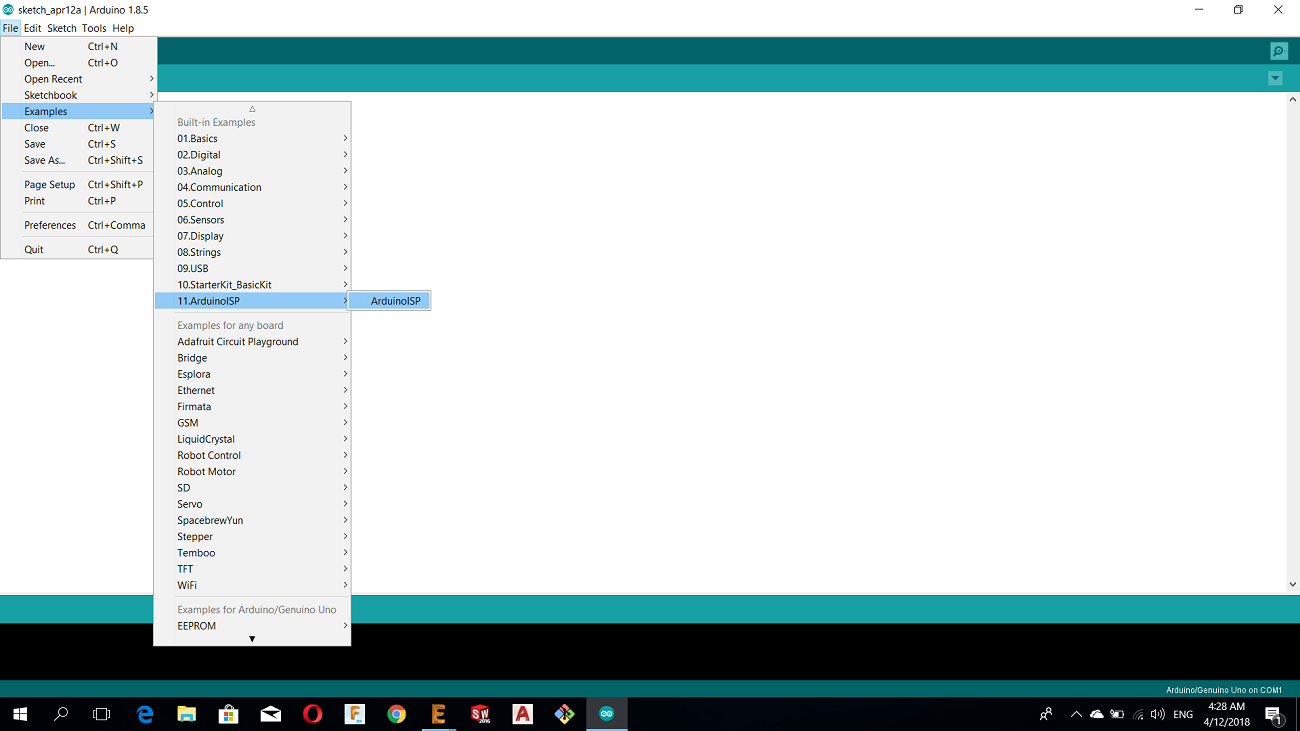
The second step is to connect the the arduino as ISP with my atmega board to upload the code by the following connections:
SCLK: Serial Clock ------------------------> Arduino Pin 13
MISO: Master Input Slave Output ------> Arduino Pin 12
MOSI: Master Output Slave Input ------> Arduino Pin 11
RST: --------------------------------------------> Arduino Pin 10
VCC: Positive supply voltage -------------> Arduino VCC
GND: ---------------------------------------------> Arduino GND
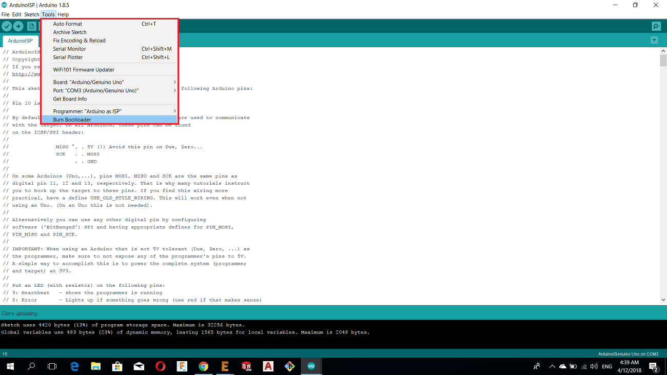
Then from tools I chose the following options and then BurnBootloader
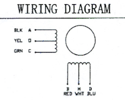
In order to controll the motor in unipolat mode I connected the centers wires which they are the white and yellow with the power source pin for ULN2003 which is com 9
And then I connected the phases wires RED, BLUE, BLACK, AND GREEN with OUT COM 12, 13, 14 and 15 respectivly
After I uploaded the following code using FTDI cable
#include <Stepper.h>

const int stepsPerRevolution = 200;


Stepper myStepper(stepsPerRevolution, 7, 8, 9, 10);
#define led 2
void setup() {

  // set the speed at 20 rpm:
  myStepper.setSpeed(20);

  Serial.begin(9600);
}

void loop() {
  // step one revolution  in one direction:
  Serial.println("clockwise");
  myStepper.step(stepsPerRevolution);
  digitalWrite(led,HIGH);


}
Here is a video for the stepper motor Nema17 controlled by the board.
Download the stepper Code
For more details about the stepper motor and programming you can visit this Link
Until now I have achieved the main part in electronics so what is next is ...
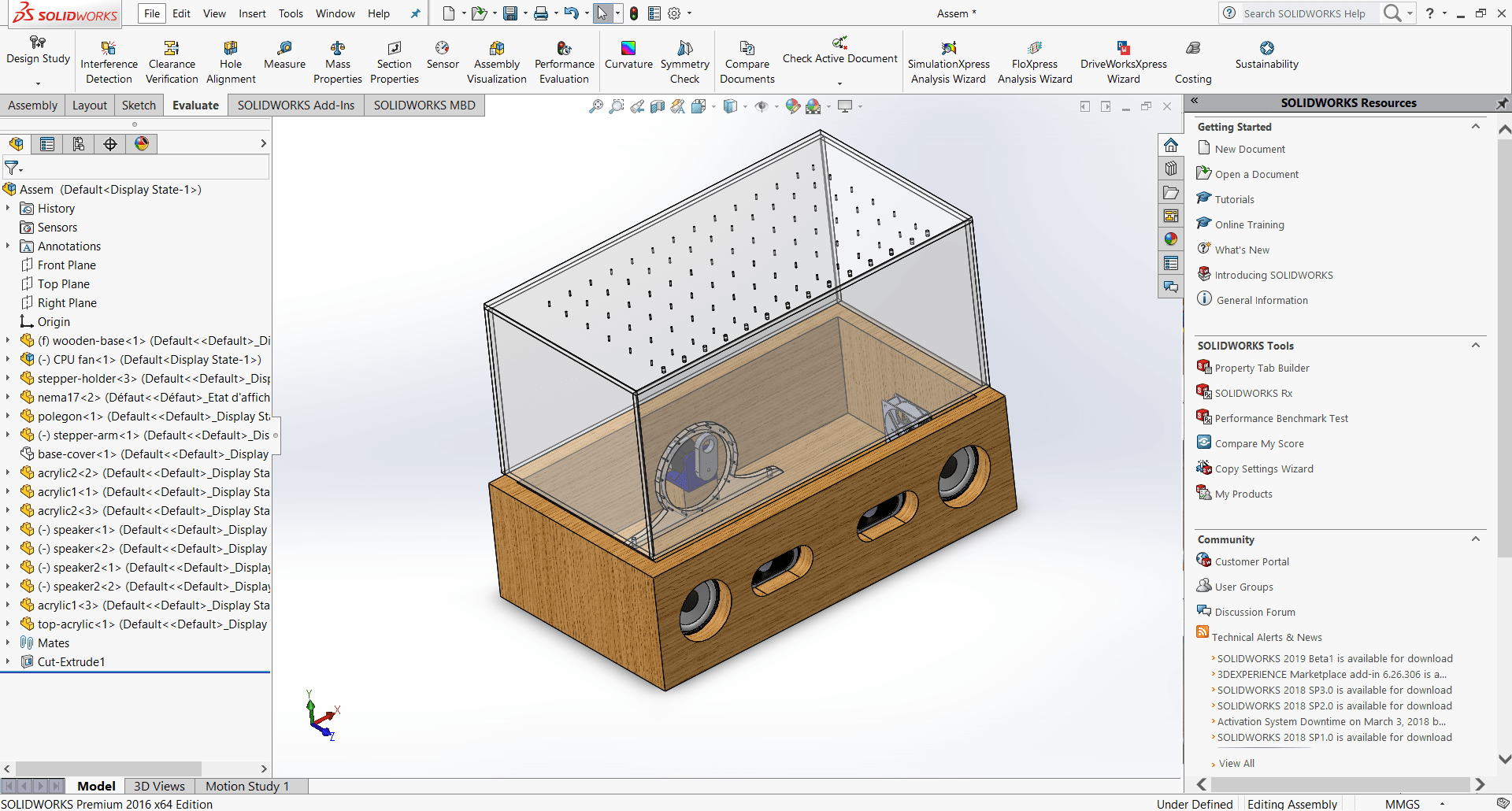
3.Computer Aided Design
There is many parametric cad softwares that I can use like fusion 360, inventor and solid works but my fav software is solidworks so I'm going to design my project using this software
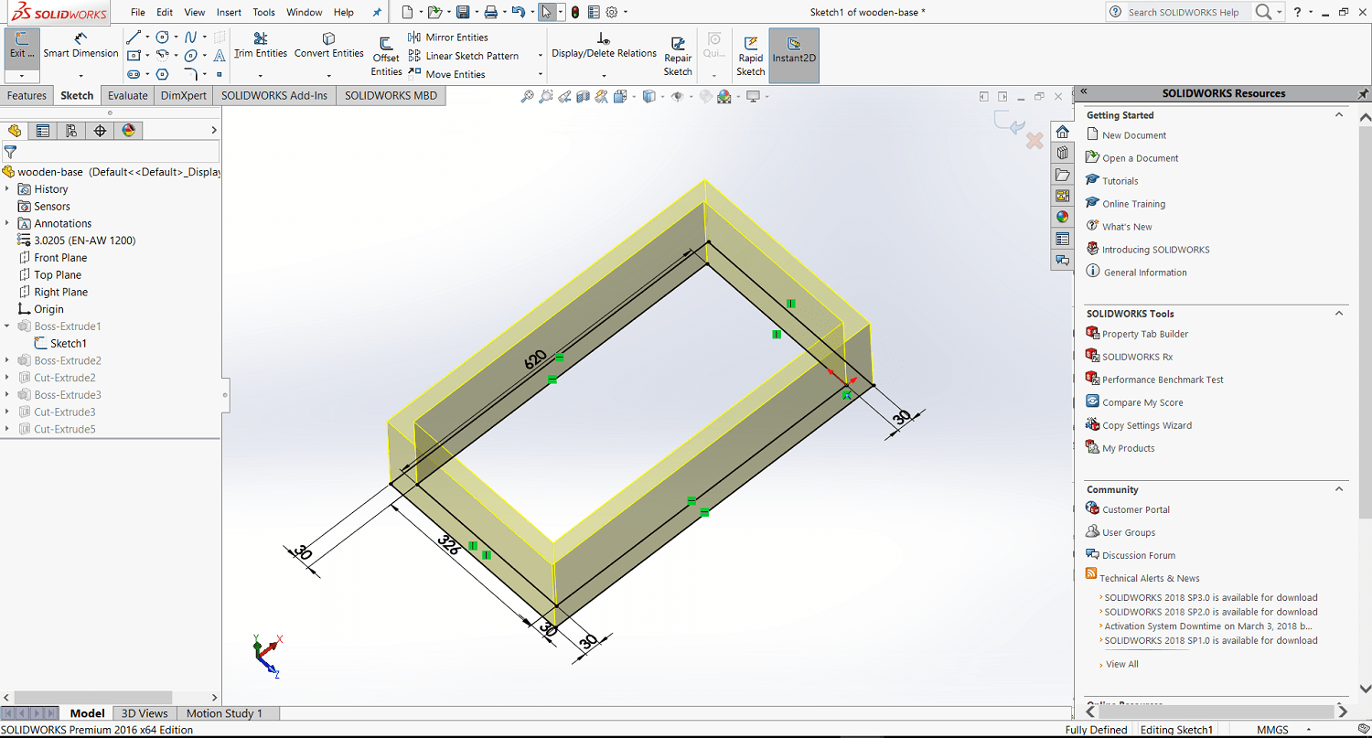
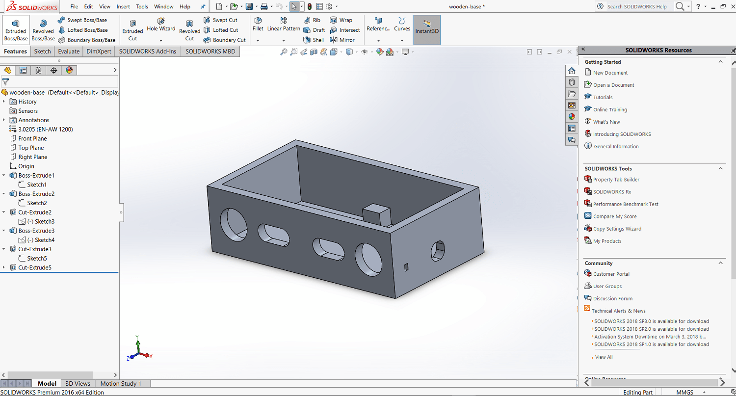
I started the design with the BASE so I have made a sketch and then extrude to make it a 3D model then I added some changes on it, and here is the sketch
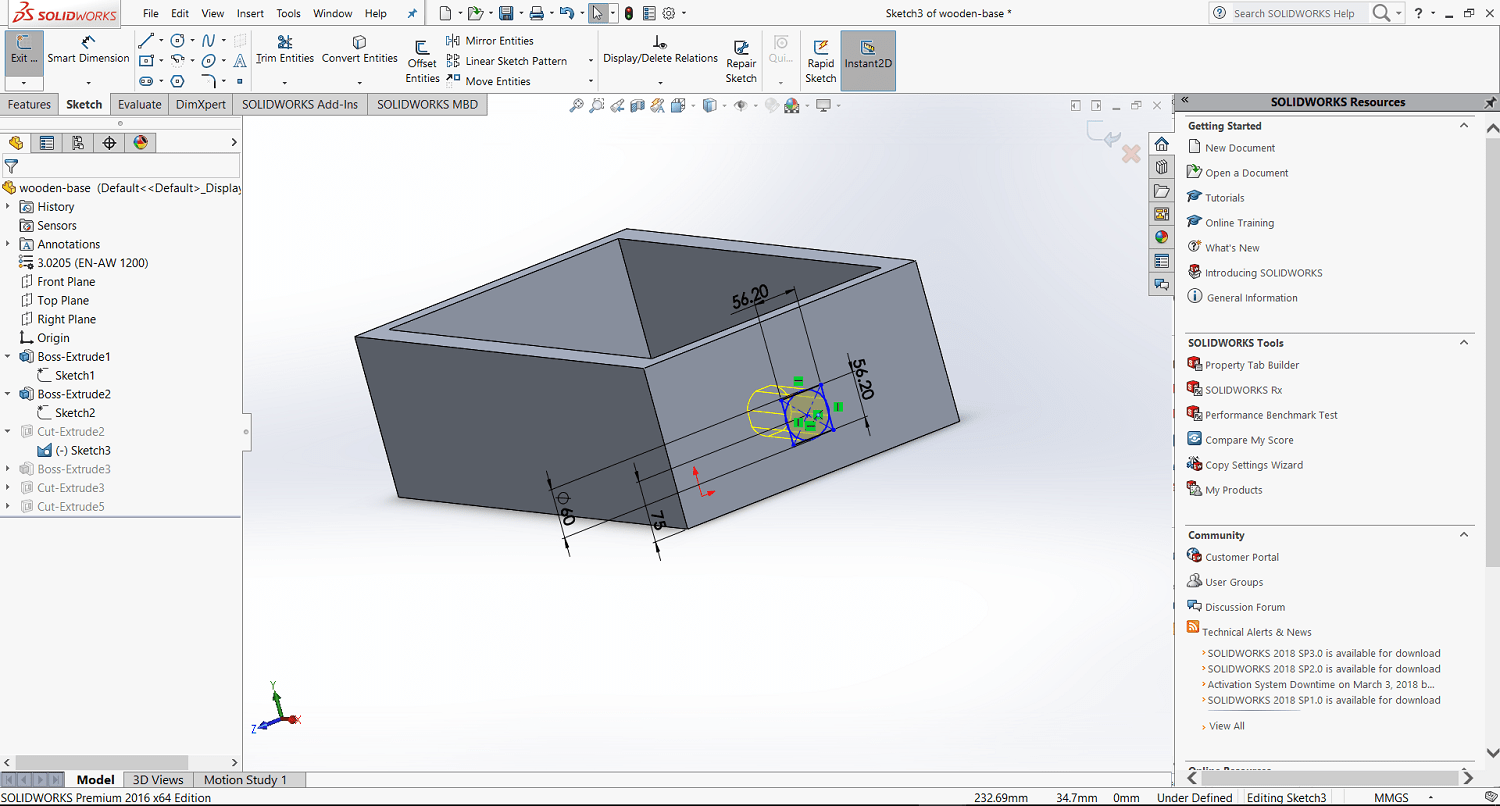
Here I made a stand for the stepper motor
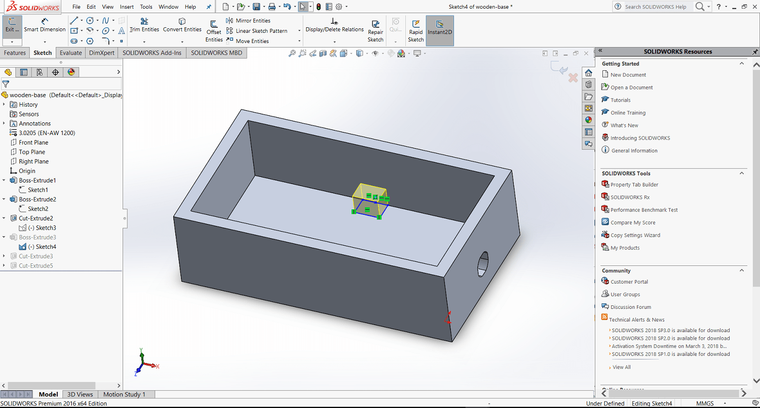
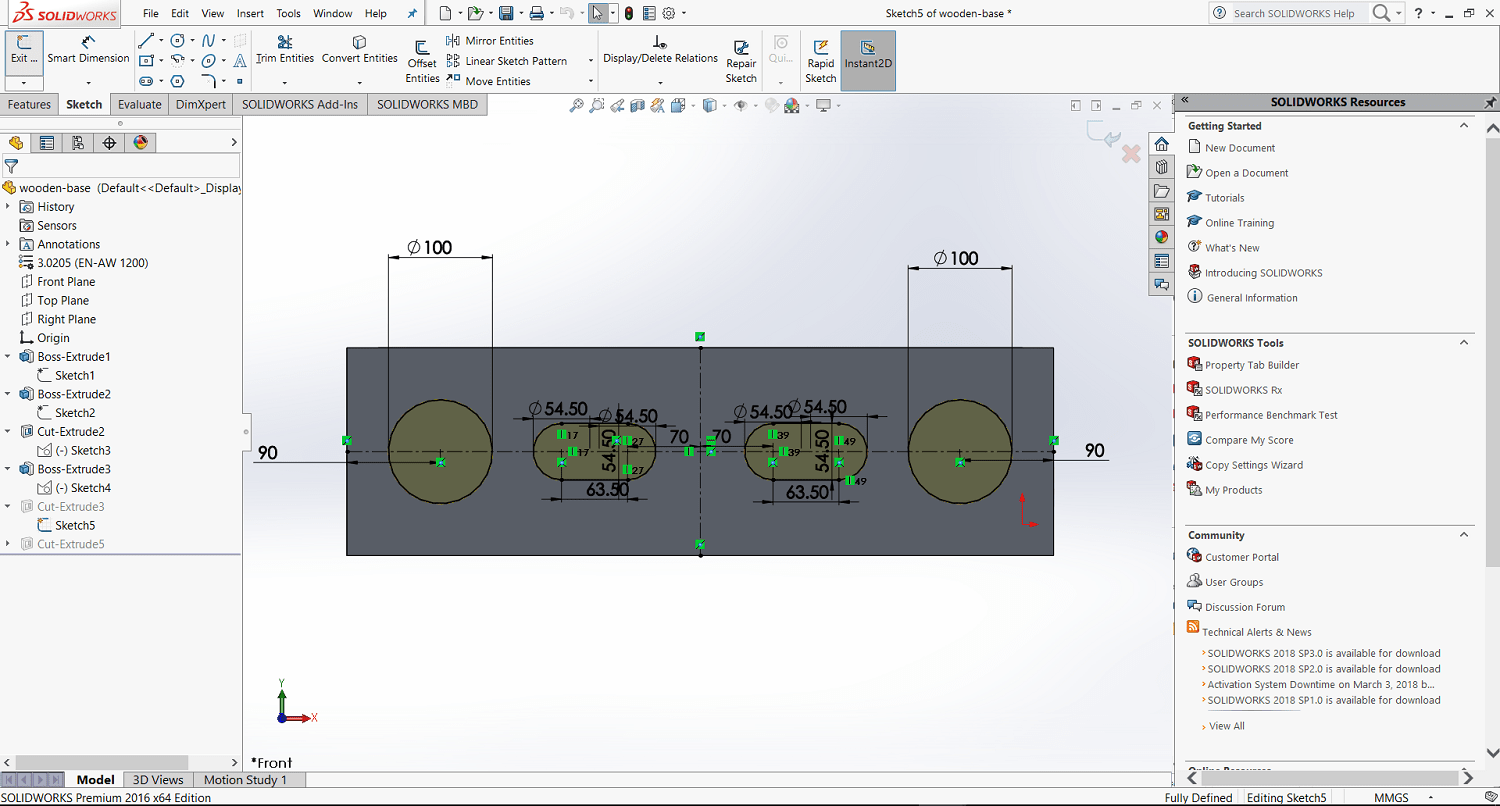
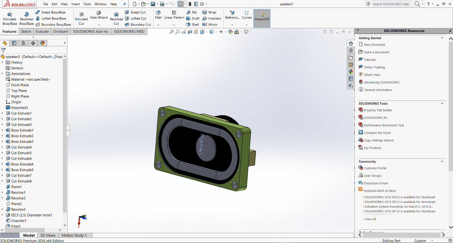
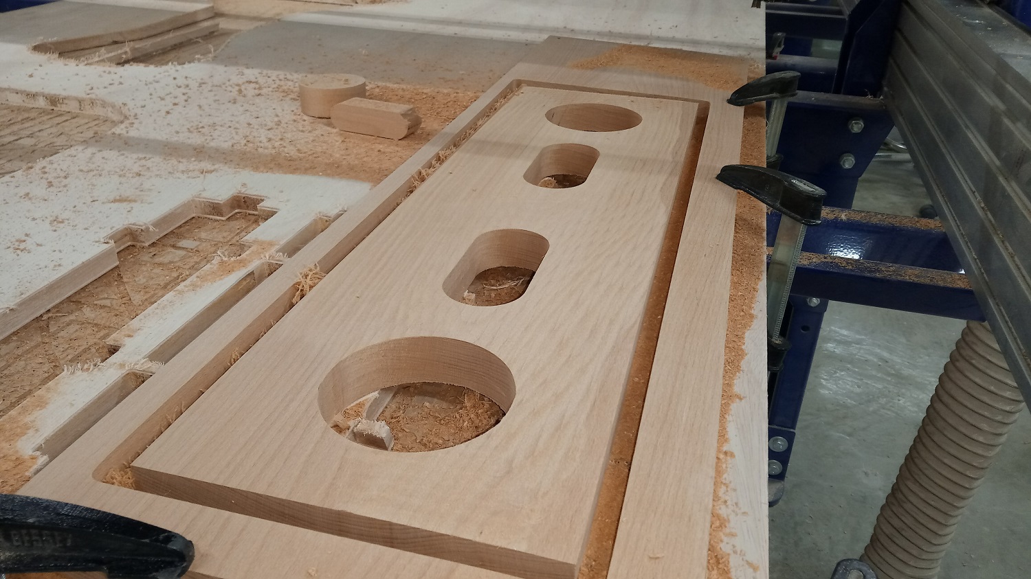
Because I want to add a sound system in my project I need to make a pockets for the speakers so I made extrude cut for the speakers
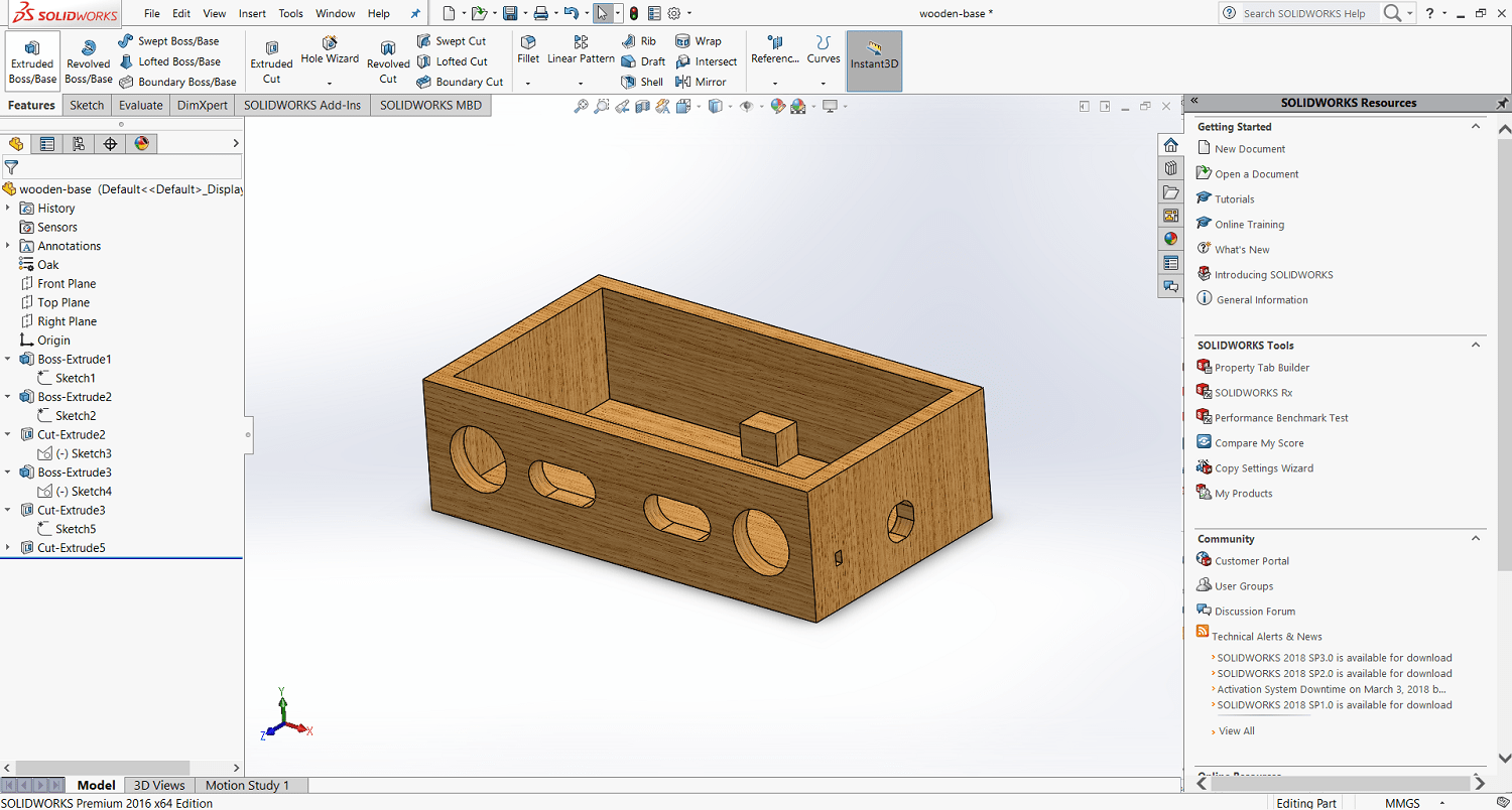
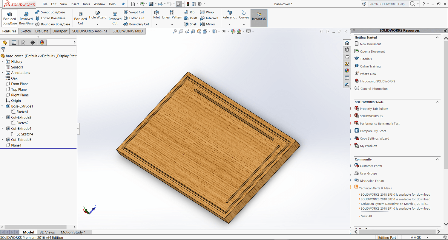
Here is the final base, but I will made the project from oake wood so I have changed the material to oake wood
After I started with the base cover and here is the sketch
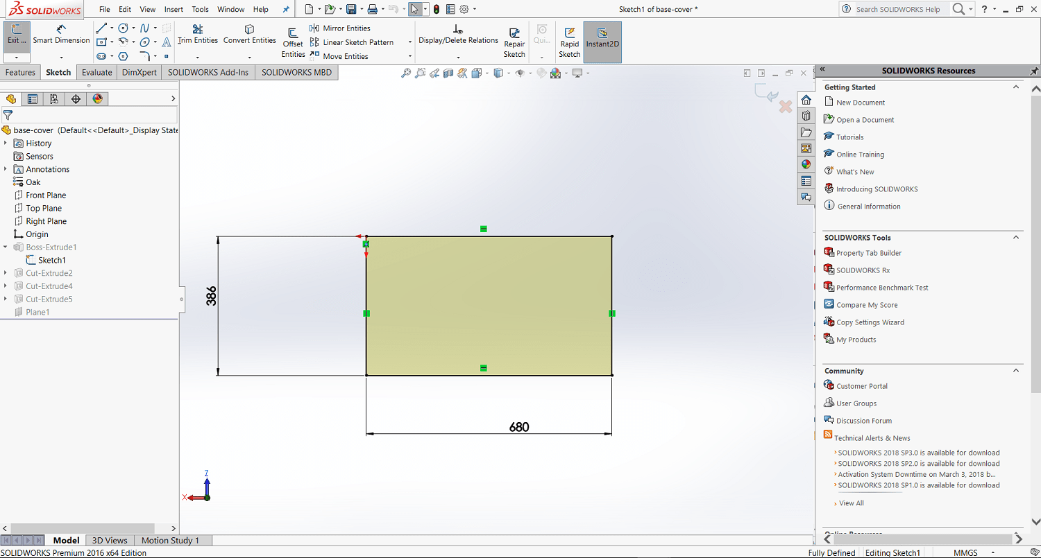
I made a slots because I want to make acrylic box
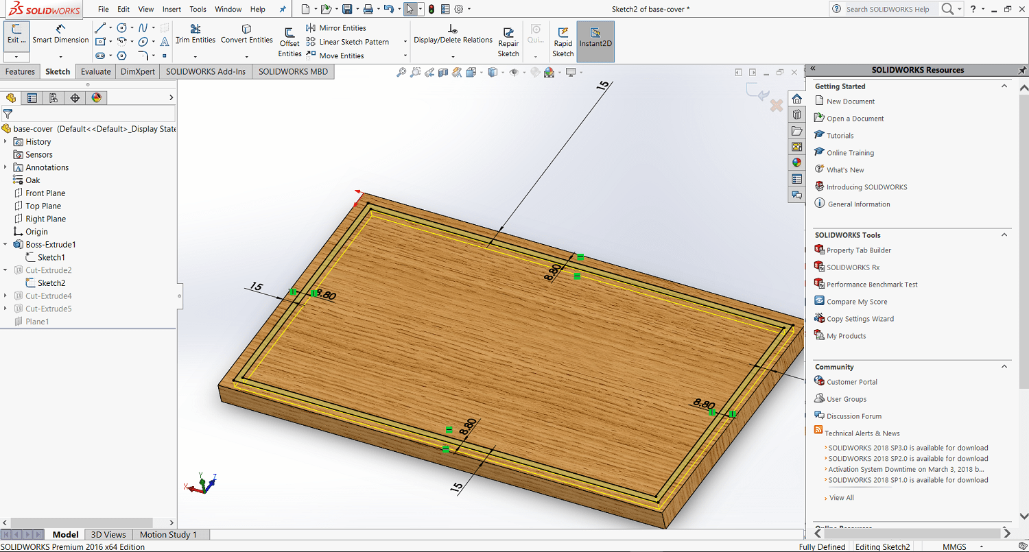
And this slots are for wires
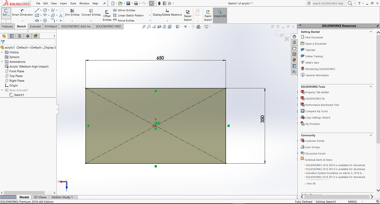
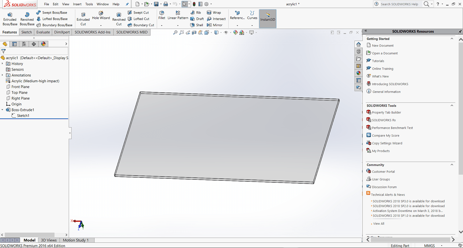
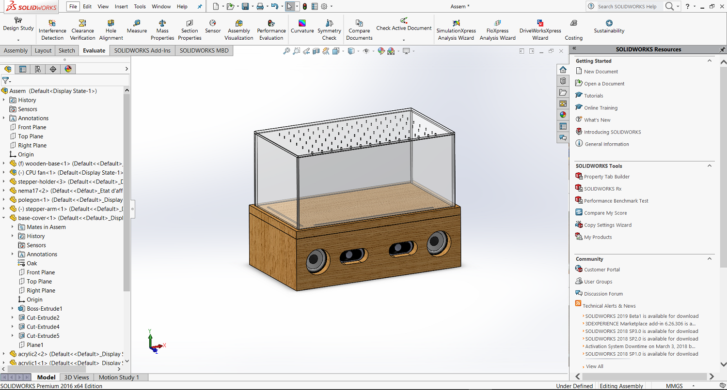
After I start with the acrylic and because I want the inside components are visible I chose the acrylic to be transparent
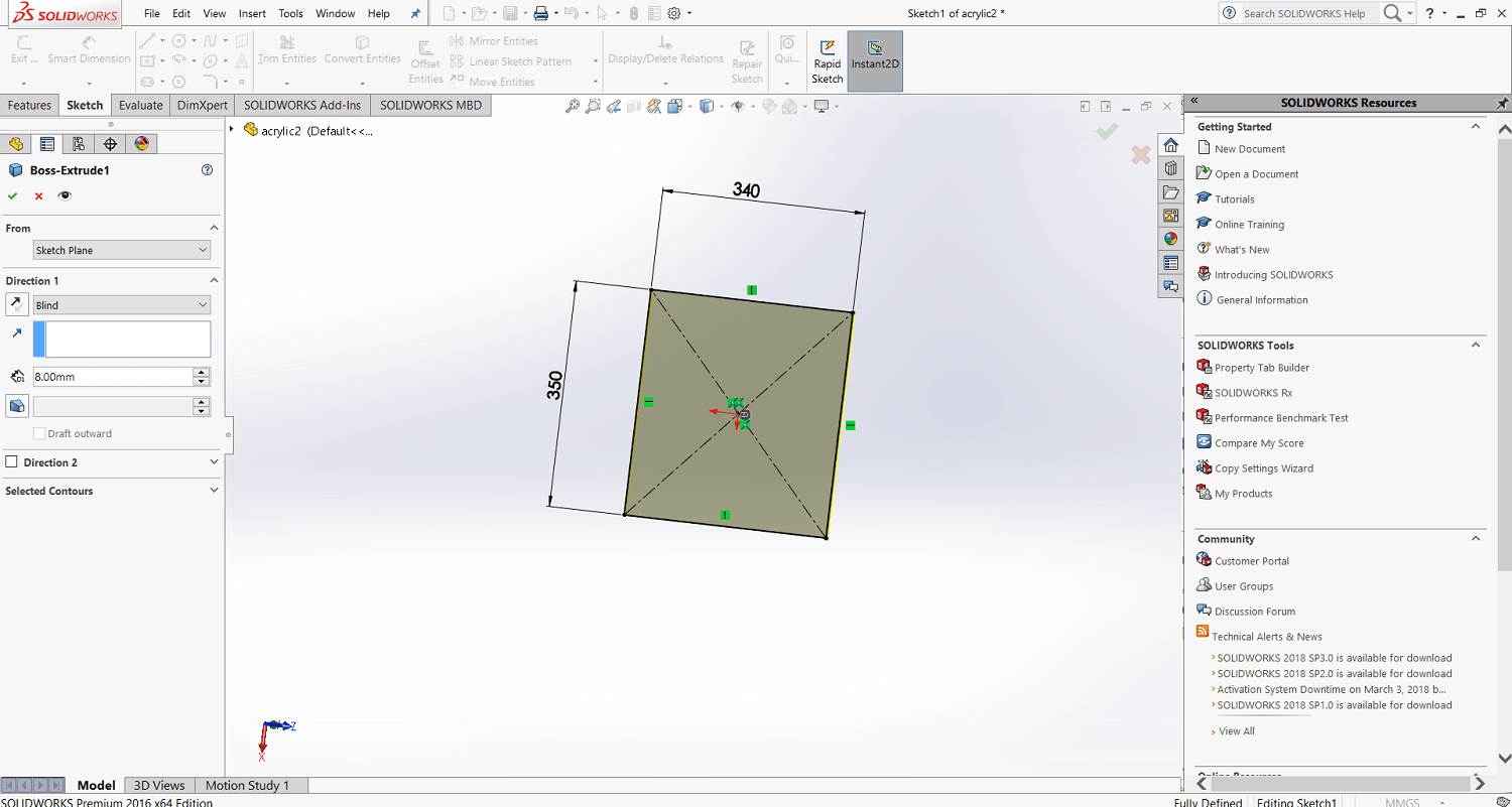
This is the second side of acrylic
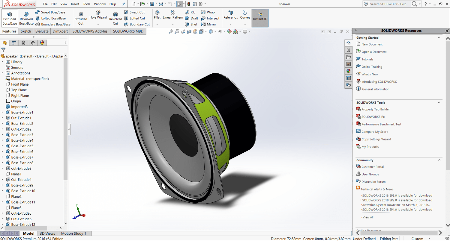
After I have Imported a speakers from grab cad and I edited them to be the same as my speakers
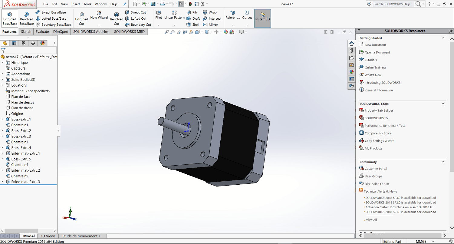
Also I imported a stepper motor Nema17
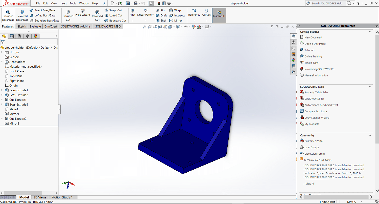
Then I designed a holder for it
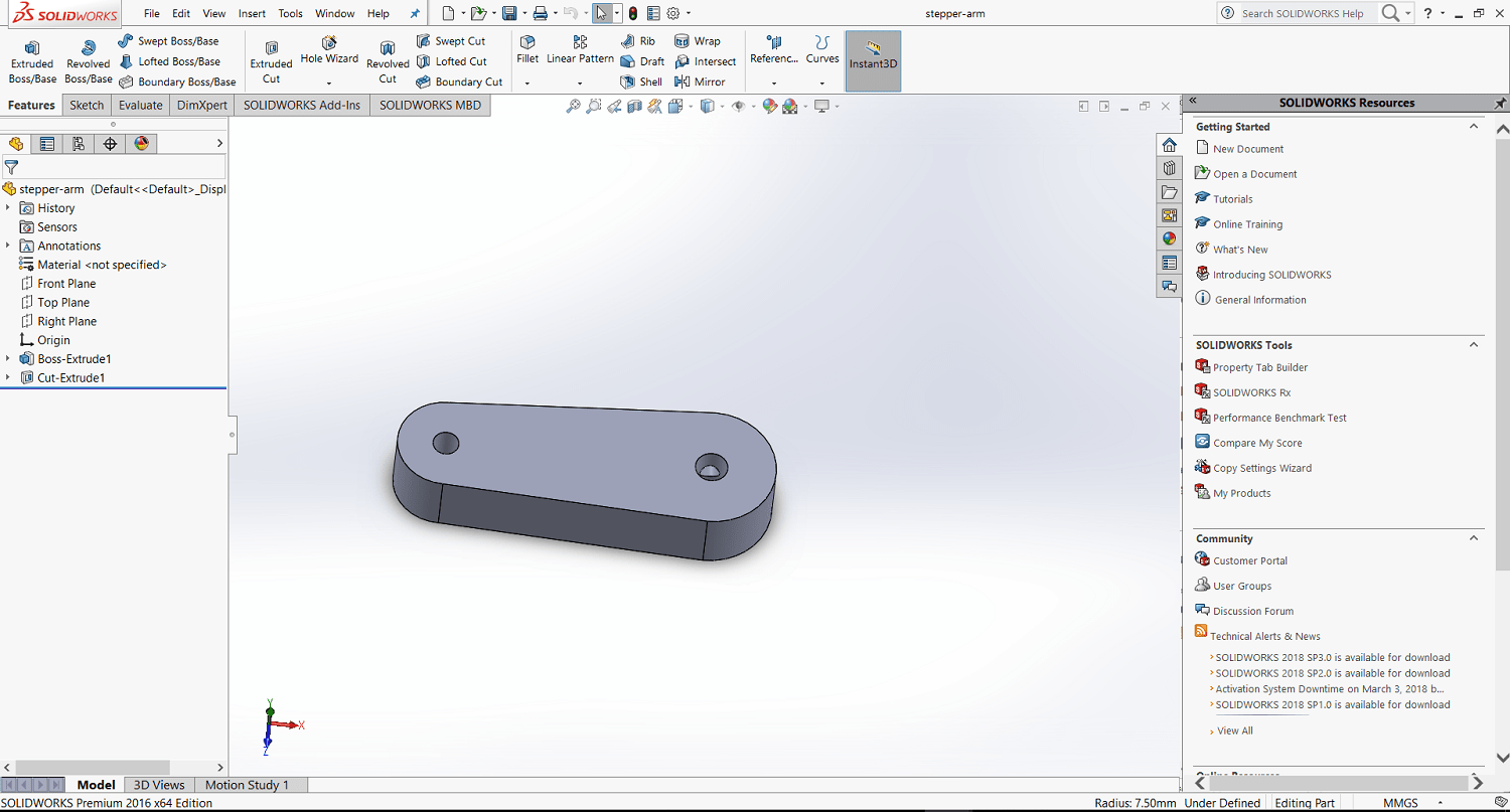
Then I designed the motors arm
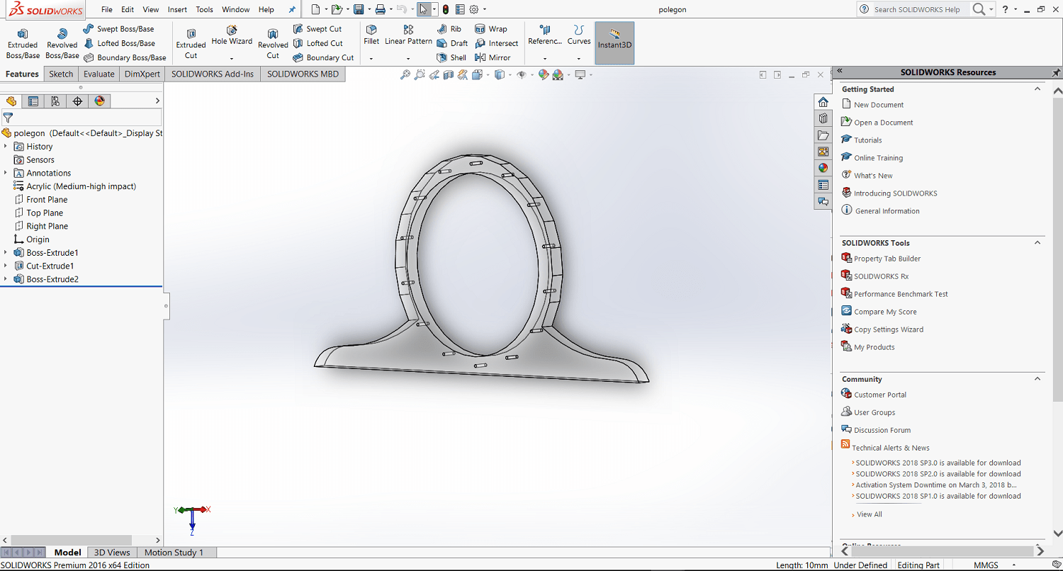
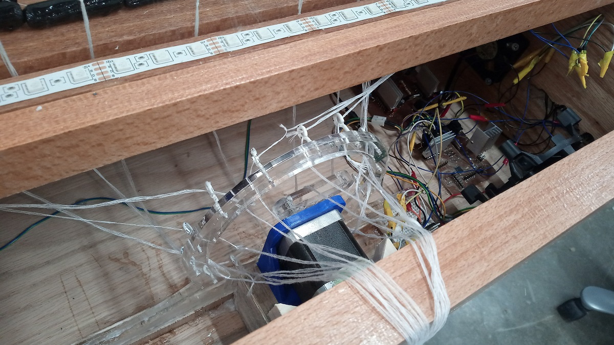
After, I designed a polygon shape, this part is very important because all the wires will connected through it and the motor will controll the motion of the system through it
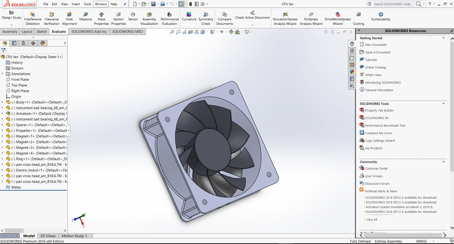
To avoid extra heat I have to make a cooling system so I have imported a fan
Now its the time to assembly so I did standard mates for the speakers
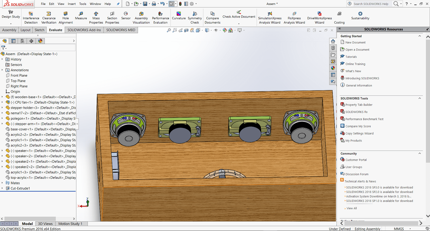 and here is the motor
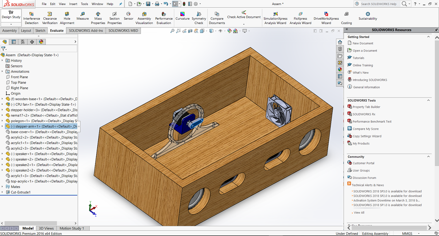
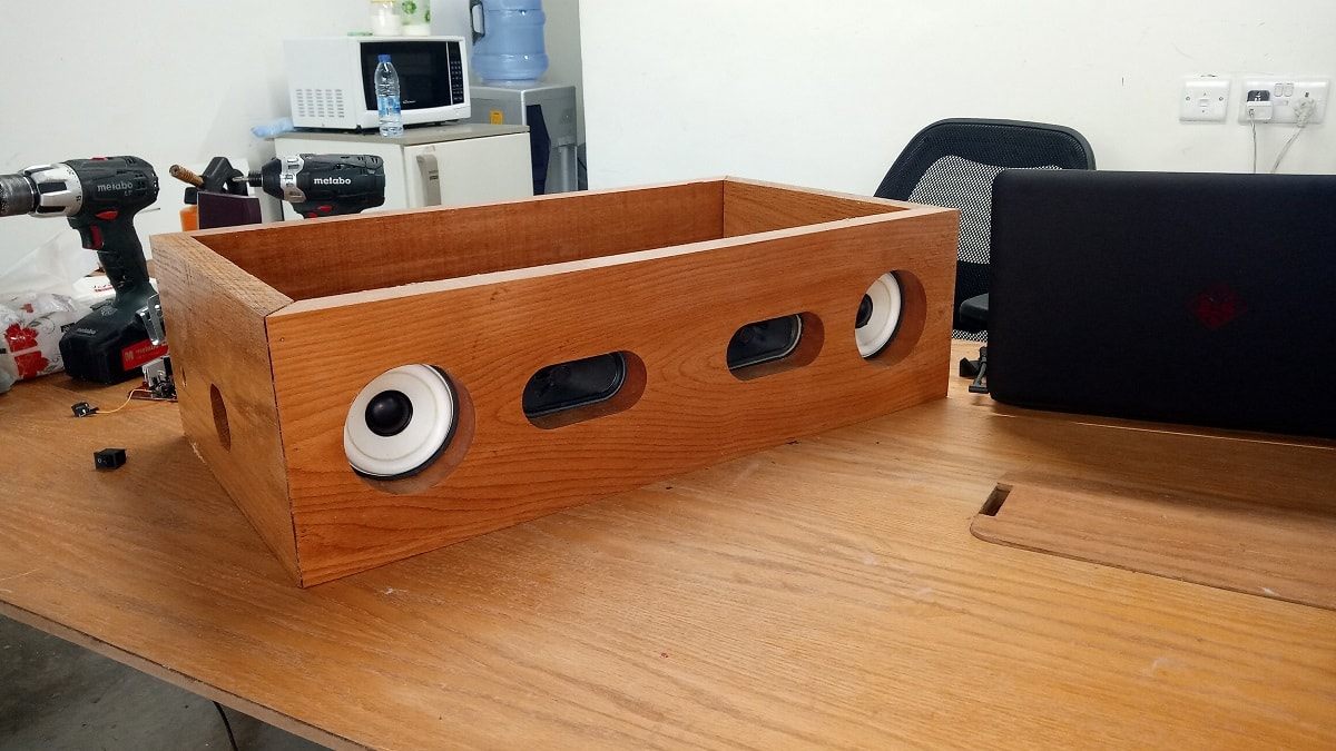
This is the final BOX
For more details about the CAD you can visit this Link
Download assymply sld
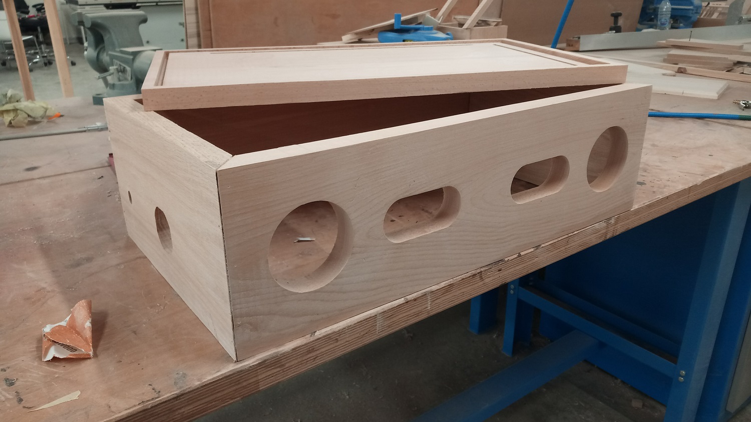
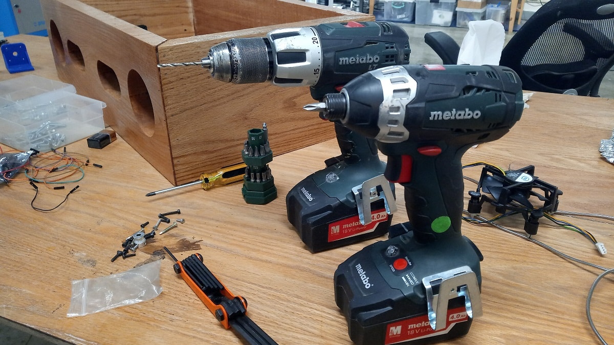
4.Computer Controll Machining
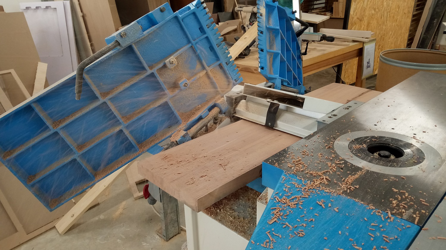
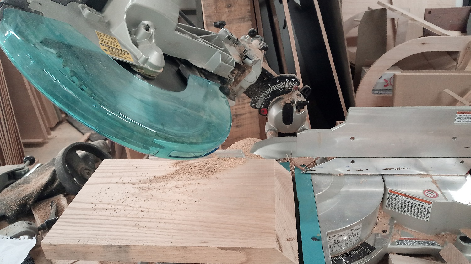
Before I start machining the wood I have to resize it and make it clean so I used manual machines for that, for example I used the compiner wood machine
Then I went to ShopBot machine but before I turned on the machine I have to prepare the cam file so I used V-carve pro to generate the tool path
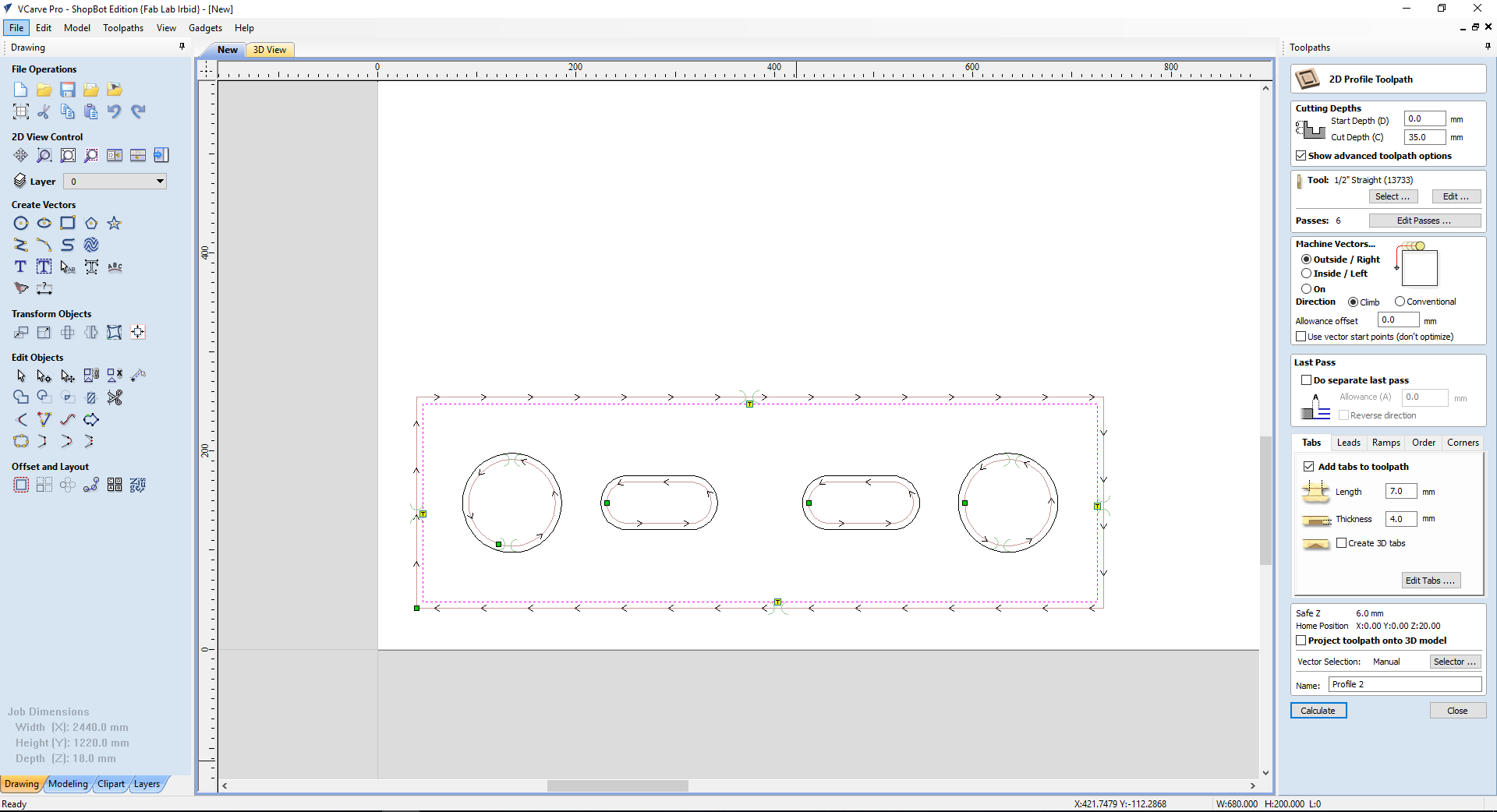
The oake wood considered as a hard wood so I used diffrent speed and feed for the 1/2" solid carbide endmill
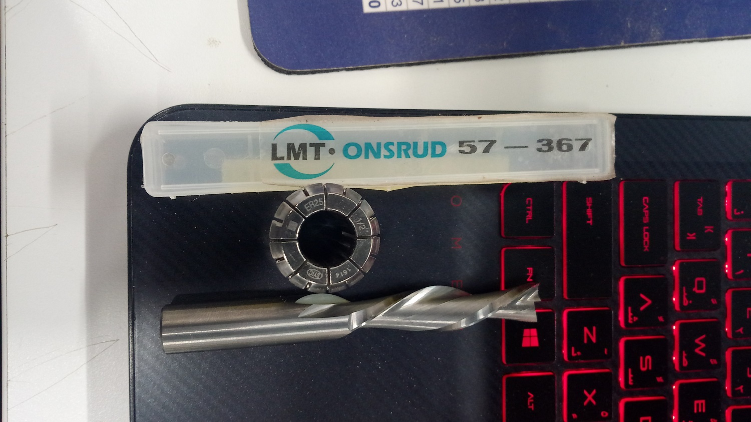
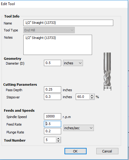
We can see in the picture I used 10000 RBM because the oak is a hard wood not a soft wood so I have to reduce the speeds also the feed is 2.5 inch/s and after I get a perfect finish
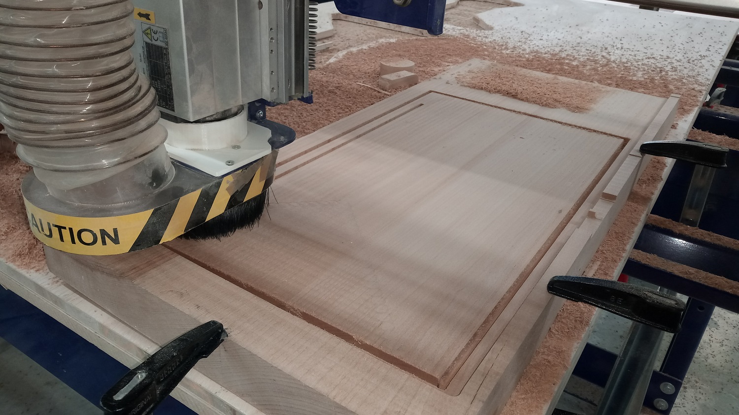
For these slots I used 1/4" flat end mill with RPM of 15000 and feed of 2 inch/s
After the machining I cut the edges by 45 degree
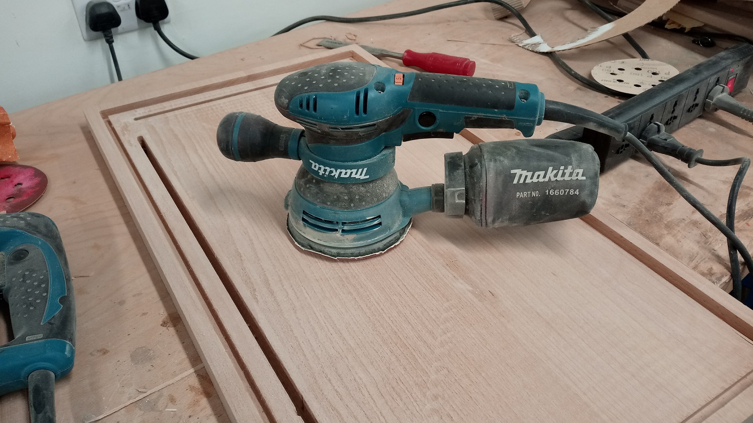
To achieve the best finish I used this manual vibrator
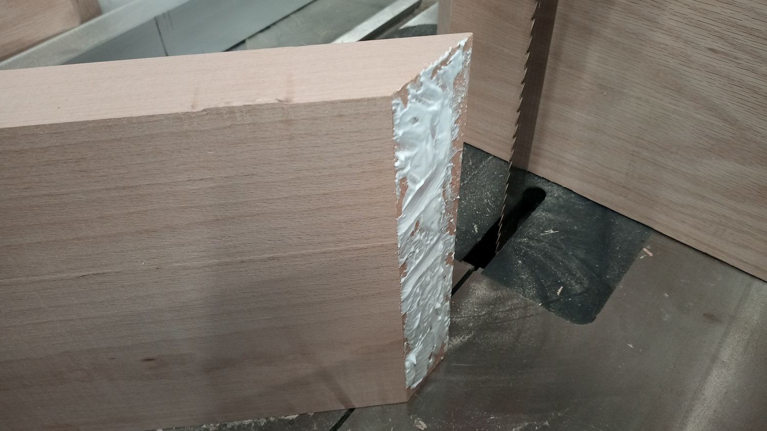
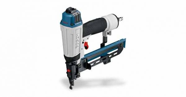
To join the corners I used the wood glue with a hydraulic nail gun
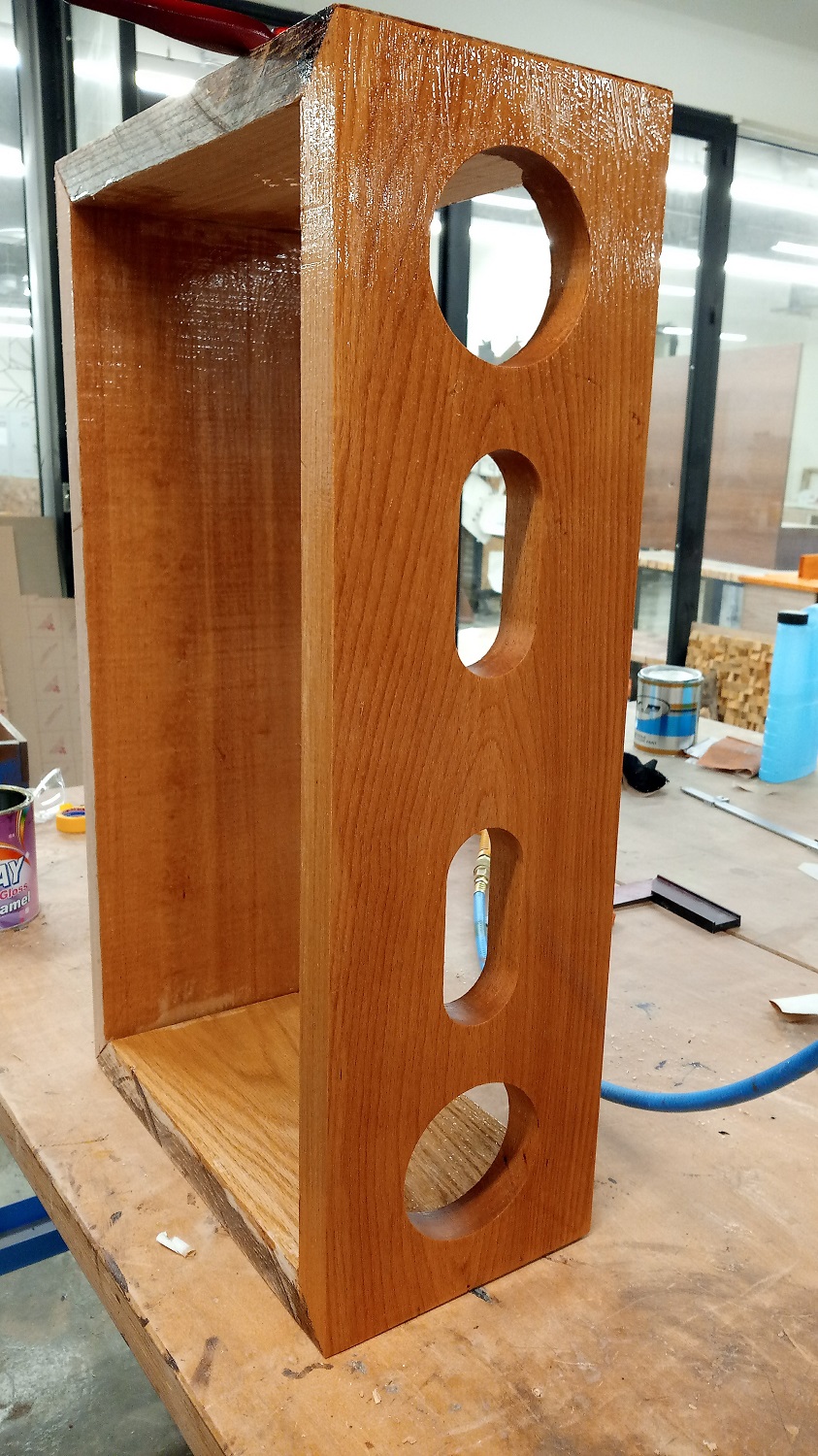
After I have finished the assembly I start painting the wood with varnish
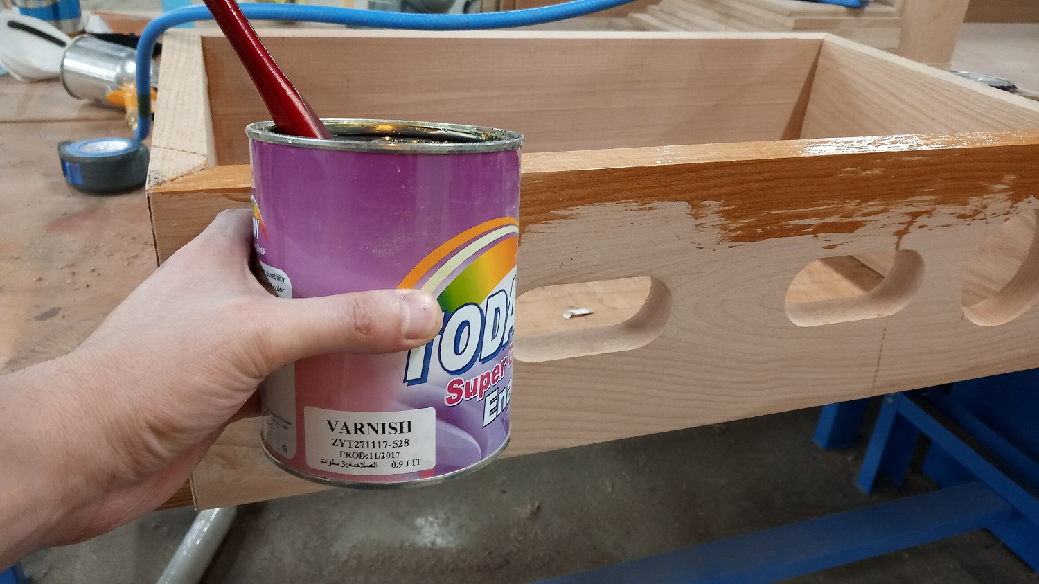
and look how much beautiful it has become

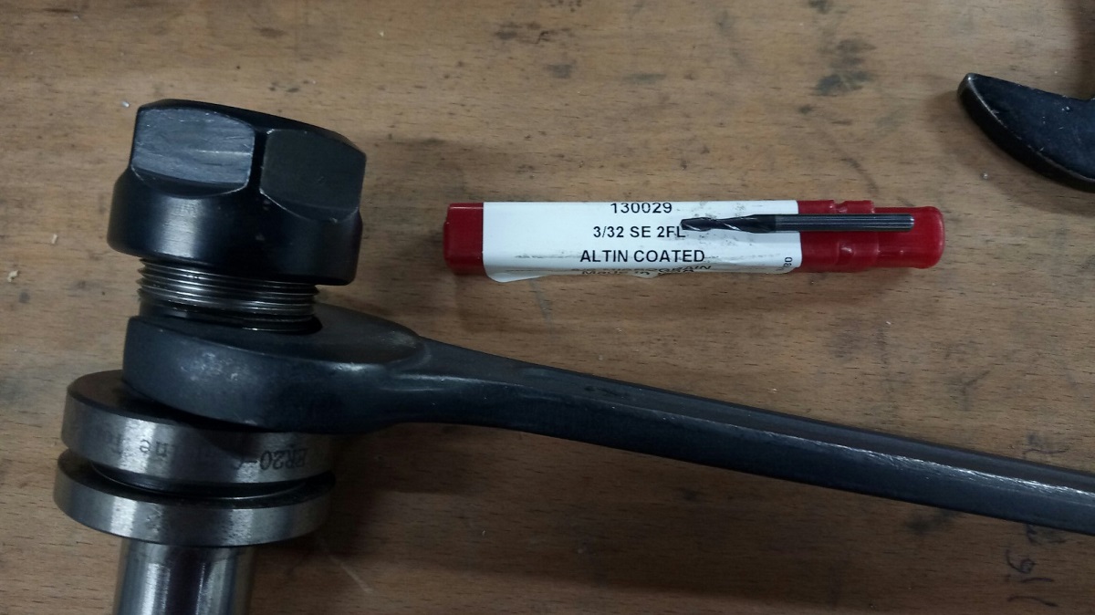
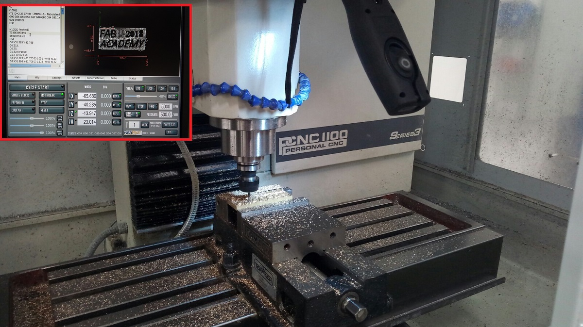
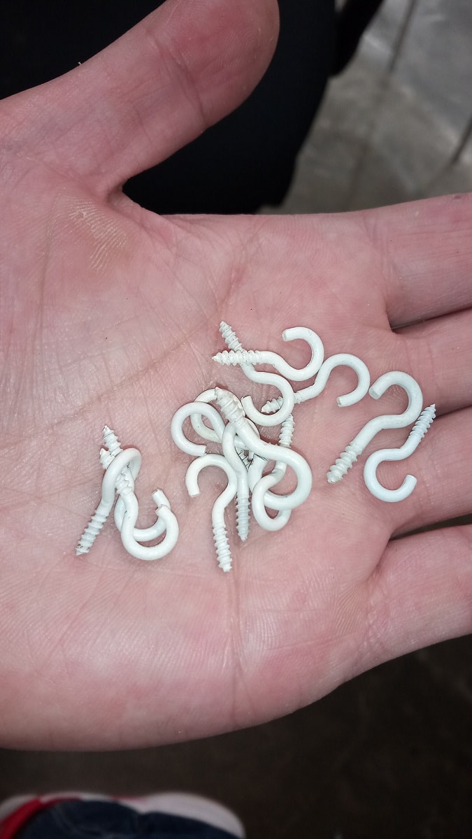
After I finished the box I made the sculpture chain by hand, first I drilled these pieces with Tormach pcnc 1100
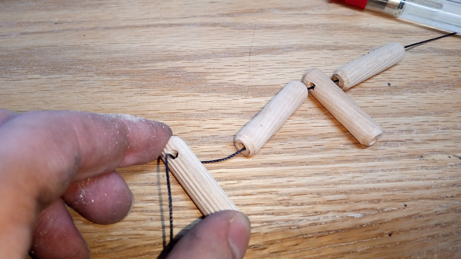
After
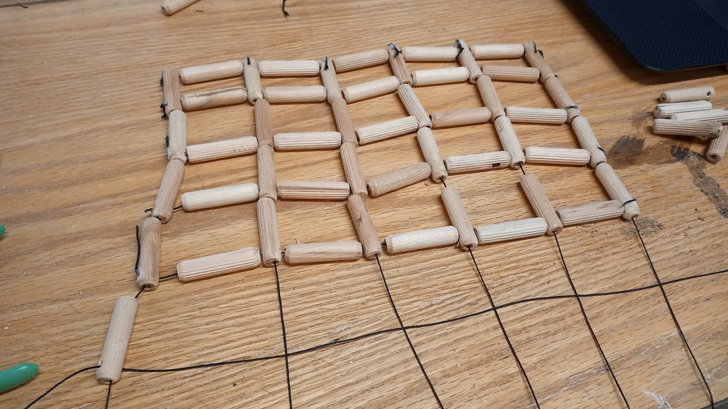
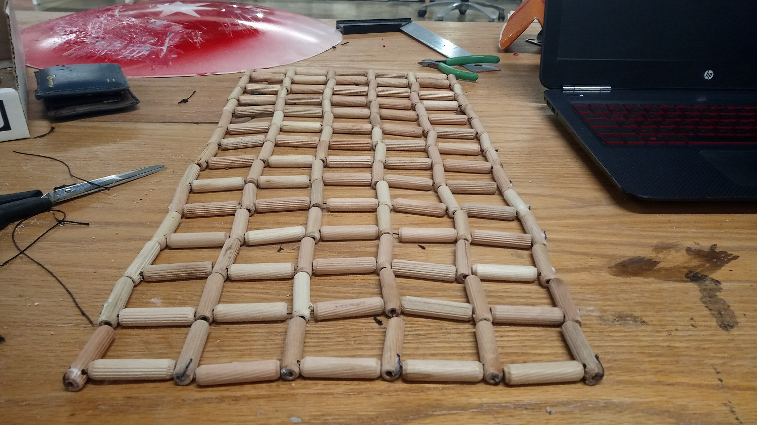
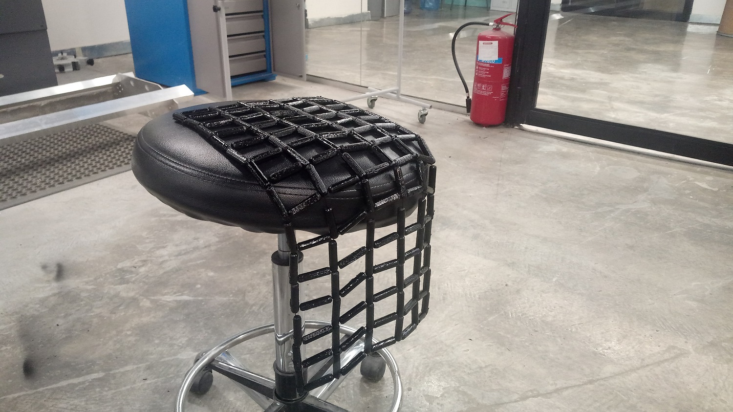
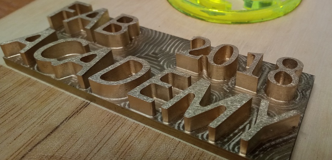
This is the final result after painting and holding :D
Also I want to make a metal piece infront of my project so I started design using Fusion 360 its a simple design for an extruded text in order to mill the text using Tormach PCNC 1100 , here we go
After I wrote the text using fusion 360 I made extrude then I went to the CAM process in fusion, then I used 2D pocket, the material that I want to mill is cupper so in order to mill the material I have to know the speeds limits or the recomended speeds.... to calculate the speeds for the bit that I want to use which is 3/32" flat 2 flutes carbide endmill
I have the table below
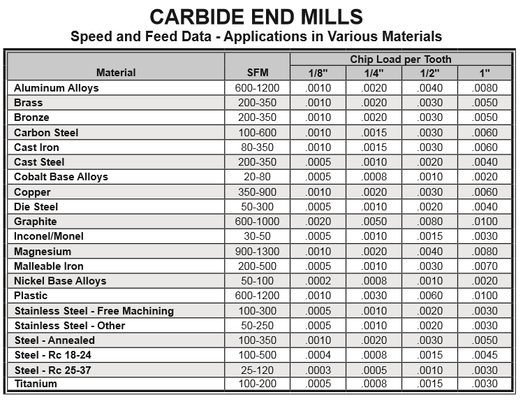
for copper the SFM (V) is 900 so if we calculate the RPM depending on V we get:
RPM= (12*V)/(3.14*Diameter of the tool) //D=3/32 and V=350-900 so we get RPM of aproximatelly 11000-36000rpm .. in order to calculate the feed rate we use this equation :
Feed= RPM*numberof flutes*chip load..... Feed=(11000-36000)*2*.001= (10-72) inch/min
I used the maximum RPM of 5000 and feed rate of 34in/min = 800mm/min
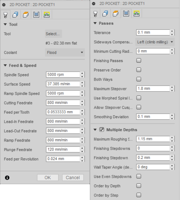
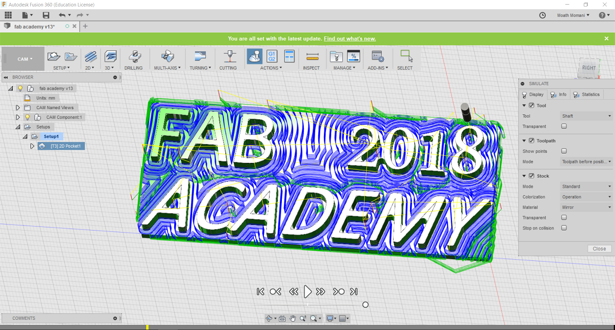
And this is the generated tool path
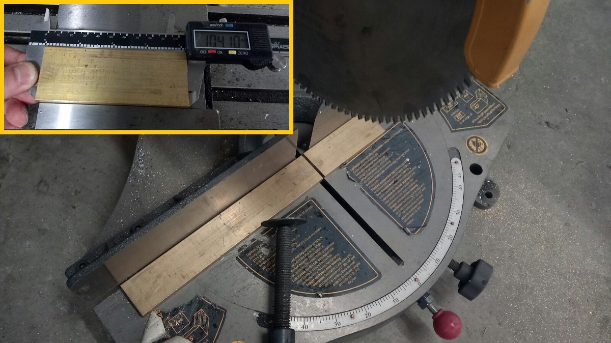
then I used a manual saw to cut the raw material as the same as the dimension of my design 104mm*40mm
After I put the workpiece in the machine holder and I set the x and y zero and z axis zero and then I started the milling process
For more details about the milling machines and how to use the right end mill and the speeds you can visit this Link
Download fab academy logo fusion file
5.3D Printing
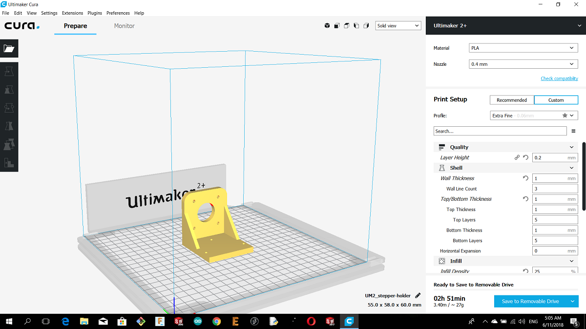
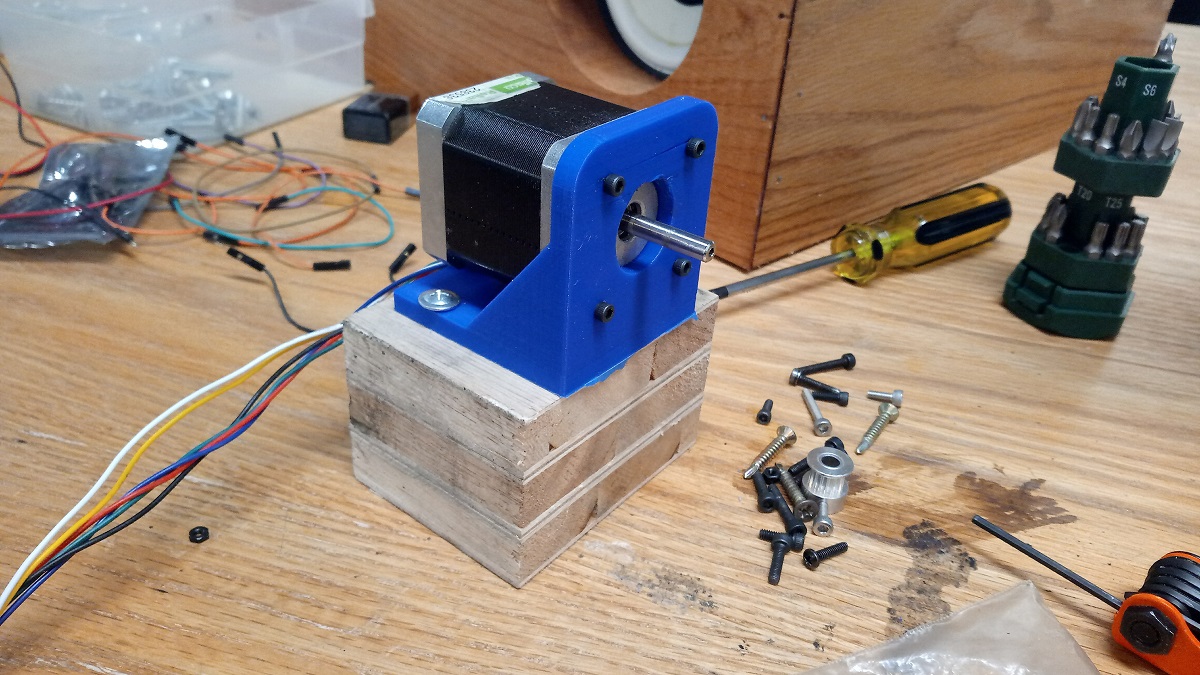
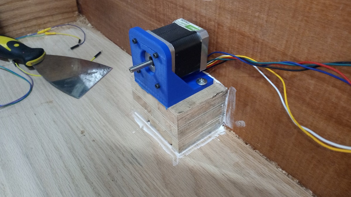
For my project I need a holder for the stepper motor nema 17 so I have designed a holder in the cad section and I want to manufacture this part using 3D printing technology, here is the part
I made the part with blue color as the same as the PLA material color and I will use Ultimaker2+
Because all the load will be on the holder I increased the infill of 25% and here is the printing variables
Nozzel 0.4mm
Material PLA
Infill 25%
Top/Bottom thickness 1mm
Wall thickness 1mm Layer height 0.2
For more details about the 3D printing technology you can visit this Link
Download
stepper holder stl
6. Laser Cutting
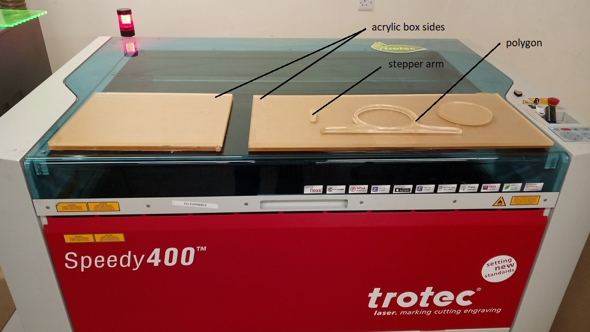
In my project there are many parts I want to make them by laser cutter for example the outside acrylic box and the motor parts as shown in the next picture
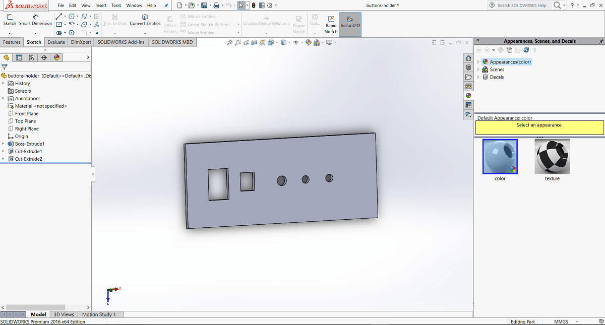
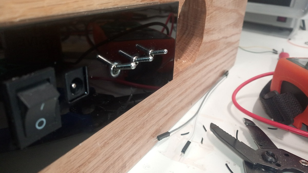
Also, I want to add additional part here, which is a holder for switches
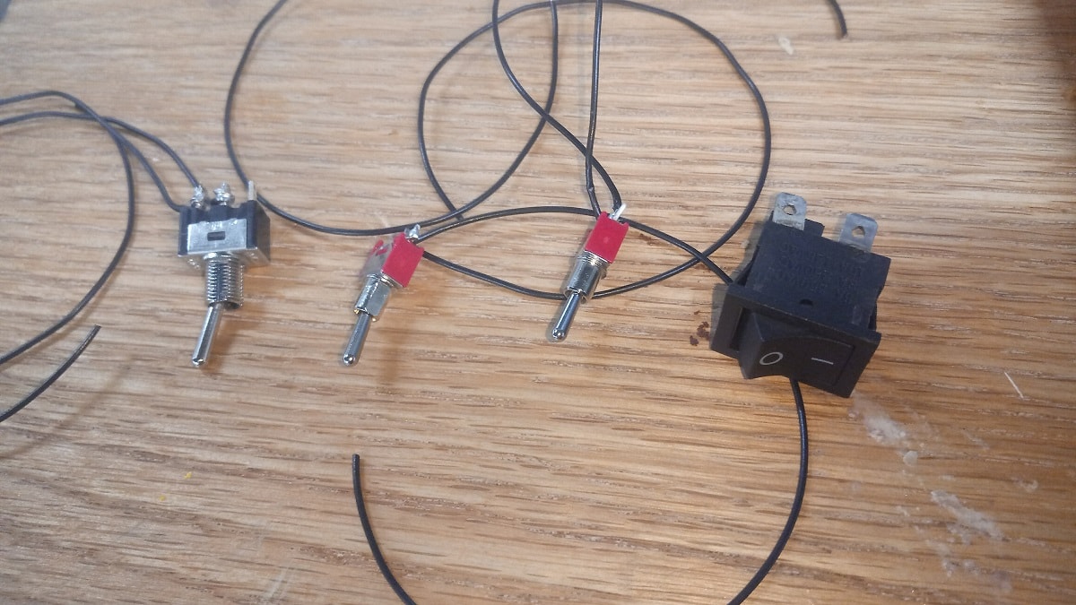
So using solidworks I designed the holder for them
the main switch will be the responsible about the power on/off and the other 3 switches are for RGB strip so they are connected with the ground separately so you can change the color of of the LED
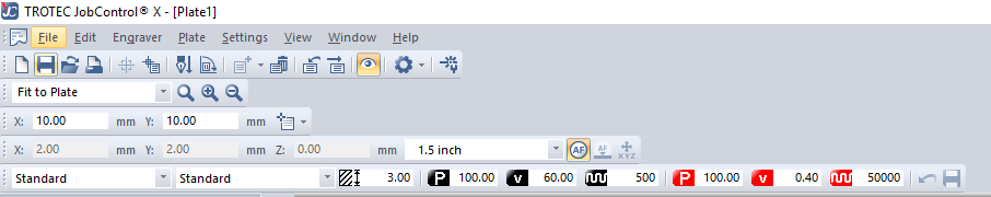
Using Trotec engraver speedy 400 here is the cutting variables fot 3mm black acrylic
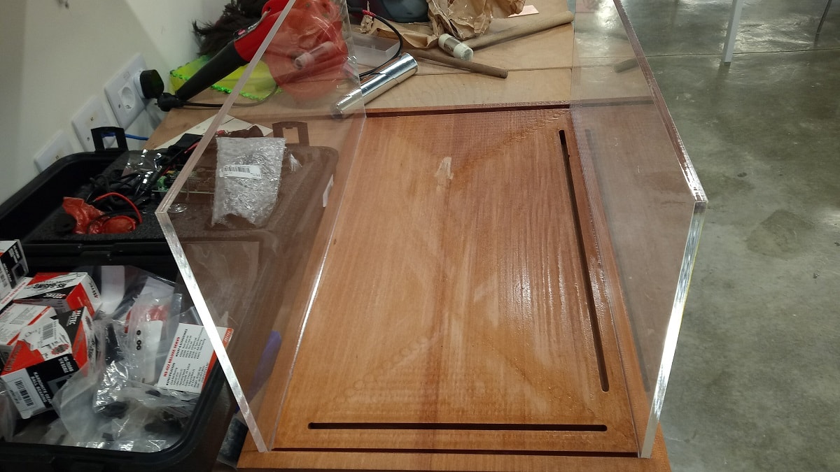
Next I started with the out side box and the inside components after I saved them as Dxf
The acrylic thickness is 8mm so the cutting variables that I used are :
Power 100%
Speed 0.18 Lense 2" Frequency 60k
look at the clearance between the slots and the acrylic how much they are perfect :D
For more details about laser machine you can visit this Link
Download acrylic1.dxf and acrylic2.dxf for the sides of the acrylic box
Download top acrylic plate.dxf
Download switches holder.dxf and sld part
Download stepper arm.dxf
Download polygon.dxf
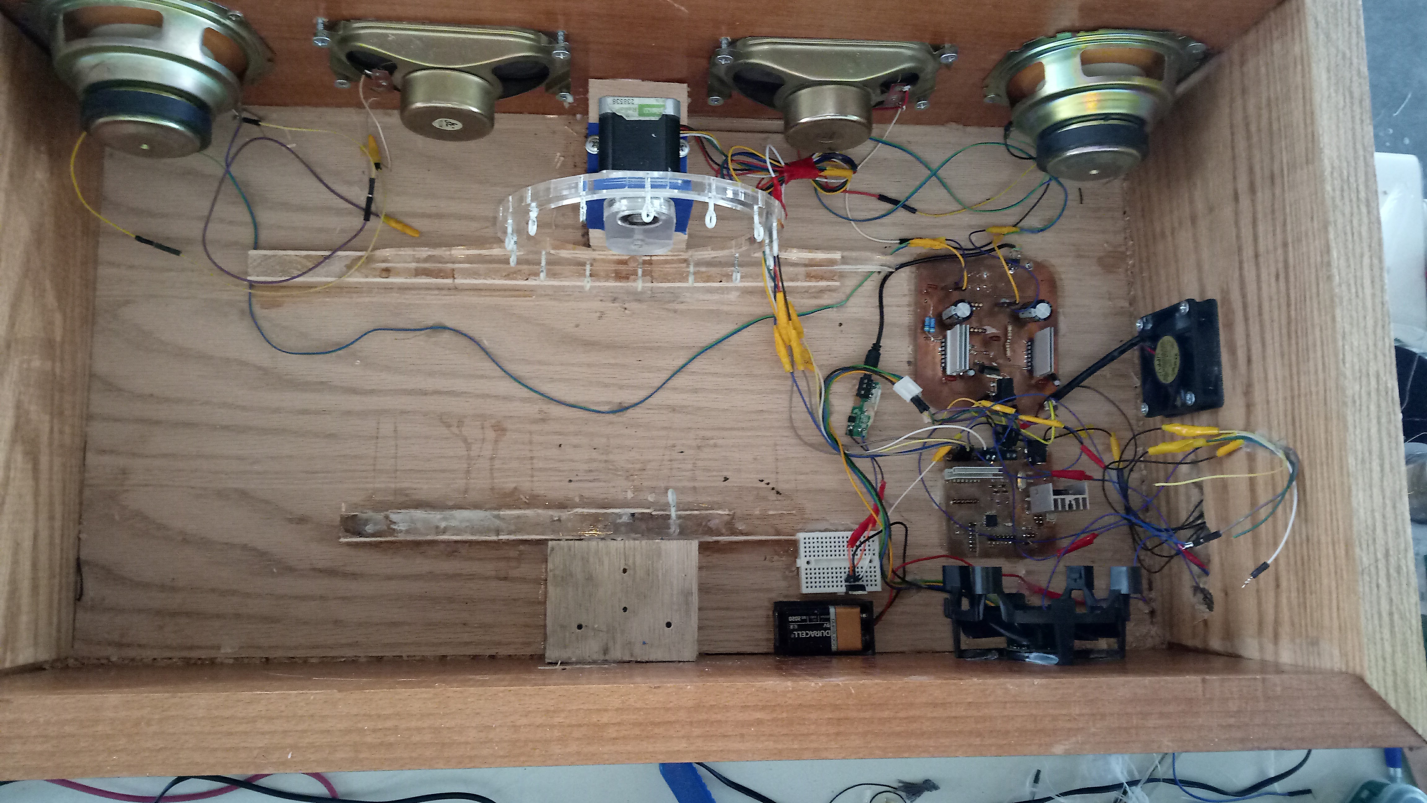
7. Project Assembly
After I have finished all the manufacturing processes and I got all the parts its time to join them together
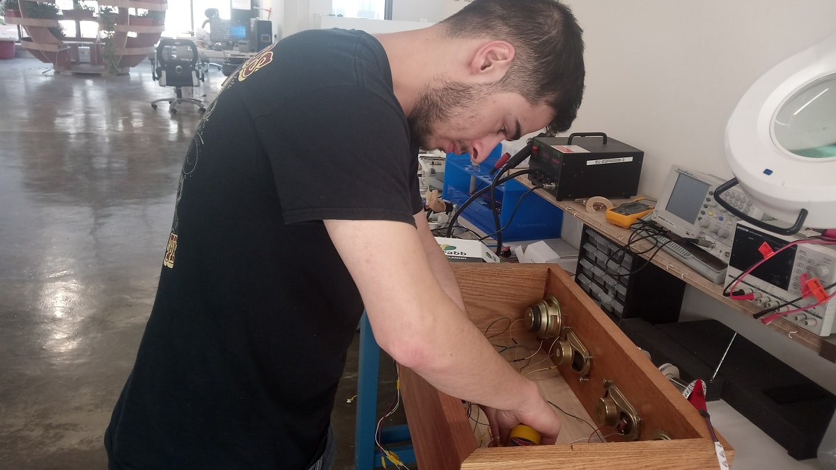
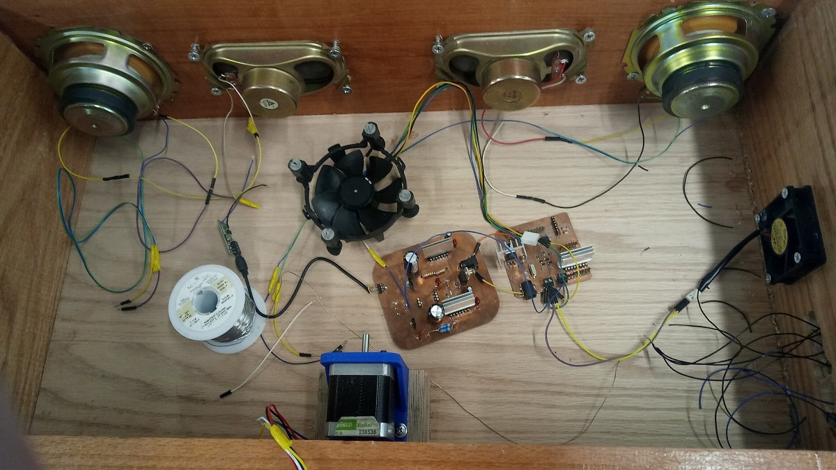
The first thing I started with is the speakers so I have 4 speakers 6watt 8 ohm
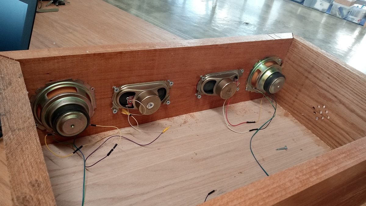
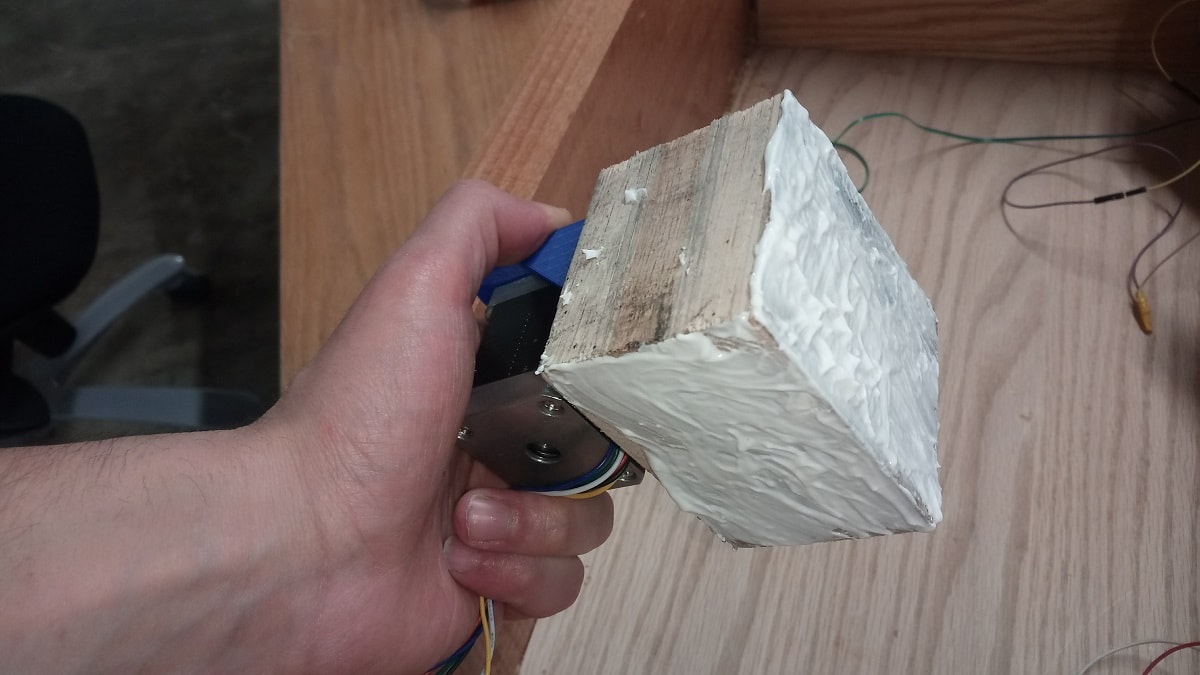
After I finished the speakers I started with the motor so I glued 3 plates of wood with each other and then I glued the motor in the center of the wood box
After I connected the fans and I also connected the speakers with the amplifier board also I connected the amplifier board with the output voltage of the arduino board(12v)
Then I connected the switches with the holder
After I connected the stepper motor with the arduino board and the RGB strips with the switches and the switches with the ground pin in arduino
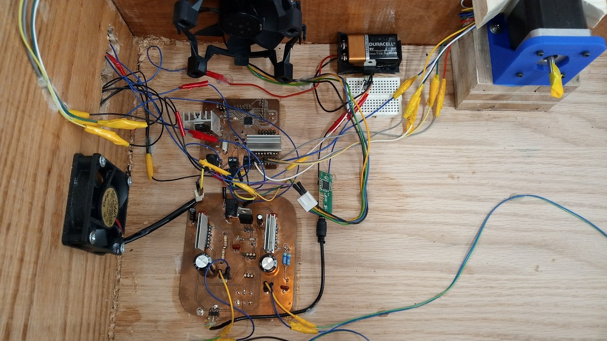
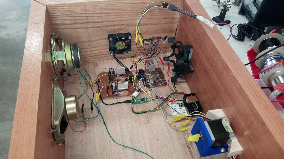
You can see a 9V battery in the box and it's connected with a voltage regulator 5V in the breadboard, I did that to avoid the ground loop that I mentioned it in the sound system section, so I isolated the Bluetooth circuit from the amplifier circuit to avoid GROUND LOOP and fixing it needs DC to DC isolating converter and without it the board will create a nasty interference noise!! so in my case I could not get this isolator so I used a battery
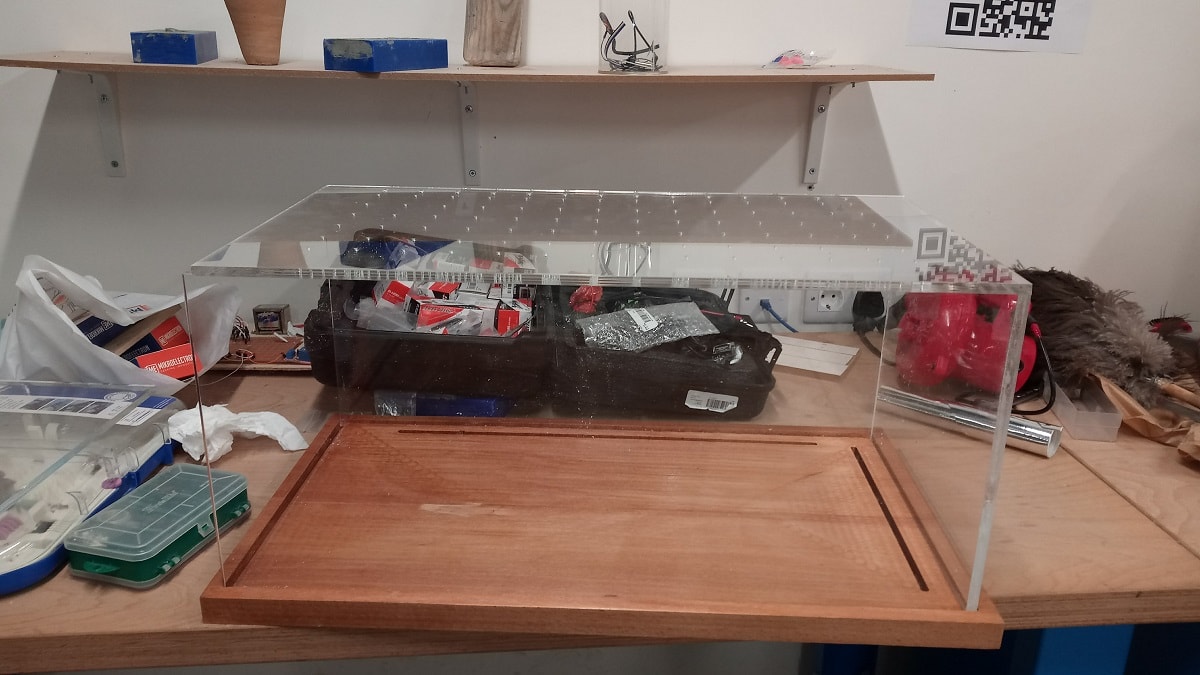
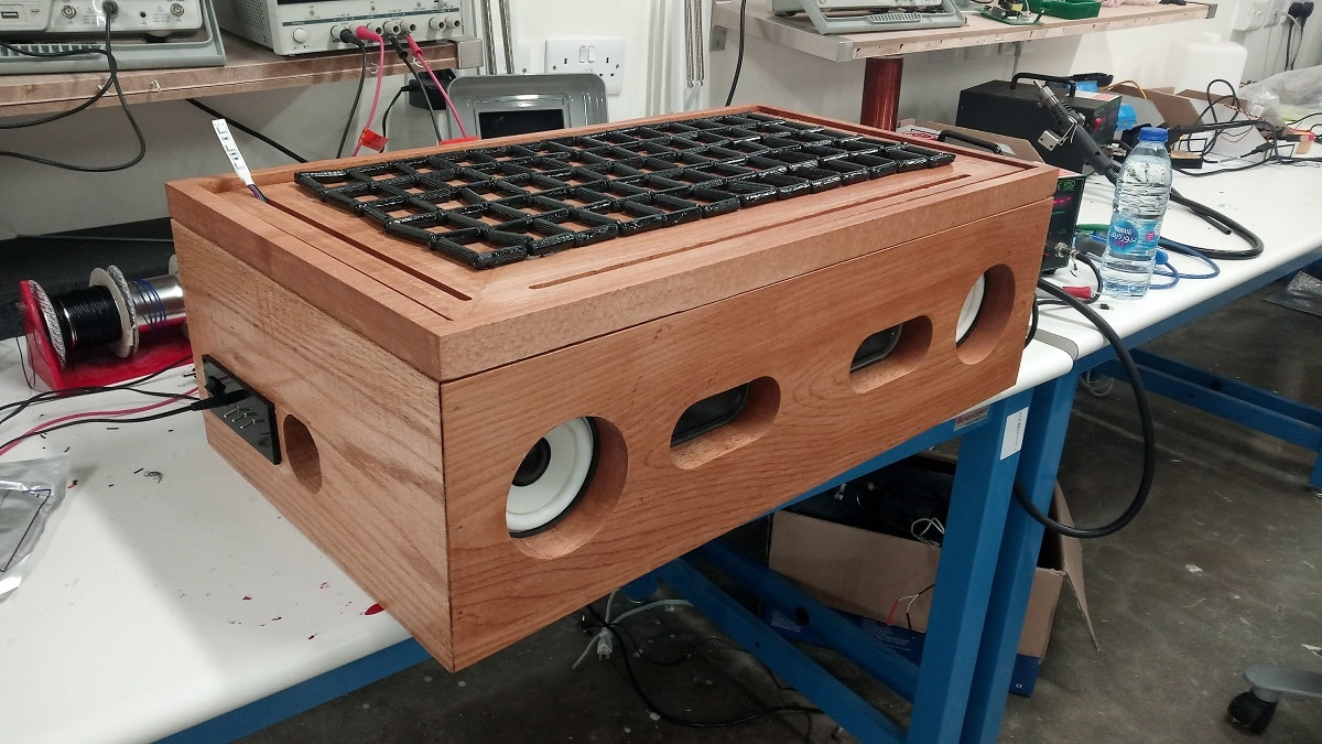
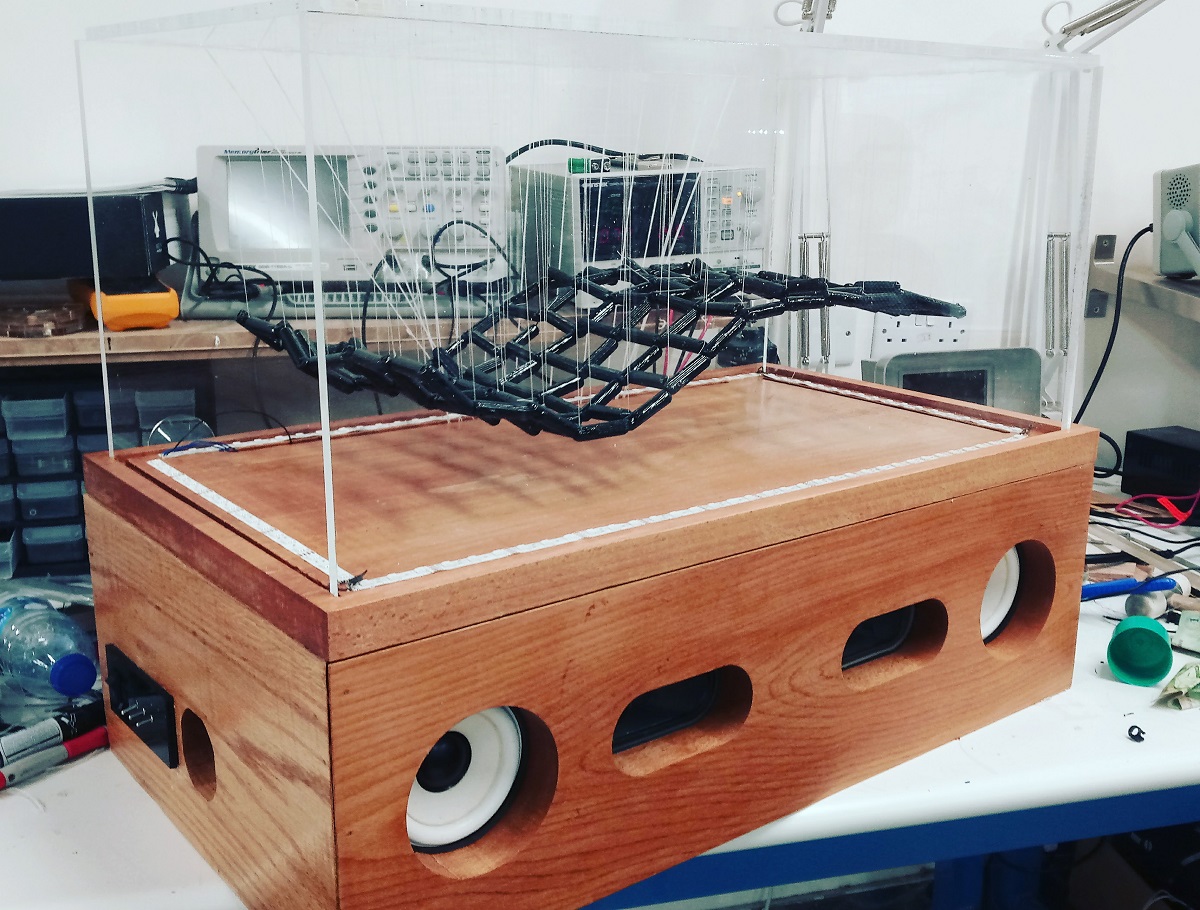
However look at the box how much beautiful is it :D
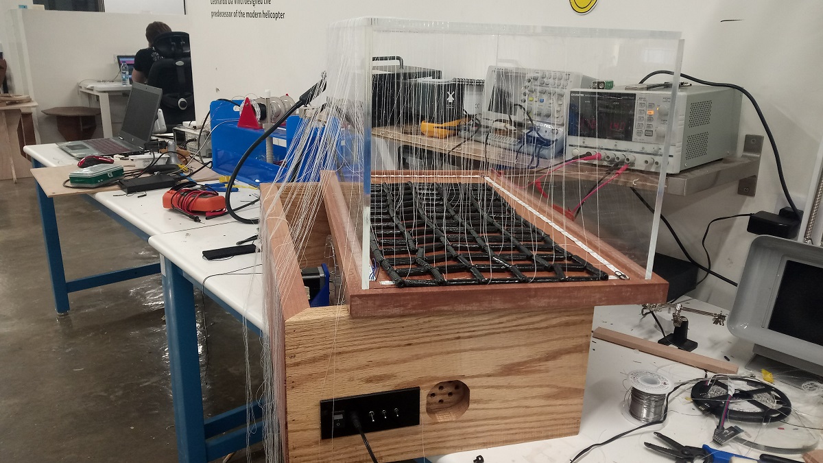
Now I started with the acrylic
I used these pieces for wires connections
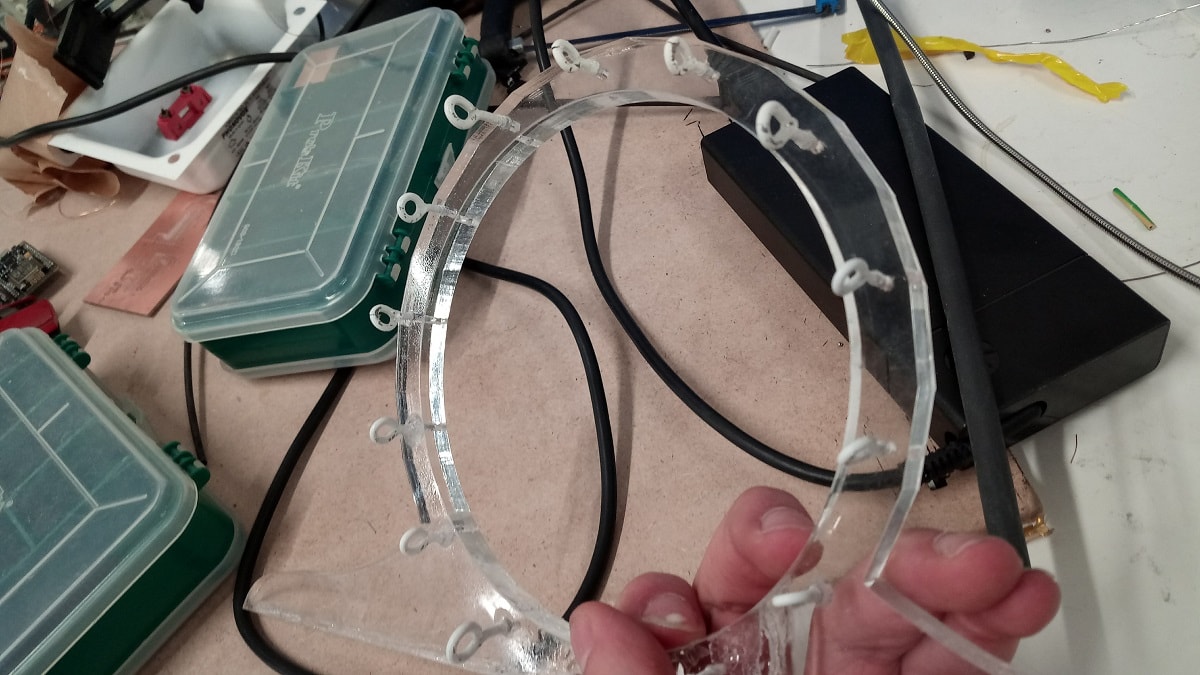
The next step is to connect the LED strips
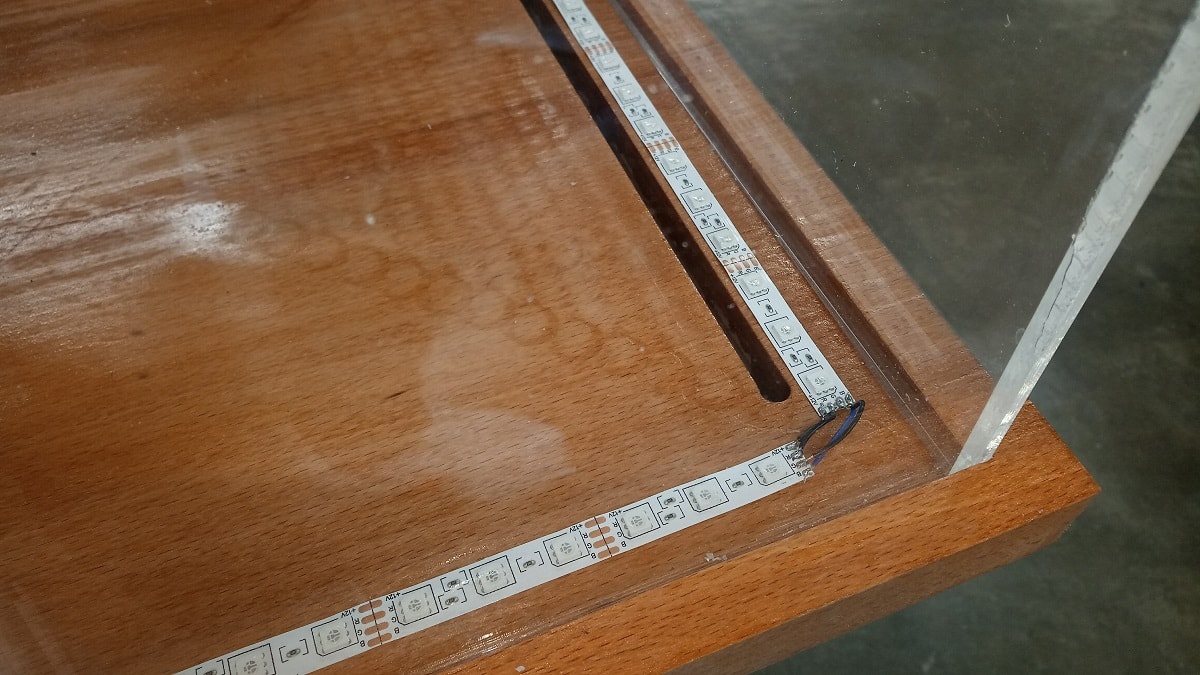
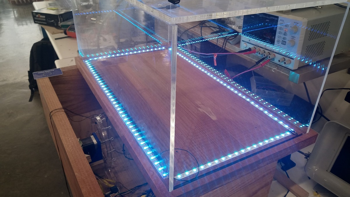
I can change the LEDs to 8 colors by the switches however after that I started with the wiring
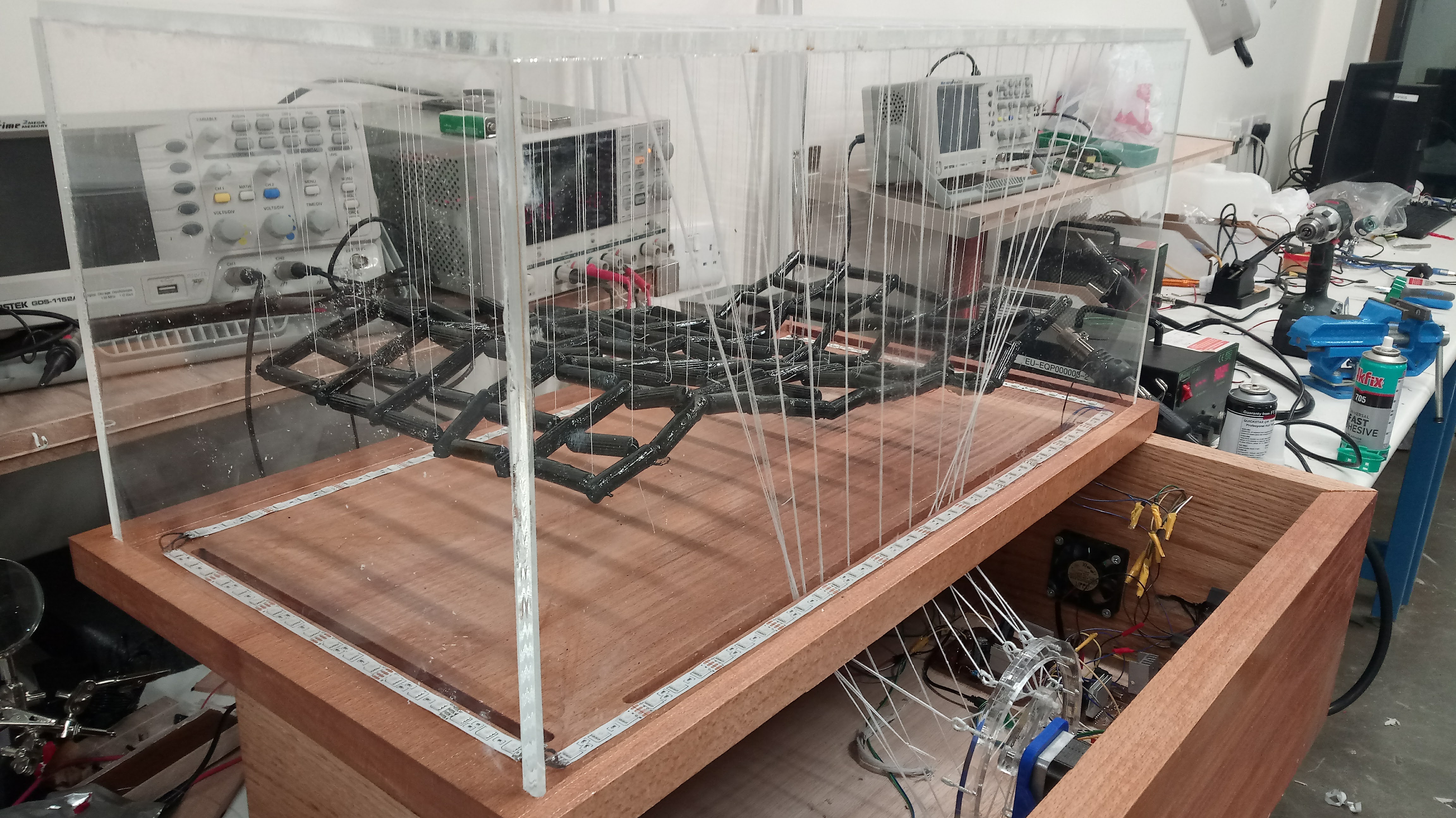
Finally this is my project
8. Programming
Now I want to set the stepper at a good speed fits the wave motion for my project so I tried different speeds and the best speed in my opinion is 7 RPM so I programmed the stepper motor using Arduino c to rotate 7 RPM, and here is the code
#include <Stepper.h>


const int stepsPerRevolution = 200;  // change this to fit the number of steps per revolution for your motor


Stepper myStepper(stepsPerRevolution, 7, 8, 9, 10);
#define led 4
#define port1 5
#define port2 6
void setup() {

  // set the speed at 7 rpm:
  myStepper.setSpeed(7);

  Serial.begin(9600);
}

void loop() {
  // step one revolution  in one direction:
  Serial.println("clockwise");
  myStepper.step(stepsPerRevolution);
  digitalWrite(led,HIGH);
  digitalWrite(port1,HIGH);
  digitalWrite(port2,HIGH);


}
On my board I designed two power MOSFET IRLML6244TRPbF connected to pin 5 and 6 in the IC so I can turn the terminals off and on by the code and what happen when I write in the code digitalWrite(port1,HIGH); digitalWrite(port2,HIGH), the mosfet will connect with the ground and the 12v is already connected so the terminals will output 12 volts
For more details about the stepper motor and programming you can visit this Link
Download the Code
9. Problems
The wires generate a high friction so the motor can't rotate so what I have done to reduce the friction is to change the angle of the wires
If we notice here we see the motor wires has an angle of 90 degrees with the top acrylic plate when we close the box, so what I have done after to avoid this problem is to change the place of the motor so the angle will be more than 90 degrees.
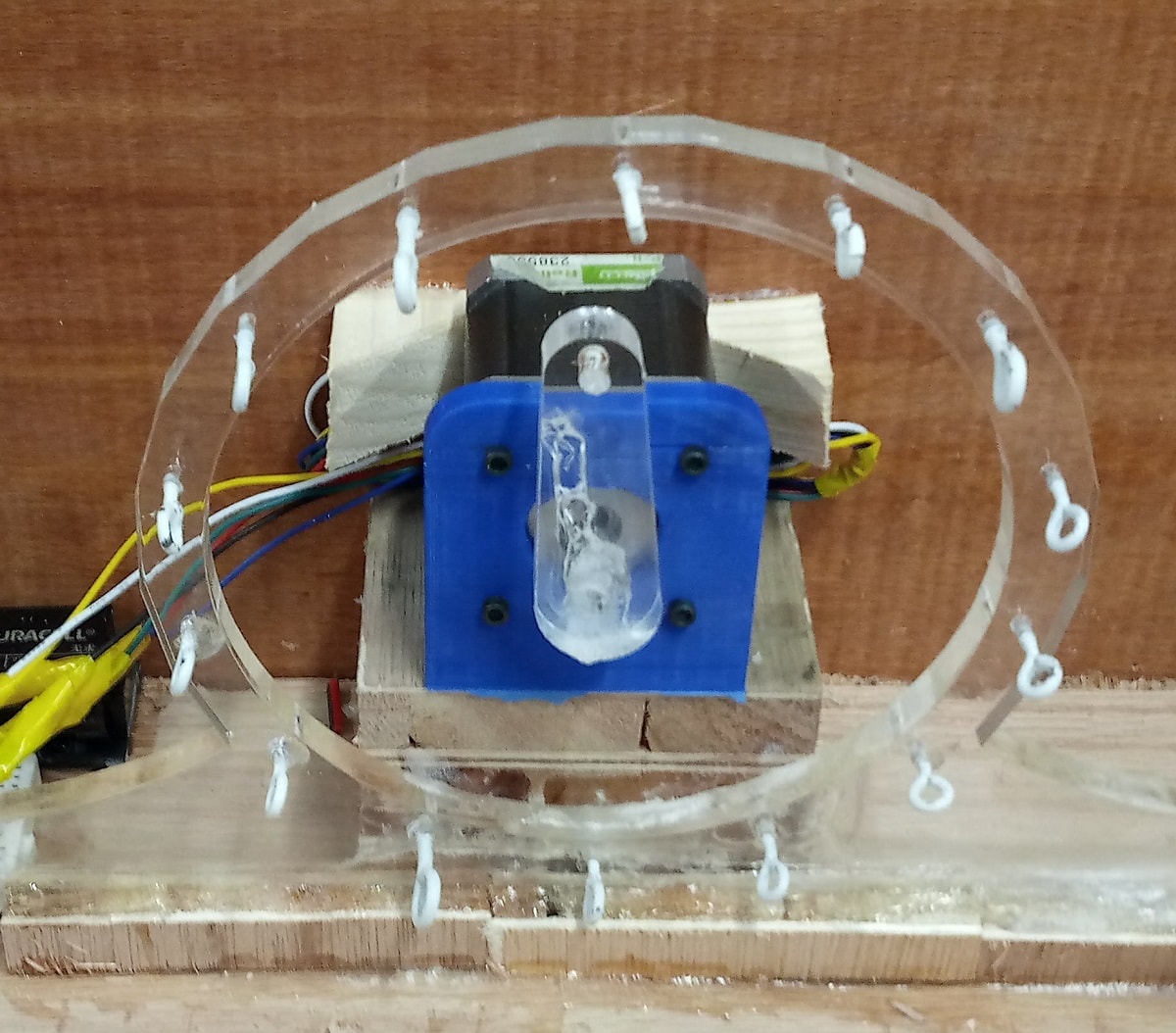
This is the new place for the motor
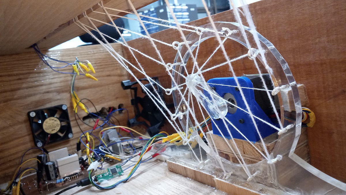
The second problem is the type of the wires because the used wires are light and not strong wires, so I replaced the white week wires with grey strong wires as shown
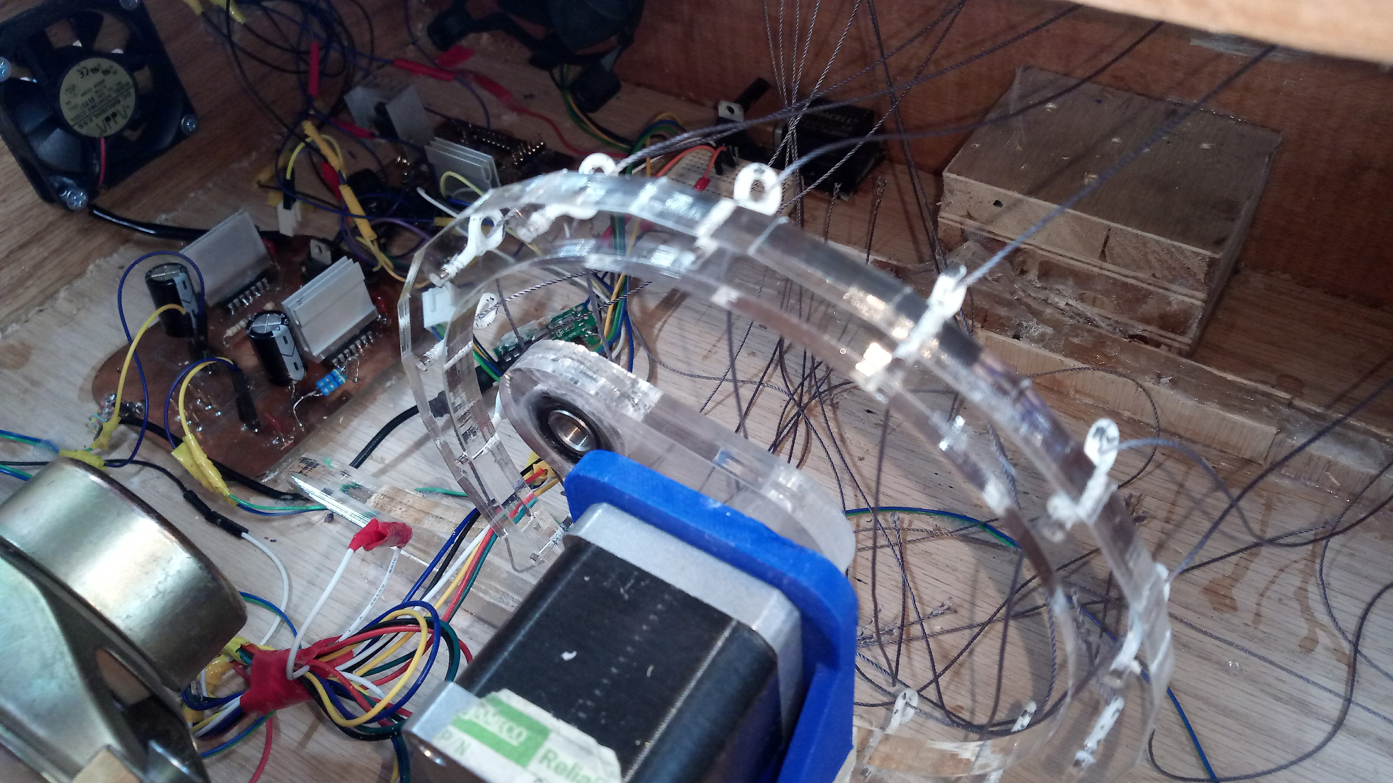
Also, I have changed the stepper arm and I integrated a bearing on it because when the motor rotate then the wires didn't make a rotation in the armhole, so I think the bearing will solve this problem
this video shows the smooth motion after solving the problems :D