1.Board design And Cam
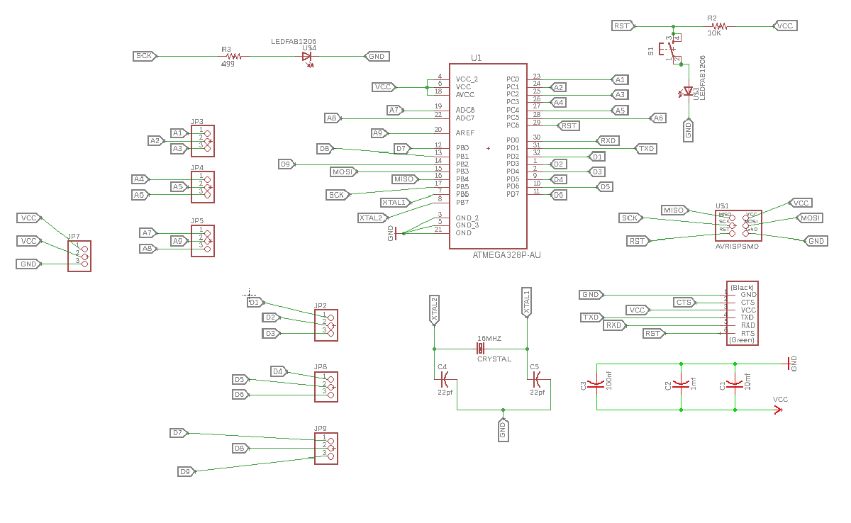
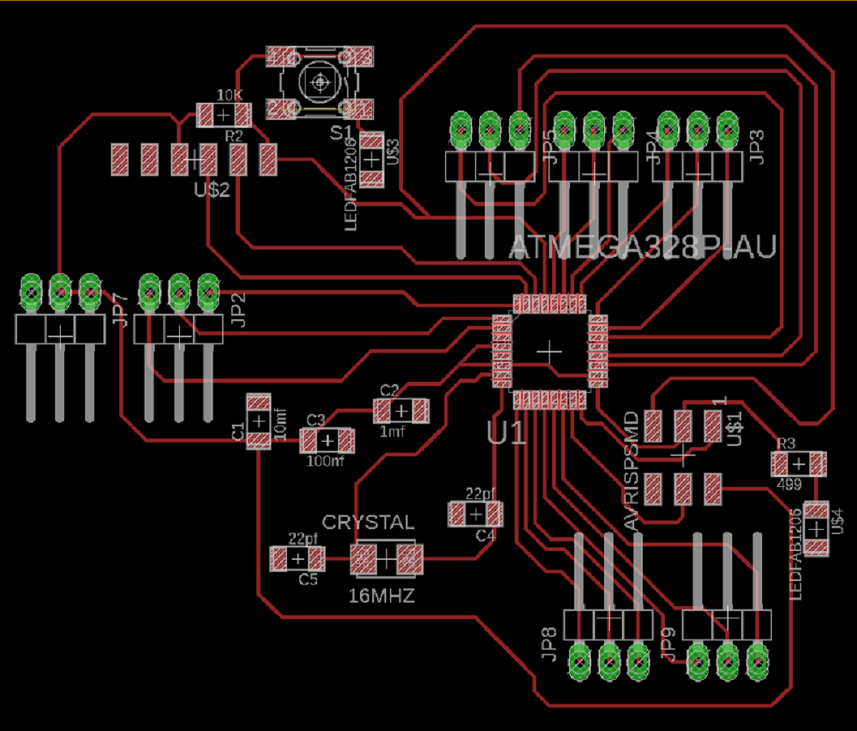
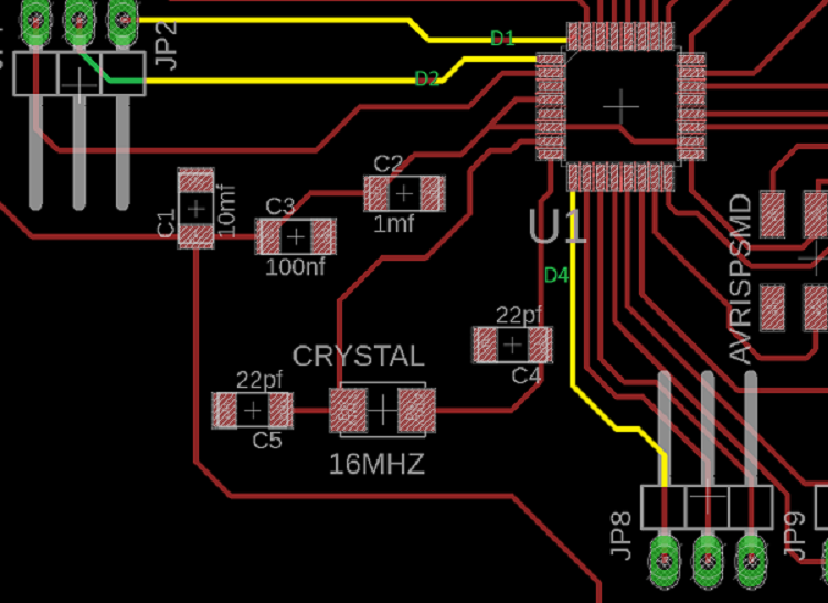
Using autodesk Eagle I designed a board with Atmega 328p and here is the schematic and board designs:
I used roland SRM-20 to mill my board, for the traces the bit was 1/64" ball nose and for outside or contour cut it was 1/32" flat and the board thickness was 1.7mm.
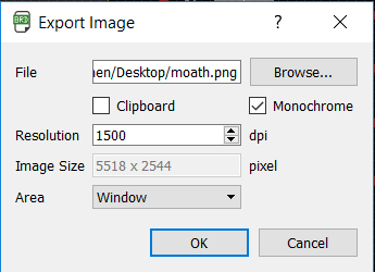
From board layout I export the board design as image
After I edited the image in paint to get the inside cut
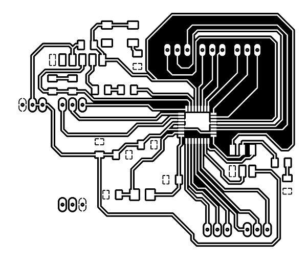
And the outside cut

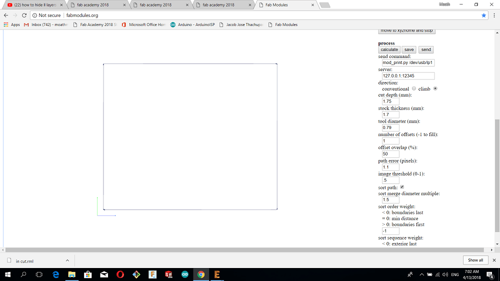
then I went to Fab modules to generate the toolpath.
#INSIDE CUT with depth of cut of .05mm
#CUTTING feed rate of 4mm/sec
And I chose climb mill to get better finish for my board

#OUTSIDE CUT with cutting feed rate of 0.5 mm/s and also I chose climb milling and the bit diameter 0.79mm
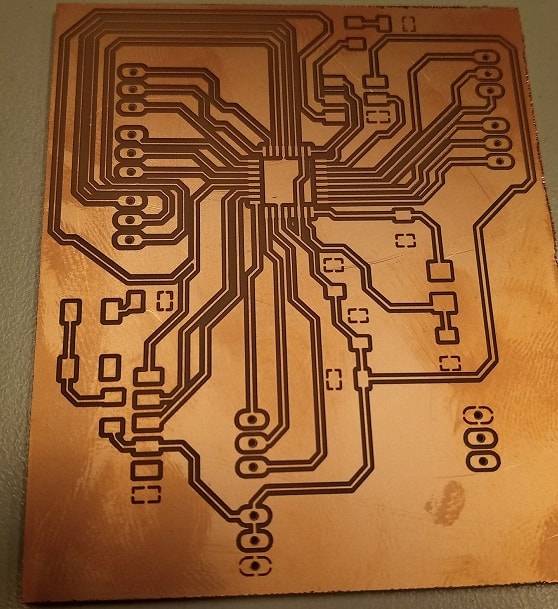
And here is my board
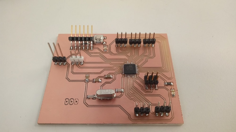
the components that I used :
1.IC Atmega 328p
2.One resistor 10k ohm
3.RST button
4.pin header
6.Two LED
7.Crystal 16Mhz
8.Two capacittors 22pf
9.One cabpacitor 1mf
10.One cabpacitor 100mf
11.One cabpacitor 10mf
12.One resistor 499ohm
2.Programming DC Motor
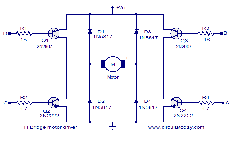
I'm going to program a DC motor in which i will make the rotation of the motor in two directions by changing the pins for example if we changed the polarities then the direction of rotation will reflect and for thet we can use H bridge drive circuit
But I will use L 298 motor driver And then I will make a change in the rotation speed by using analog pin.
For Atmega 328 this is the pin out
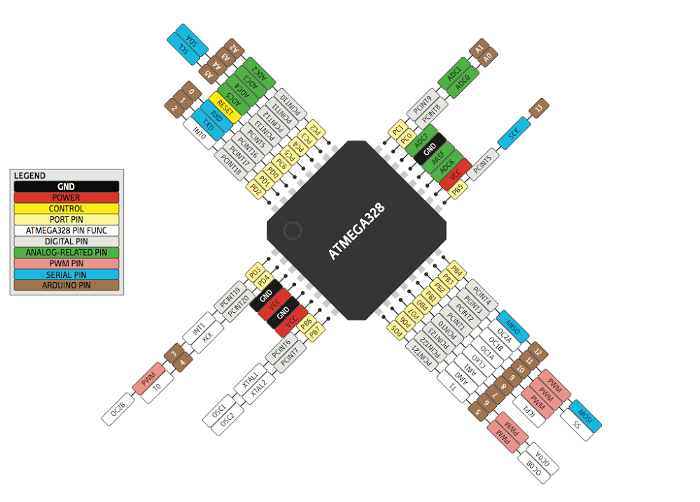
#RST pin with arduino pin 10
And this is L298 motor driver
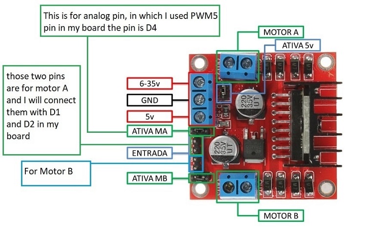
D1 and D2 are for digitat pins and D4 is analog pin
After my demonstration lets do programming :D
I used the arduino as isp then I uploaded the code
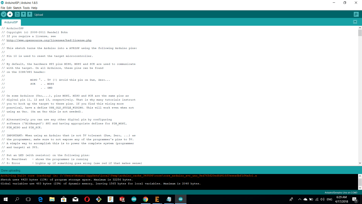
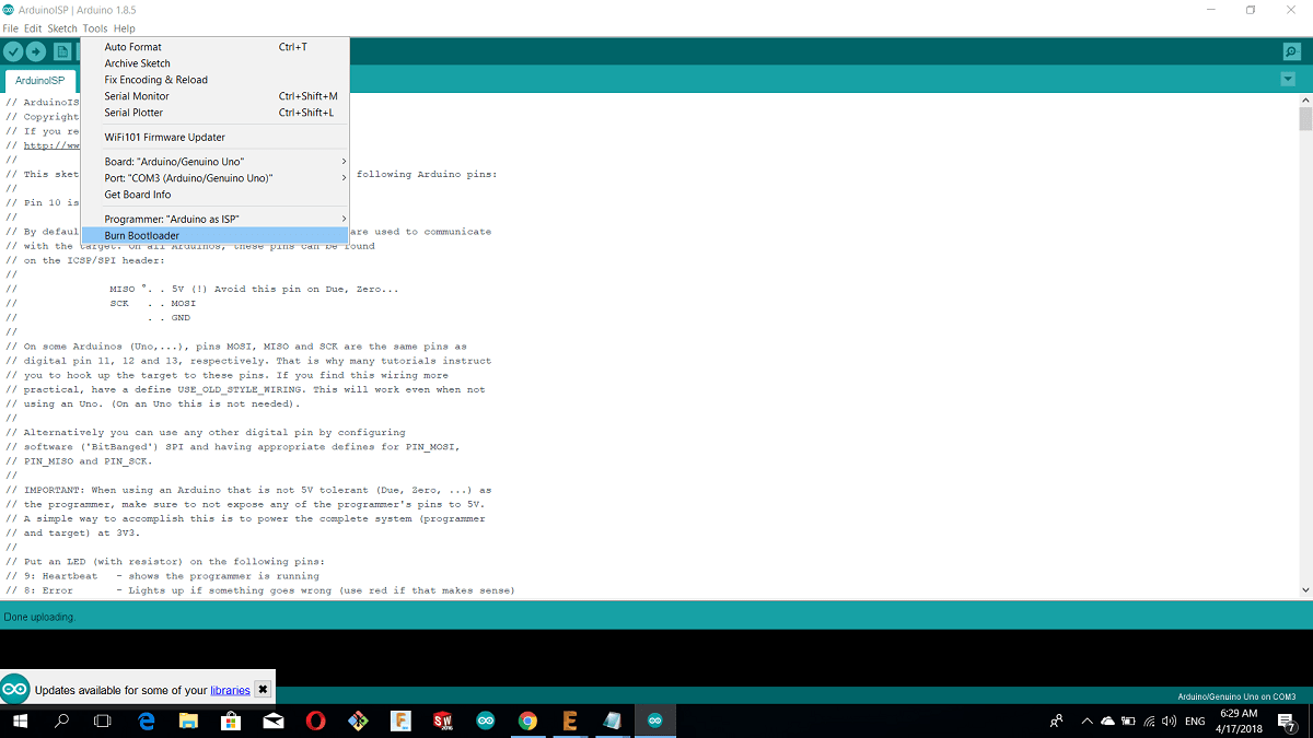
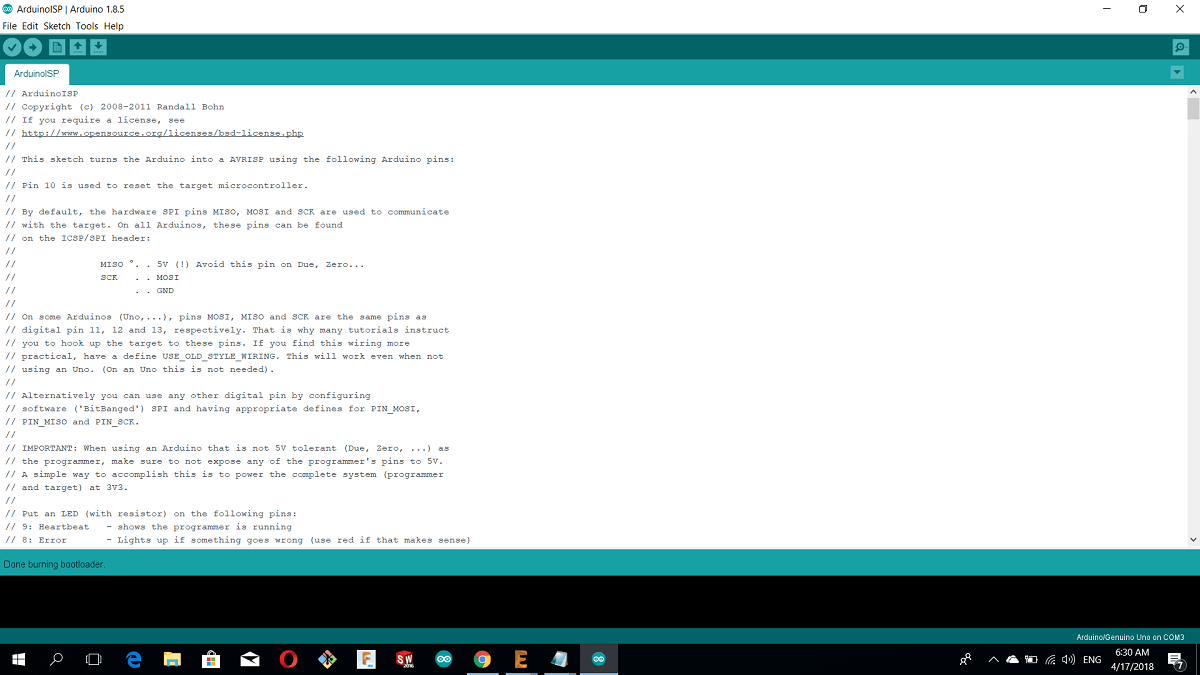
Then from tools I chose the following and then Burn bootloader
Then I wrote a simple code using arduino c to make a rotation
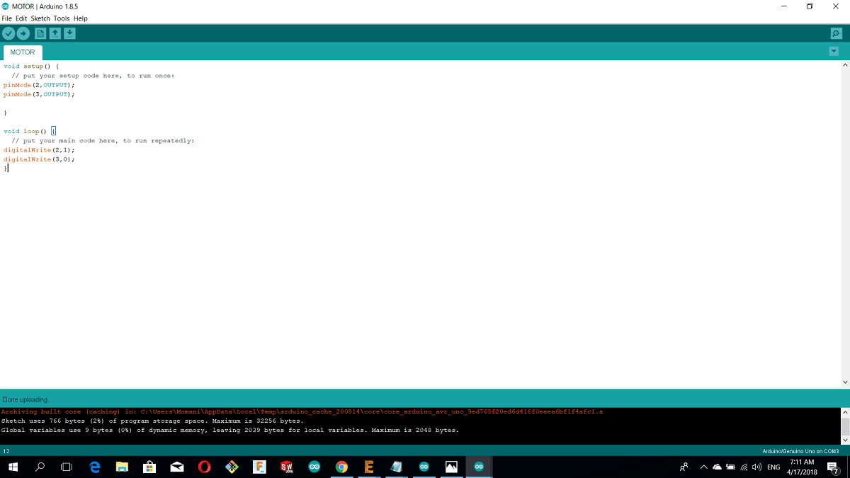
In the loop function,the pin 2 is high and pin 3 is low that mean the motor will keep the rotation in one direction
Then uploading using a programer
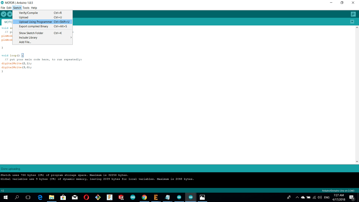
Now I will make the rotation by both directions with a delay of 2 seconds
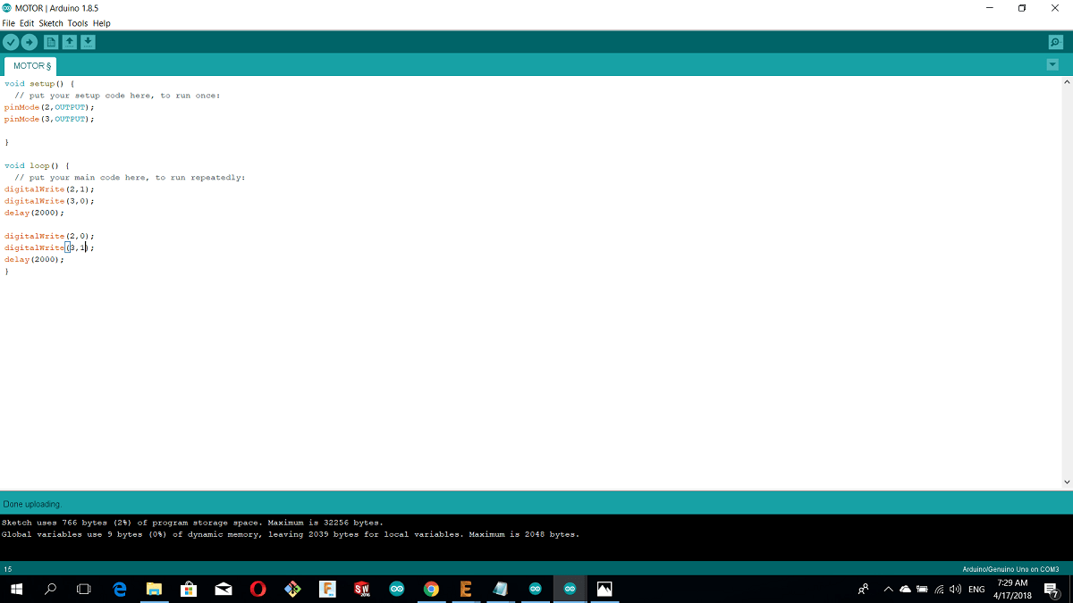
In the loop function, I added another direction of rotation by swiching the pins mode high to low - low to high
Now the 3ed code i will use the analog pin which is pwm 5 in my board D4 to slow the rotation in one direction and make it faster in the other direction
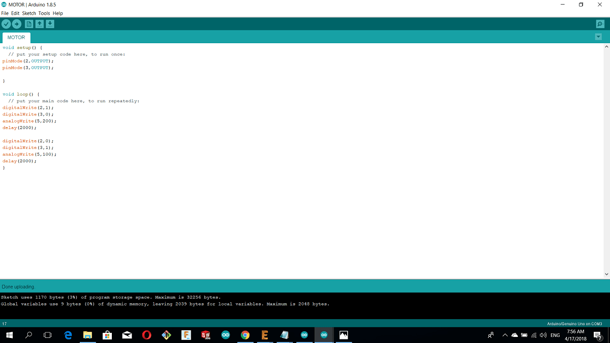
the connection in this code the power sorce is connected with 5v port and GND in the L298N and the PWM pin connected with ATIVA MA and pin 2 and 3 with MOTOR A in L298N
3.Programming 2Leds Using Potentiometer
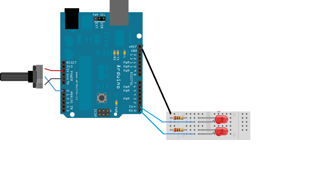
I used arduino uno with potentiometer,2 lids and 2 resestors.
I connected the GND from arduino with the breadboard and I used arduino digital pins 0 and 1 are connected with the 2 led and the 2 resestors of 150 ohm connected with the led and GND in breadboard
For the potentiometer I connected the GND and VCC of 5v with arduino and the middle pin with A0, the next picture shows the connections
I just used two leds with arduino pin 0 and 1
this is the code
int sensorValue = 0;
void setup() {
pinMode(0, OUTPUT);
pinMode(1, OUTPUT);


}

void loop() {
  digitalWrite(0, HIGH);
  sensorValue = analogRead(0);
  delay(sensorValue+25);//sensorValue used for delay and any faster didn’t look right
  digitalWrite(0,LOW);
  delay(15);

  digitalWrite(1, HIGH);
  sensorValue = analogRead(0);
  delay(sensorValue+25);
  digitalWrite(1,LOW);
  delay(15);

}
s
4.Programming A Stepper Motor
In our fablab we have variaty types of stepper motors and I used the 4 wires bipolar stepper motor from JAMECO
JAMECO 2-Phase 5VDC 1A Bipolar Stepper Motor 237490
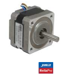
and the motor features are:
Rated voltage: 5VDC
Step angle: 1.8° ±5%
Phase resistance: 5Ω
Current: 1000mA
Detent torque: 150 g-cm
Holding torque: 1800g-cm
Mounting hole space: 1.22"
Mounting holes: 0.10"
Shaft diameter: 0.20"
Shaft length: 0.91"
Motor diameter: 1.54"
Motor depth: 1.34"
Weight: 0.44 lbs.
Screw Mount Dimensions: M3
I used also l298.
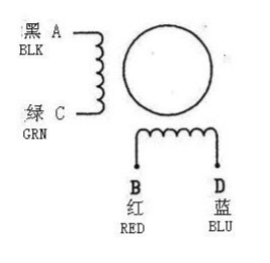
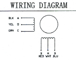
from the data sheet I Knew the coils wires
Again this is l298
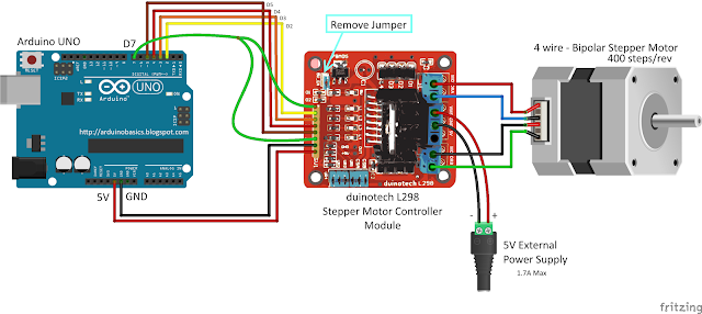
This is the connection between l298 and stepper with arduino
I used this code
Code explanation
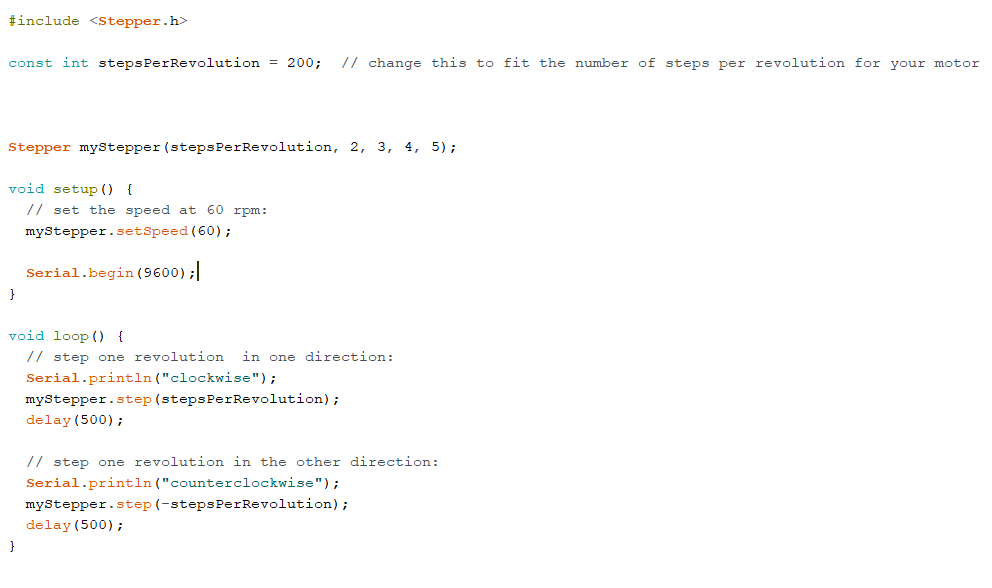
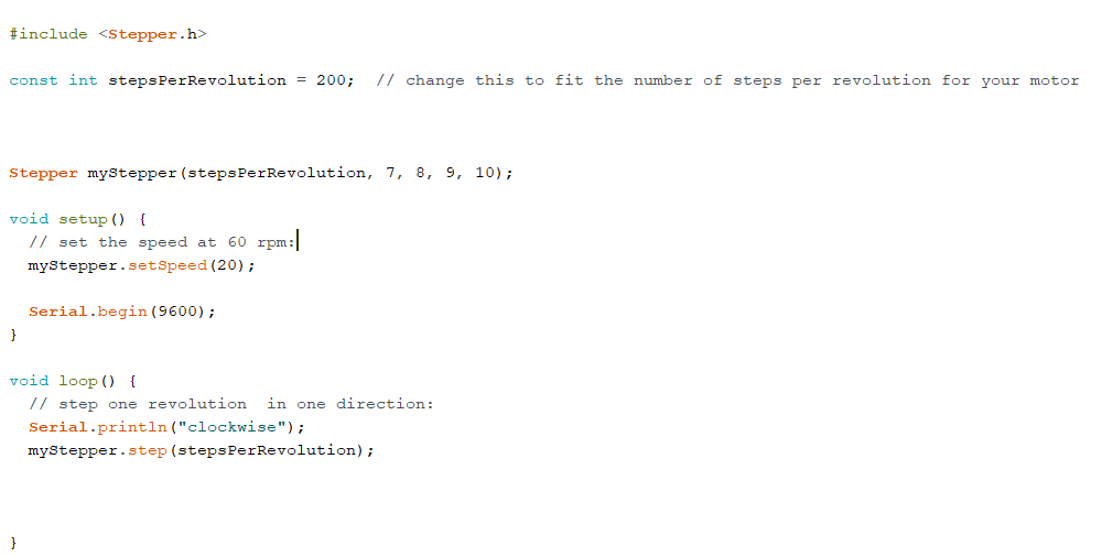
The firs thing I included the stepper library in the code (include stepper.h)After I defined a constant integer variable for steps per revolution... It is important to know how to calculate the steps per Revolution for the stepper motor because only then you can program it effectively.
Steps per revolution = 360/step angle
Here, 360/1.8(from data sheet) = 200 steps per revolution.
After we have the stepper function
Stepper(steps, pin1, pin2, pin3, pin4)
This function creates a new instance of the Stepper class that represents a particular stepper motor attached to my Arduino board. it is used at the top of the sketch, above setup() and loop(). The number of parameters depends on how you've wired your motor, in my case I have 4 wires.
Parameters
steps: the number of steps in one revolution of my motor that I have calculated it.
In void loop function we have :
Stepper: setSpeed(rpms)....Sets the motor speed in rotations per minute (RPMs). This function doesn't make the motor turn, just sets the speed at which it will when you call step().
Now I will call the step function myStepper.step(stepsPerRevolution); turns the motor a specific number of steps, at a speed determined by the most recent call to setSpeed() above the void function
steps: the number of steps to turn the motor...positive to turn one direction, negative to turn the other
Then I uploaded it to arduino and I removed the usb from my pc.
5.problem?!
Yea I had I big problem I forgot to add a capacitor of 100uf connected with RX so because of it I couldnt use the FTDI cable and I used the Arduino as ISP to program my board after I made another board and I have equiped ULN2003UN on it
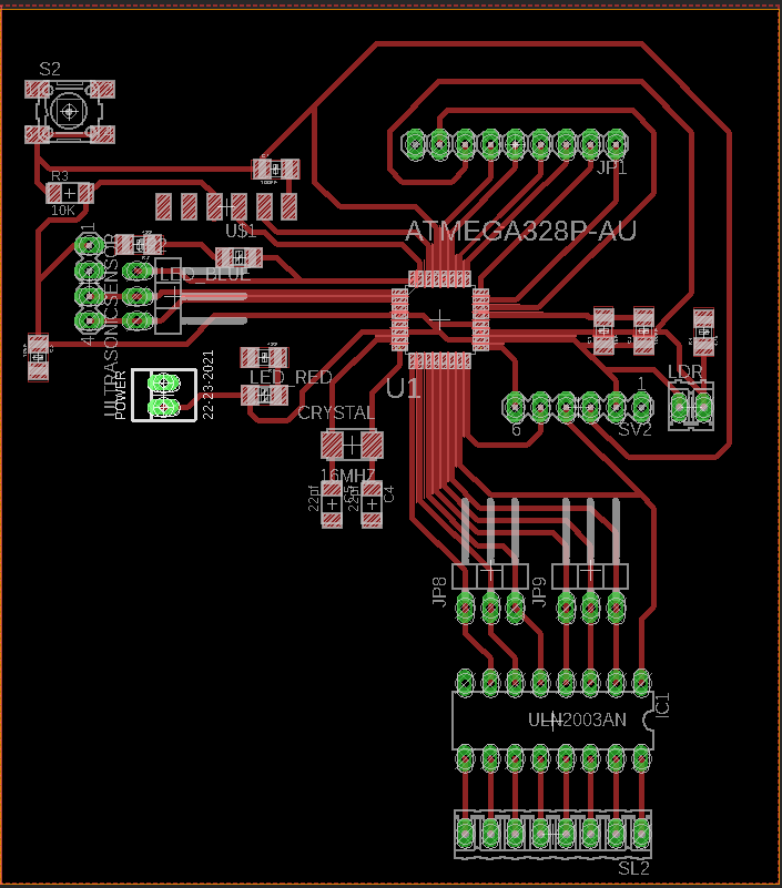
Using autodesk Eagle I designed a board with Atmega 328 and I added 4 pins for ultrasonic sensor which are the VCC, GND and pins 3 and 4 in atmega 328 pins out also I added LDR sensor connected with AD6 also I integrated my board with ULN2003AN and here is the schematic and board designs:
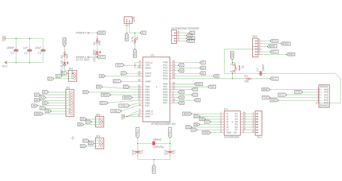
and this is Atmega 328ap pins out

After I designed my board I used the cam processor FLAT CAM
In order to use flat cam I have to get the cam files from eagle - Board layout - file - generate cam date
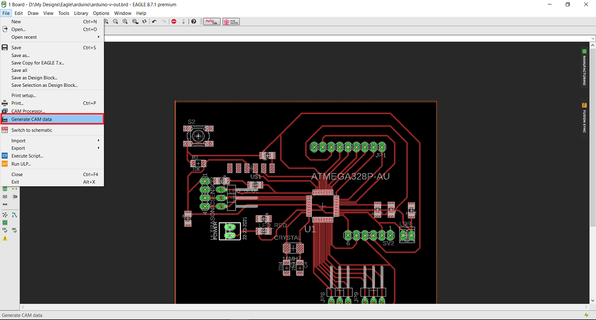
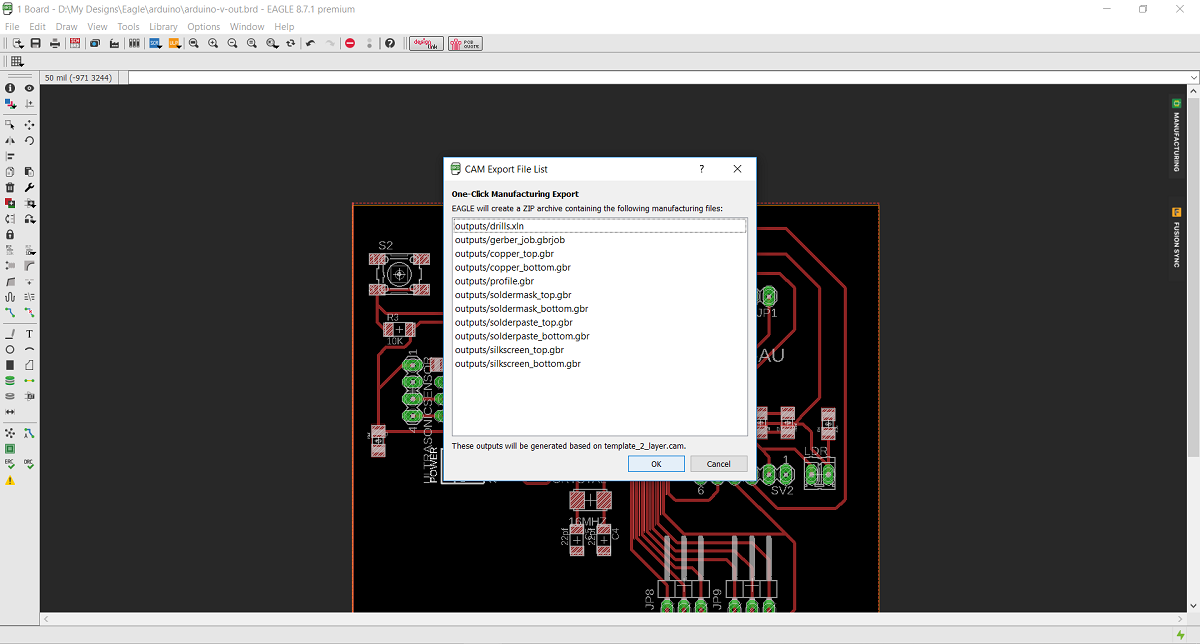
And this is the Gerber and Eexellon files that I will get in a zip file .
After I extracted the zip file I opened flat cam, from file I chose open gerber file wich mean I opened the file that contain the traces and the board ouside cut, then I chose open Exellon file which mean I Opened the file that contain the holes that I want to drill.
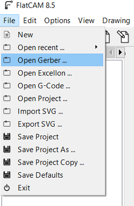
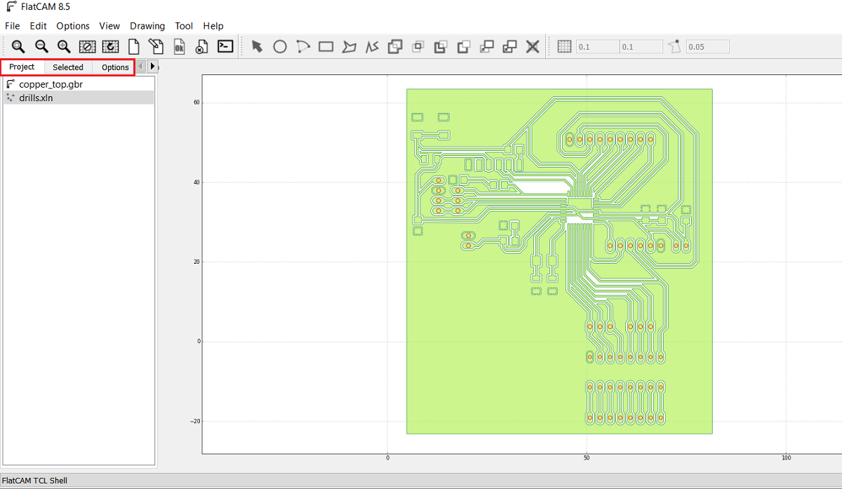
The first thing I did Is to open flat cam software then from file menue I chose open Gerber
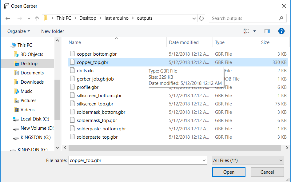
Then I selected cupper top in order to make the tool path for inside cut for the traces by 0.2 solid carbide end mill and the outside cut by 0.79 flat endmill
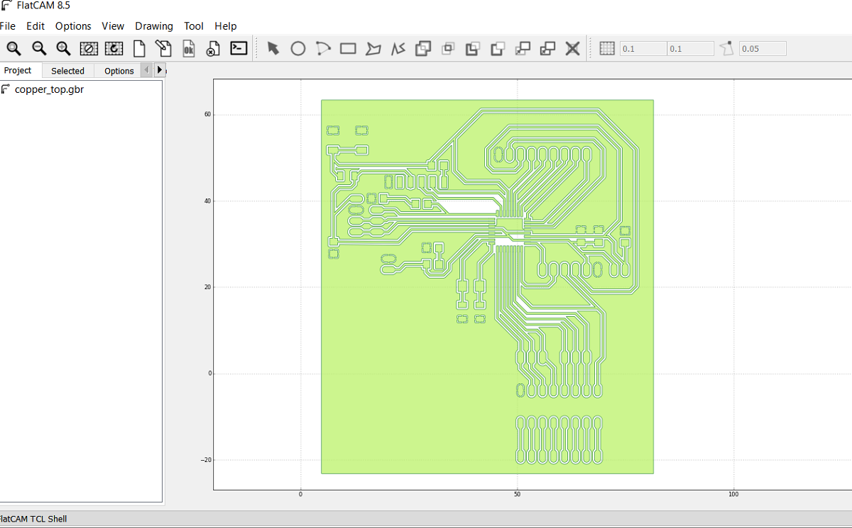
After I opened the selected file this is how its look like
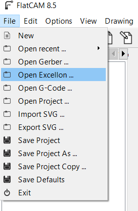
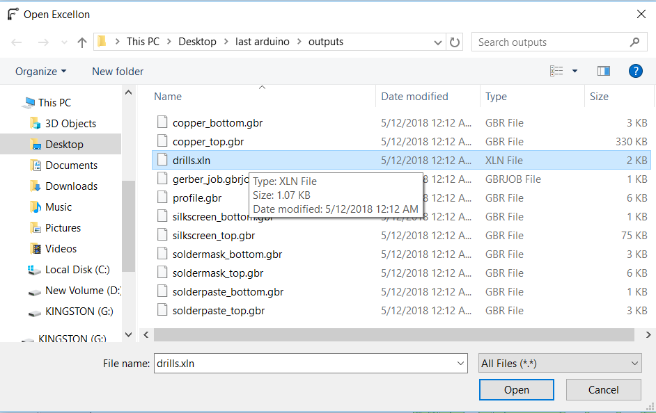
The second step is to open the Exellon file
And this is the Exellon file shown as drill.xln
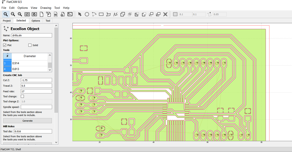
After I opened the Exelon file this is the red lines as shown for the holes
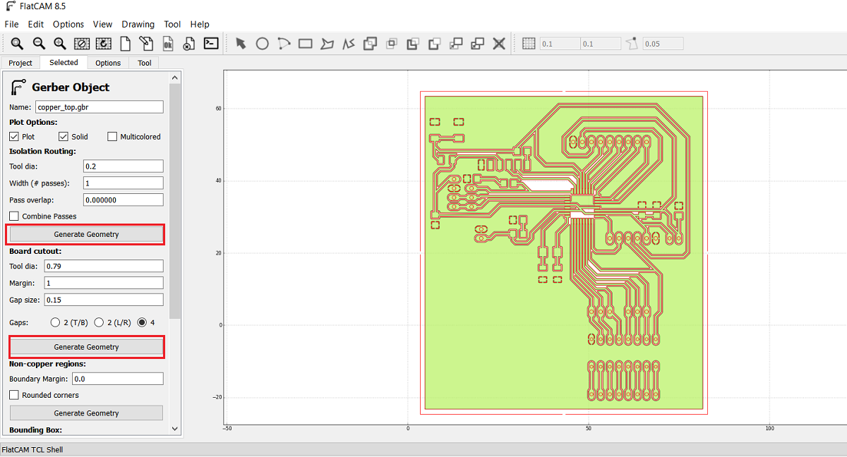
As shown in the above picture I got two jobs the first is for the inside and outside cut and the second one is for the drilling so I selected the cupper-top.gbr and then I went from project menue to select menue which in I can select the cutting variables, here I select the tool diameter of 0.2mm and the number of passes of 1 and the overlap is zero then i pressed generate geometry after this you can see the generated path for the inside cut and I did the same for board cut out and I generated the geometry as shown
Now after I finished cupper-top I went to project menue and I selected drill.xln so the main reason that forced me to learn and use flat cam instade of fabmodules is the drilling part as shown here I select all the holes diameters in this job so the 0.79 mm endmill will make all the holes but in fabmodules you have to make all the holes by black color in paint and then you can open the picture in fabmodule so using flat cam im more easy and professional
Here I put the cutting variables as shown
Now after I generated the insde, outside and drills files I got the CNC files so I opend each file.
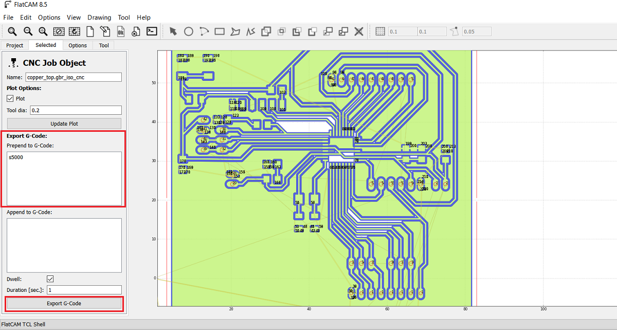
In order to set the spendle speed I type s5000 in the exported G code this is mean the RPM is 5000 and its the maximum spindle speed in tormach PCNC 1100 and then I exported the G code as .nc
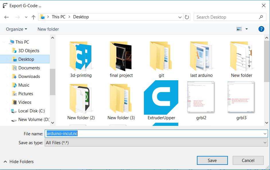
I repeated the process for the out and drill cnc files.
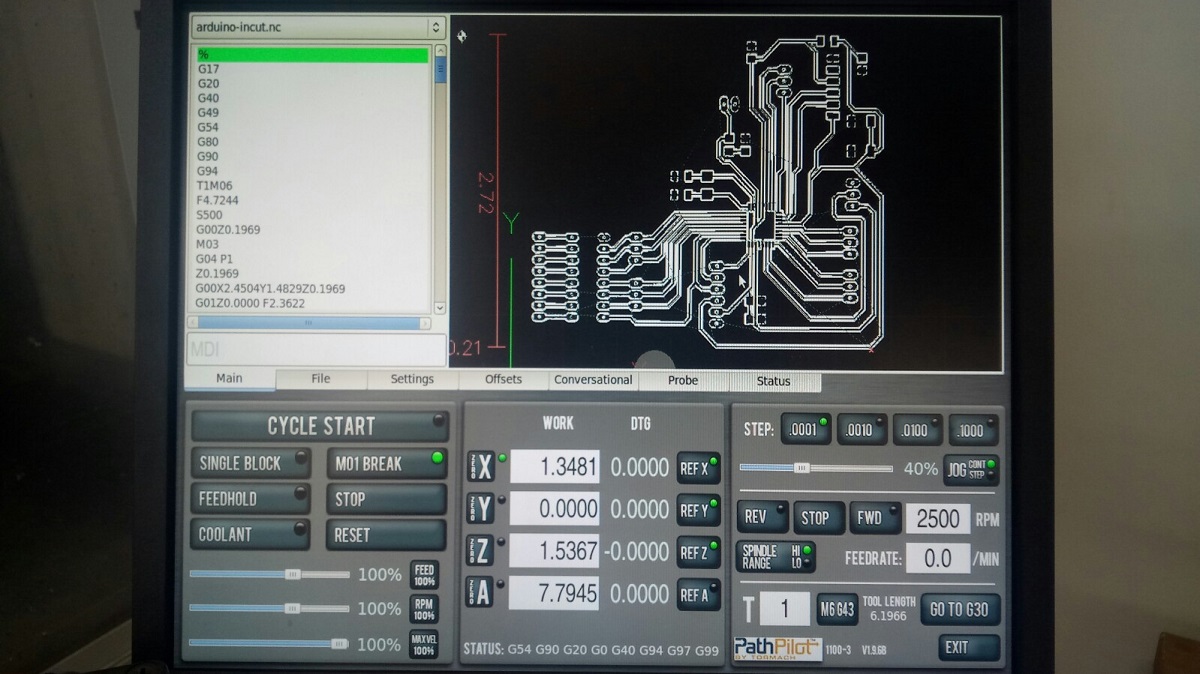
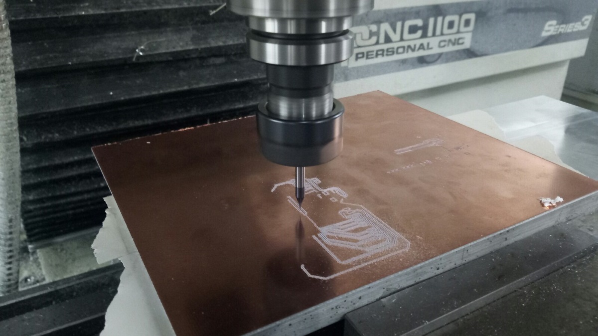
After I got the nc files I put then in a usb and the machine that I used is Tormach pcnc 1100 then I opened the file as shown
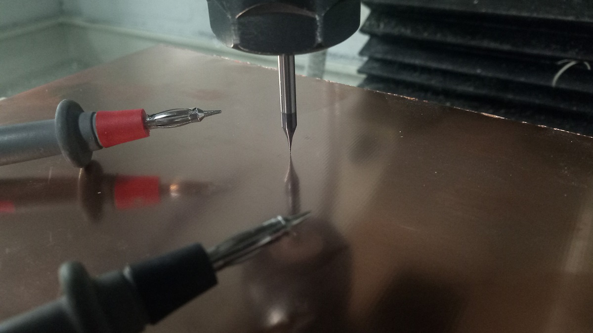
I used the Avometer to zero the z axis and thin I started the milling
And this is my board after soldering :D
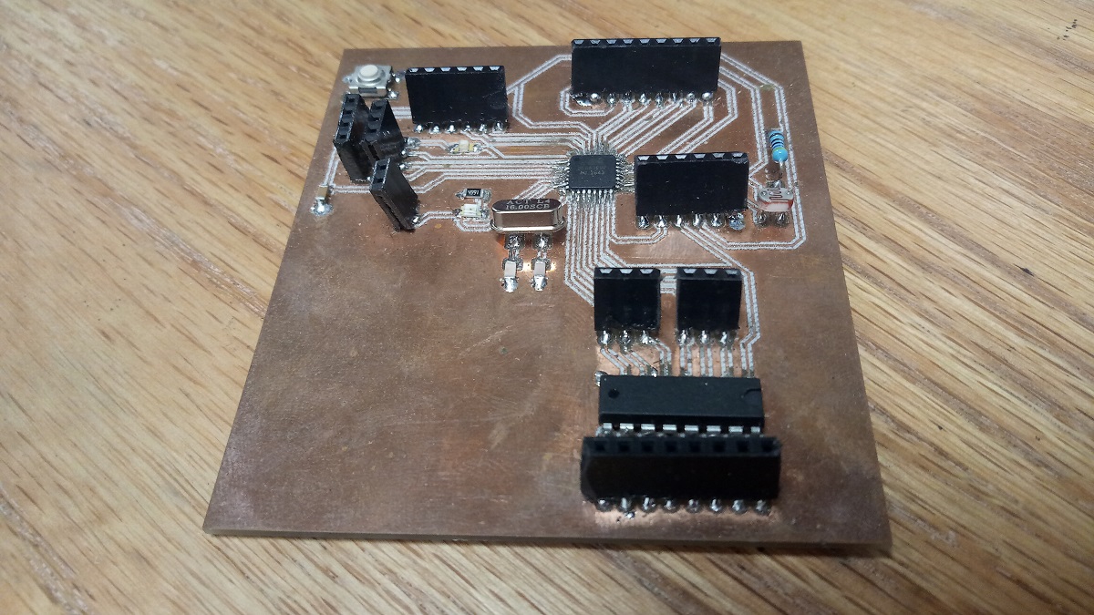
And this is the components that I used :
1.Atmega 328p is the IC.
2.Two capacitors 100nf.
3.LDR sensor.
3.Crystal 16MHz
4.Two capacitors 22pf
5.One capactor 10nf
6.One capacitor 1nf
7.Two resistors 499 ohm
8.One resistor 10k ohm
9.One resistor 4.7k ohm
10.Pin headers
11.RST buton
12.ULN 2003AN
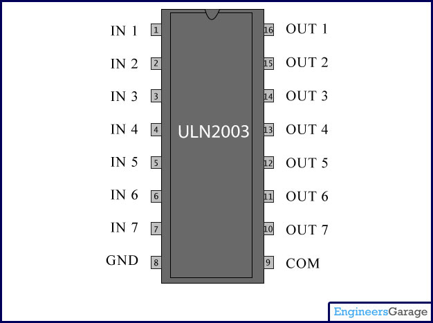
The most important component which I have integrated is ULN2003, which is an array of seven NPN Darlington transistors and here is the features of it :
• 500-mA-Rated Collector Current (Single Output)
• High-Voltage Outputs: 50 V
• Output Clamp Diodes
• Inputs Compatible With Various Types of Logic
• Relay-Driver Applications
Now I want to controll Stepper motor NEMA 17 which is a 6 wires unipolar stepper also it can be turned in to bipolar but I used it in unipolar mode by using the centers wires and here is the features of it
Four phase stepper motor
Rating: 12V @ 0.4A per phase
Step angle: 1.8 ± 5%
Detent Torque: 250 g-cm
Holding Torque: 3.2 kg-cm
Inductance per phase: 28 ± 20% mH
Resistance per phase: 30 ± 10% Ω
Speed: 100-600 RPM range
Mounting hole space: 1.22"
Mounting holes: 0.10"
Shaft diameter: 0.20"
Shaft length: 0.95"
Motor diameter: 1.67"
Motor depth: 1.89"
Weight: 0.60 lbs.
Screw Mount Dimensions: M3
Here is the code for the stepper
In order to controll the motor in unipolat mode I connected the centers wires which they are the white and yallow with the power sorce pin for ULN2003 which is com 9 also I connected the 12 v power with it for the GND of the power supply I connected it with the board GND also I take 5 V for the board from the power supply
Then I connected the phases wires RED, BLUE, BLACK, AND GREEN with OUT COM 2, 3, 4 and 5 respectivly
Proof
This is my board schematic and board design
This is my board outside cut and inside cut
This is my dc motor codes code1, code2 and code3
This is arduino and leds code
This is the 4 wires stepper Code
This is the second edited Board schematic and Board layout
This is the NEMA 17 6 wires code