Computer-Controlled Cutting Week
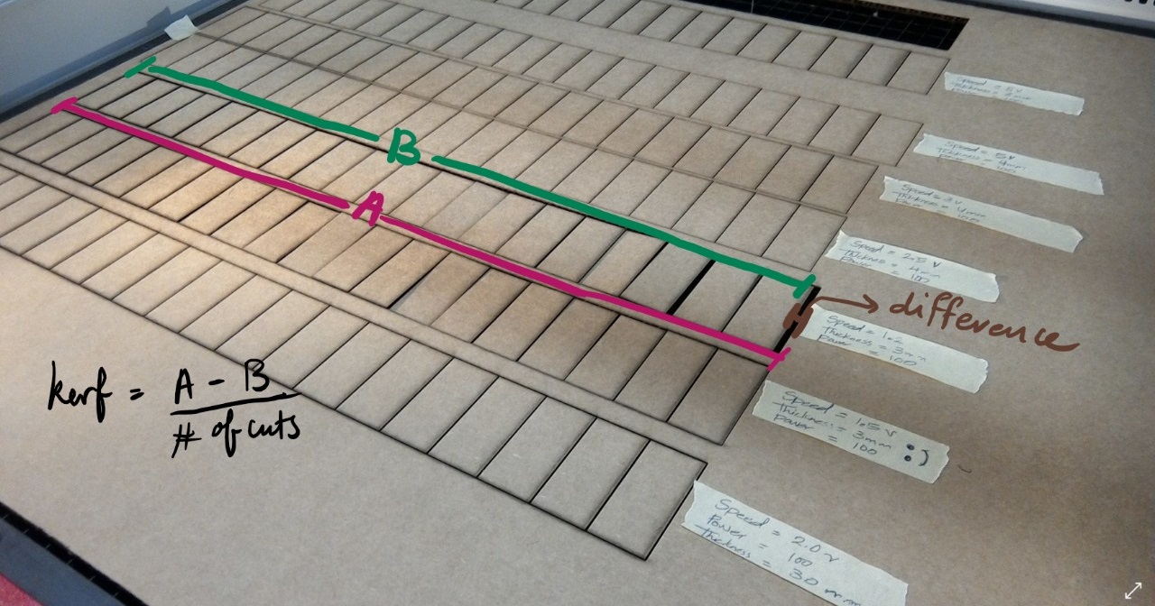
This week's assignment is to use the vinyl cutter and make a press fit kit with the laser cutter. A group assignment was to find the kerf of the material and account for it in our parametric design.
Lasercutting
This week was different from previous weeks, cause we had a group assignment. The assignment is to calculate the kerf for different materials. I chose to test the kerf for the cardboard. The thickness I chose was 4mm.
I tested so many settings, most didn't cut the cardboard all the way through. I however found 2 settings that made perfect cuts which are:
- Setting #1: Power: 100, Frequency: 1000, Speed: 1.2
- Setting #2: Power: 100, Frequency: 1000, Speed: 1.5
To distinguish between these two settings, I calculated the kerf for both of them, to do that, I sketched a rectangle, dimensions 20cm x 5cm, using  InkScape then I divided it into 20 equal rectangles, as seen below.
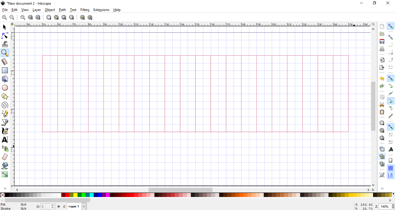
Then I cut it twice using the above 2 settings, the kerf for the first settings with speed 1.2 was 0.26 while the kerf for speed 1.5 was 0.3. Of course I'll choose the settings with the less kerf which was speed 1.2.
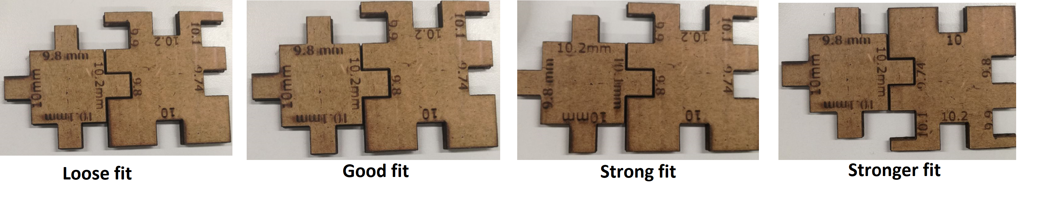
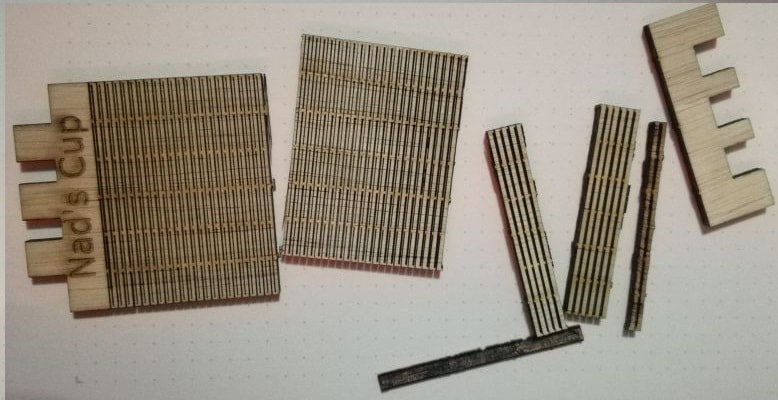
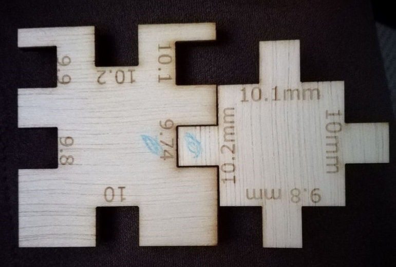
To make sure I got the kerf right, I designed the following and cut it.
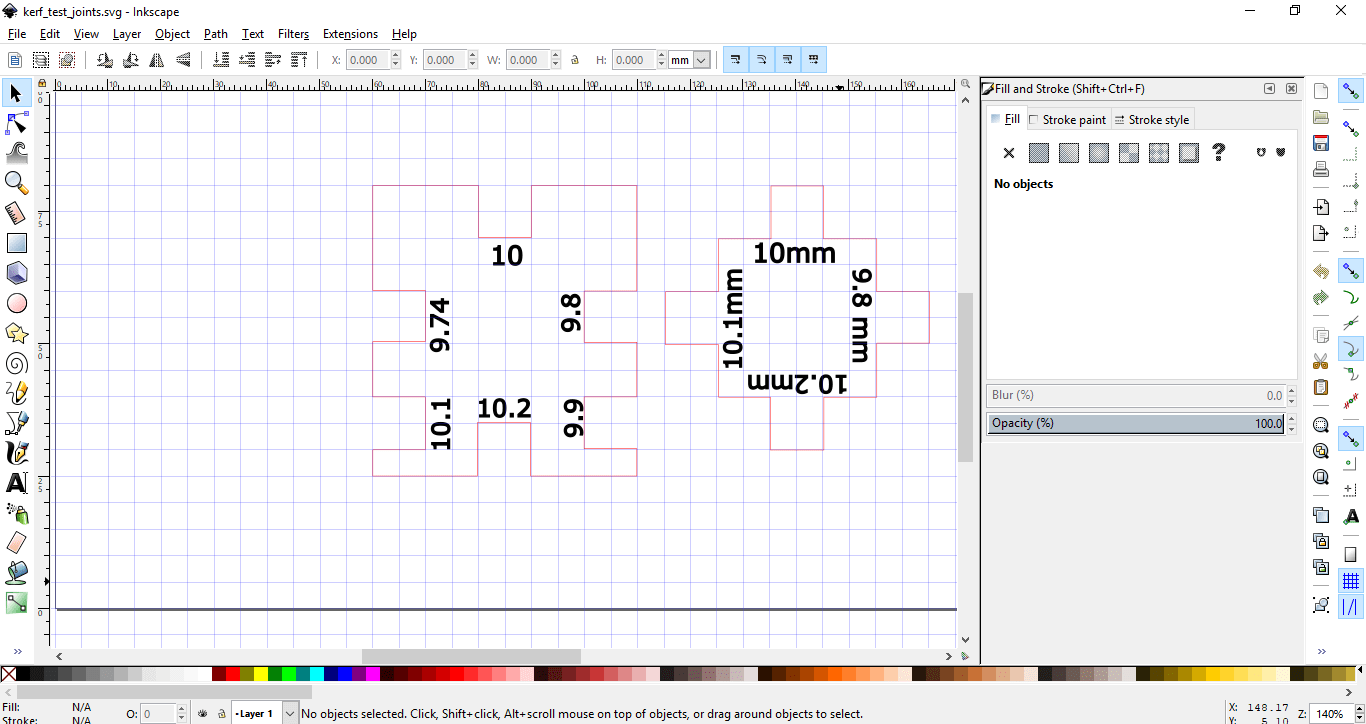
I found the best fit to be 10.2 mm with 9.7mm as seen below.
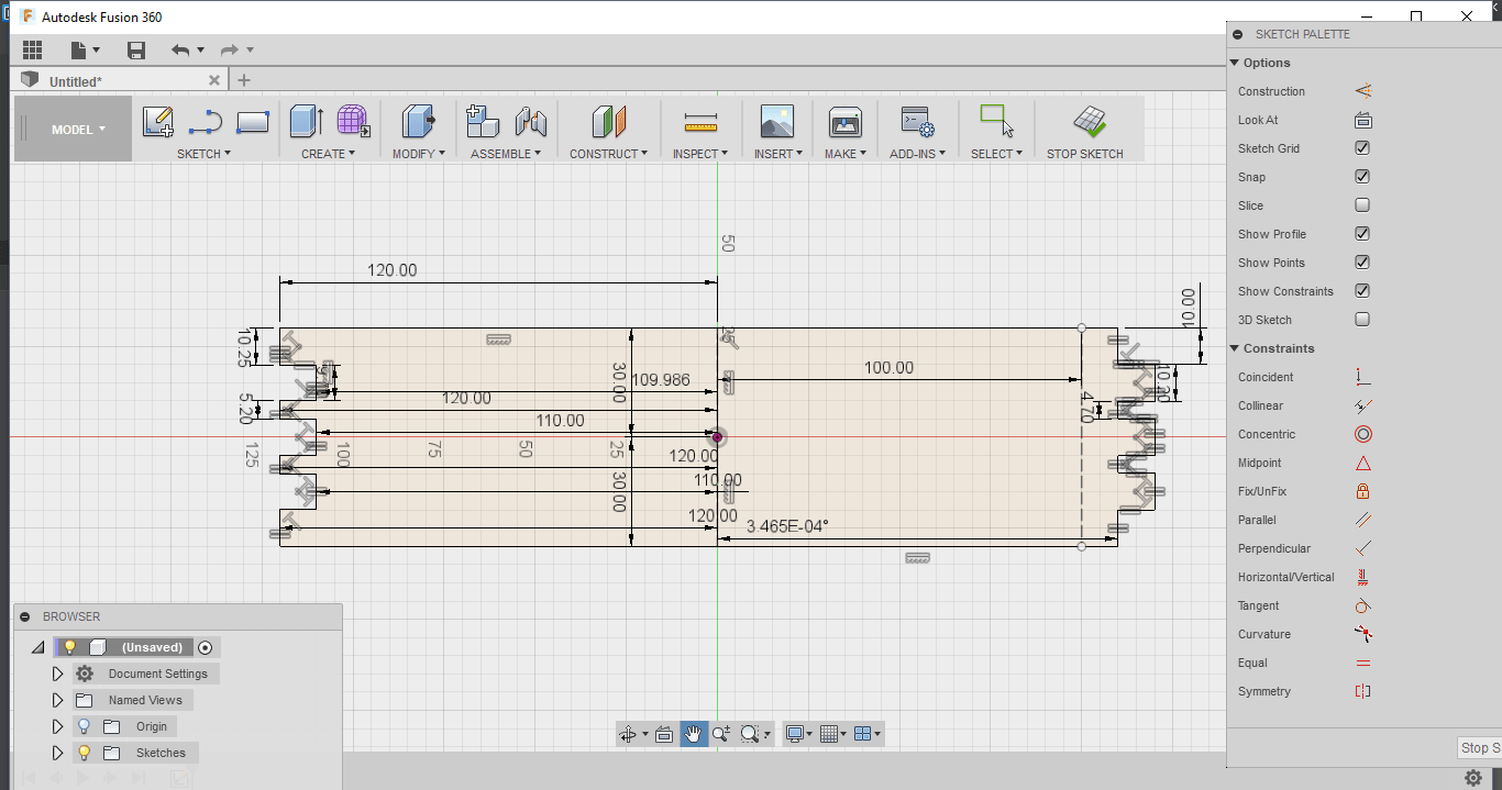
Now that I found the kerf that I need to account for it in my designs. I have to make a press-fit kit. I decided to design and lasercut a table. I used  Fusion 360 to do that.
I'm not much of an artist to say the least, so I'm quite happy with the below design.
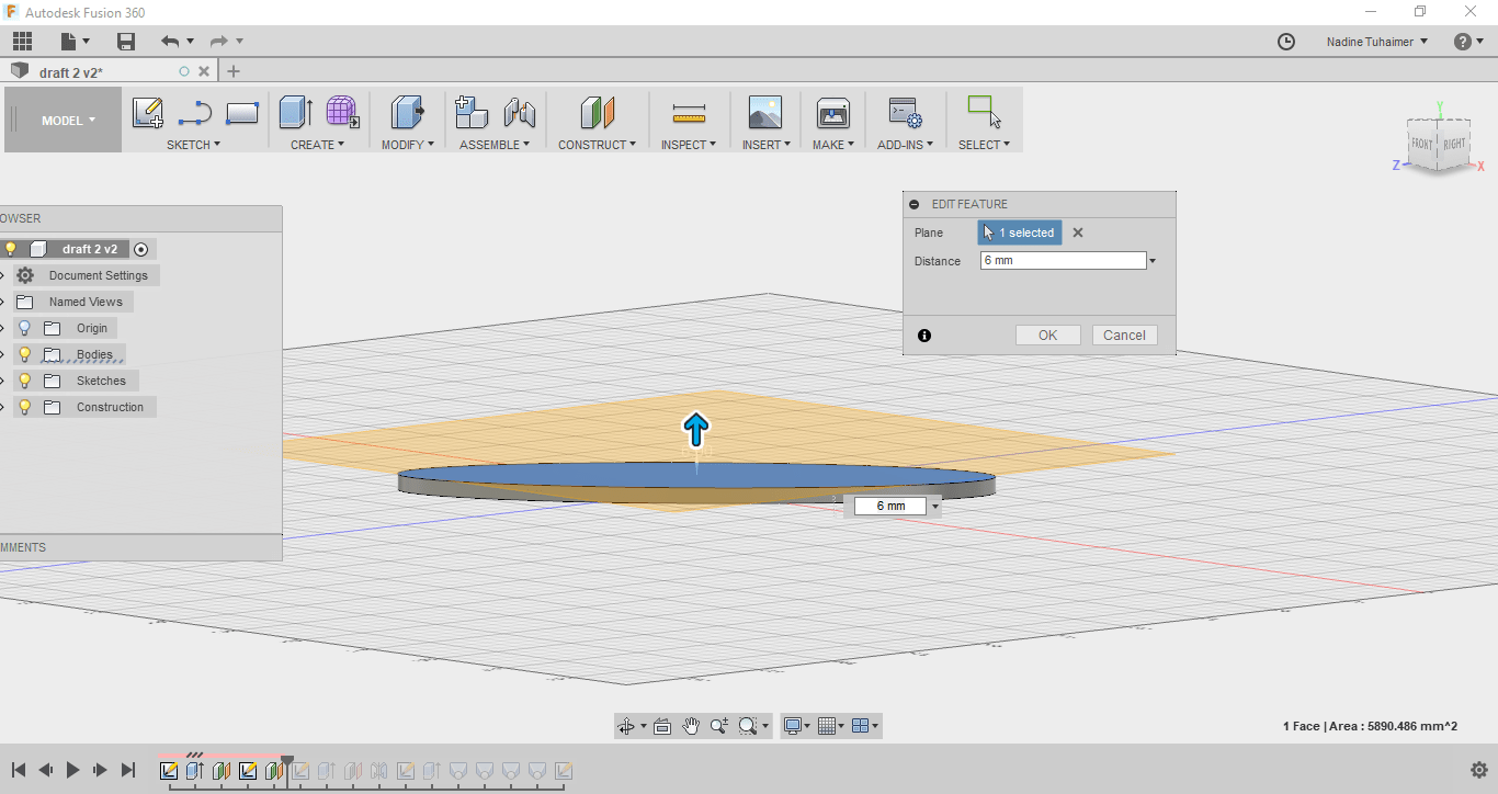
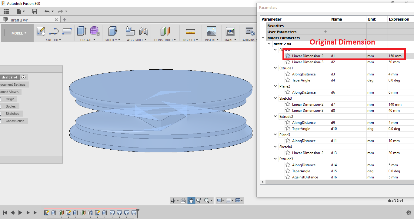
I designed this by sketching an elipse with height 150mm and width 50mm, then extruding it with thickness of 4mm and then constructing an offset plane with distance of 6mm.
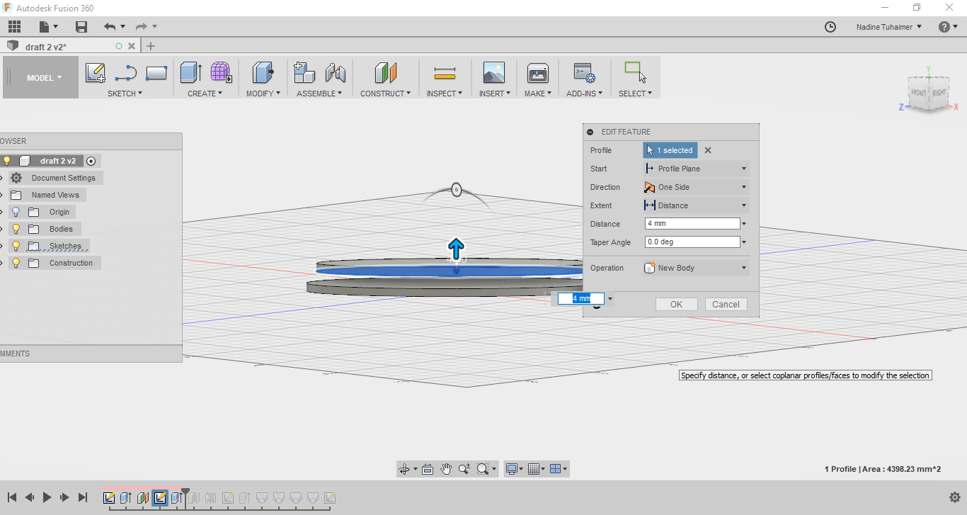
Then I sketched another elipse on the plane I constructed with height 140mm and width of 40mm then I extruded it giving it a thickness of 4mm.
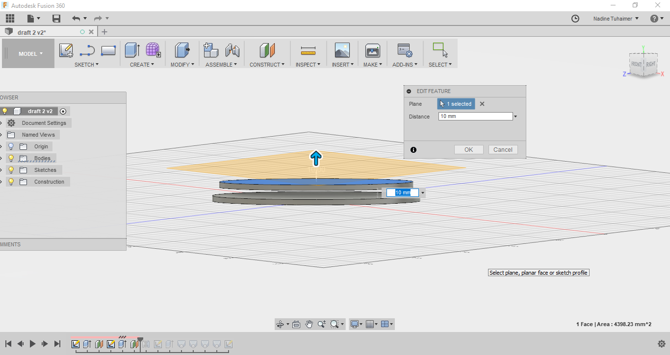
Then I constructed another offset plane but this time with the distance of 10mm.
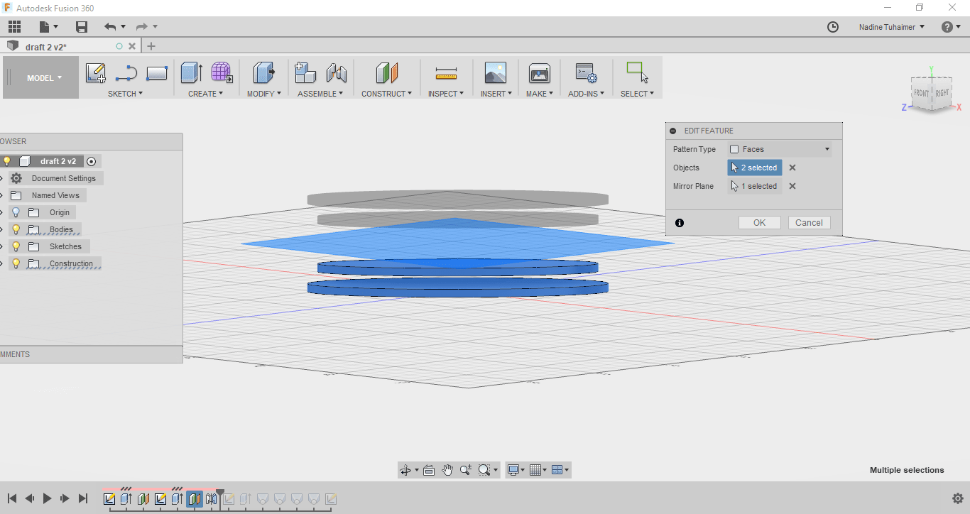
Then I mirrored the elipses I drew about the plane I constructed in the previous step, as seen below.
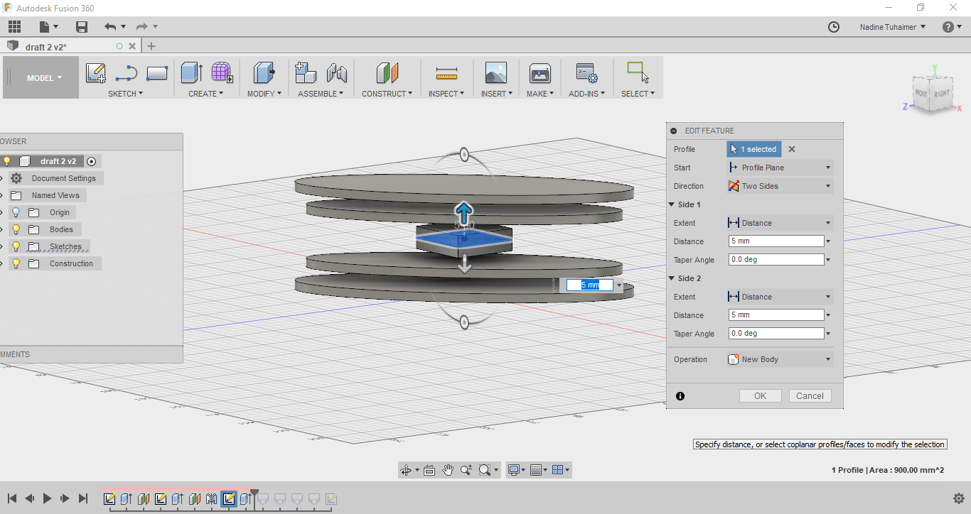
Then on that same plane, I drew a square with the dimensions of 30mm.
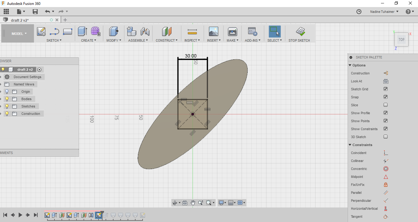
Then I extruded in 2 directions with thickness of 5mm as seen below.
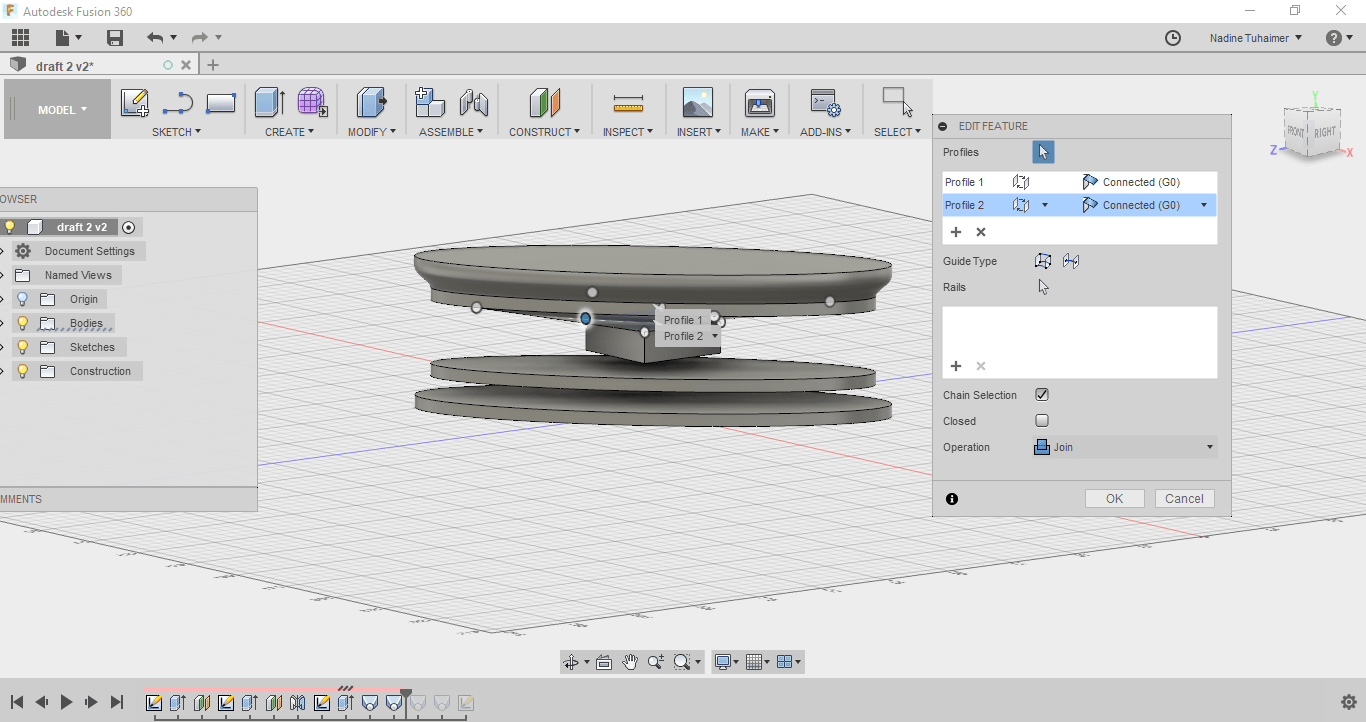
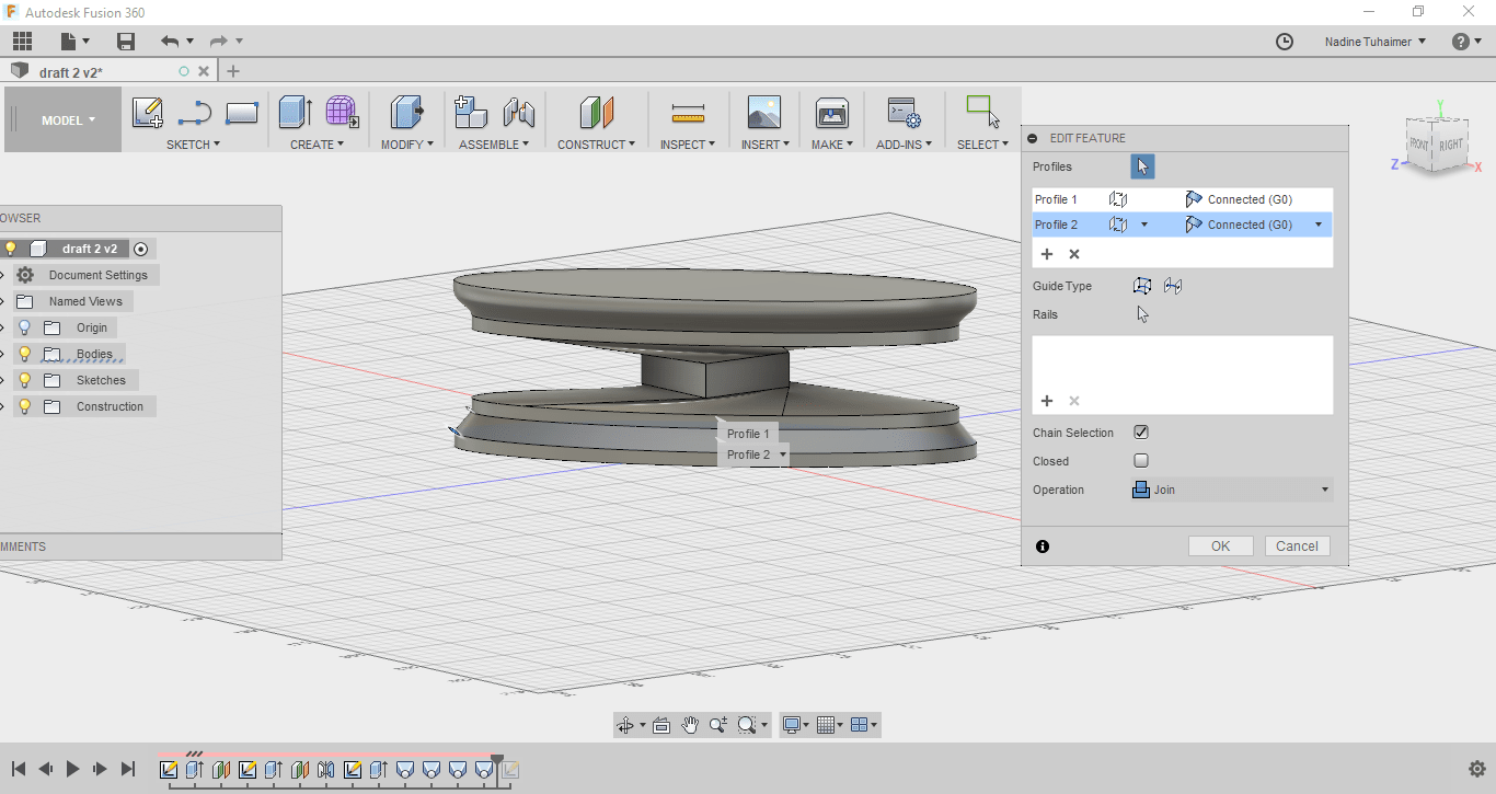
Then I started connecting these objects in different planes with each other using loft.
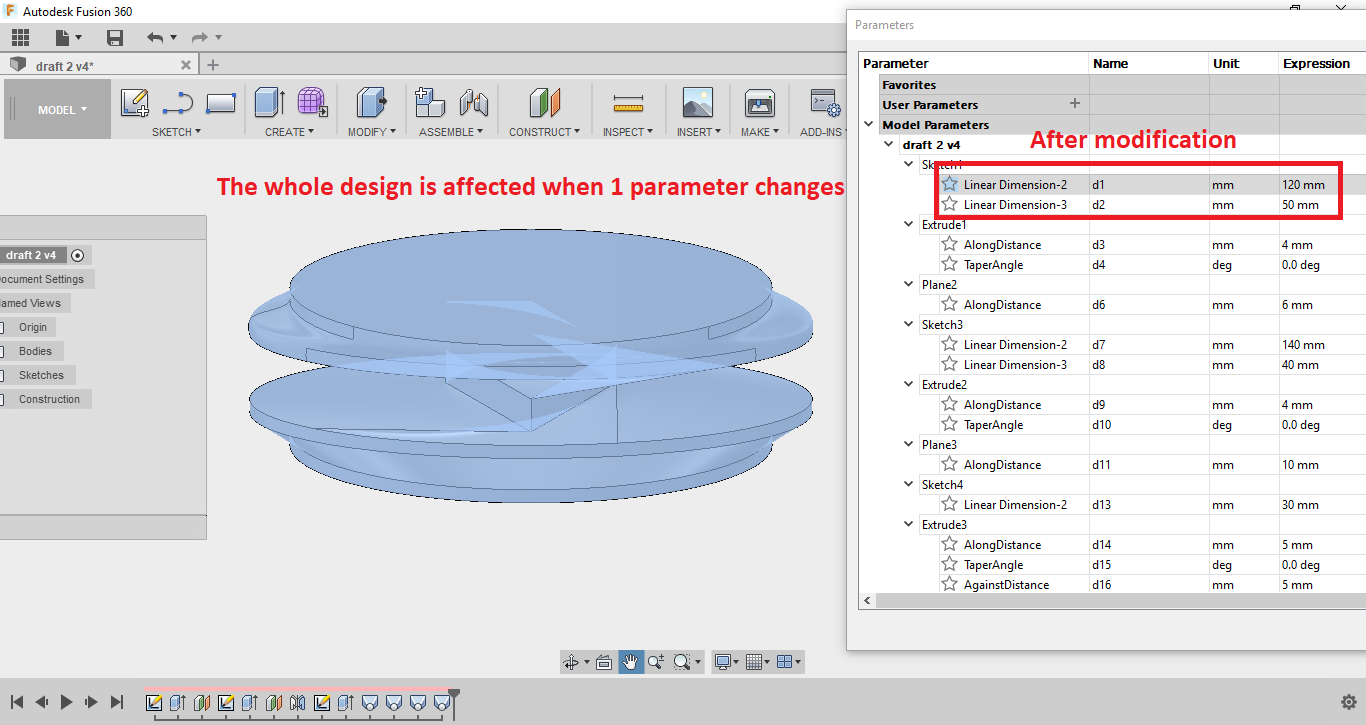
To make sure my design is parametric, I changed one parameter and the whole design changed based on it as seen below.
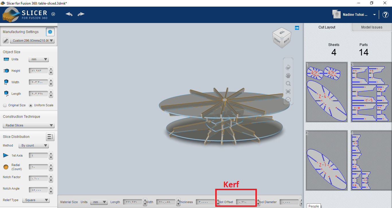
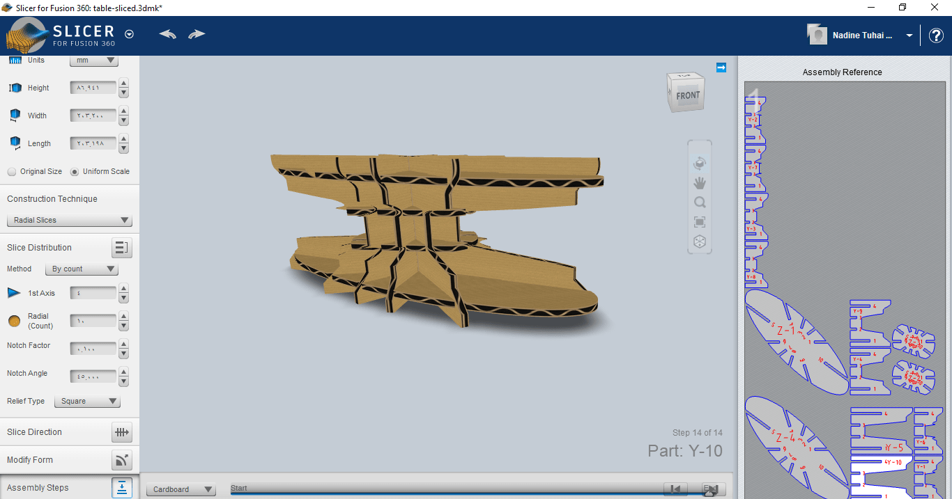
To lasercut this model, I have to slice it. I wanted to used 123D Make but the software was discontinued, so I asked my old friend Google and discovered there's a slicer for Fusion. I downloaded it and sent my design to it.
I chose Radial Slices as my construction technique then added the kerf of the cardboard in manufacturing settings in slot offset then exported it in pdf Format then I imported the pdf to inkscape and edited the colors of the edges to be red because our lasercutter has color mapping where red cuts and black engraves. I also edited the edges thickness to be hairline but in inkscape there is no hairline so I just used 0.1mm and it worked.
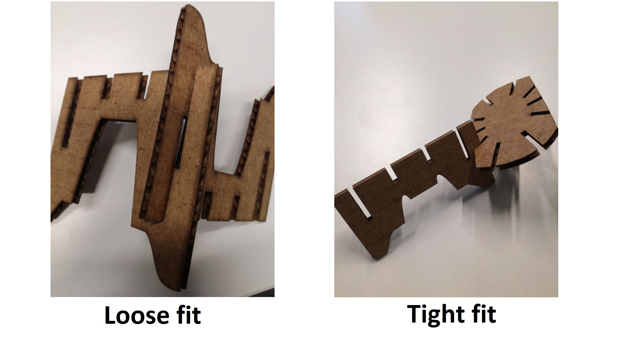
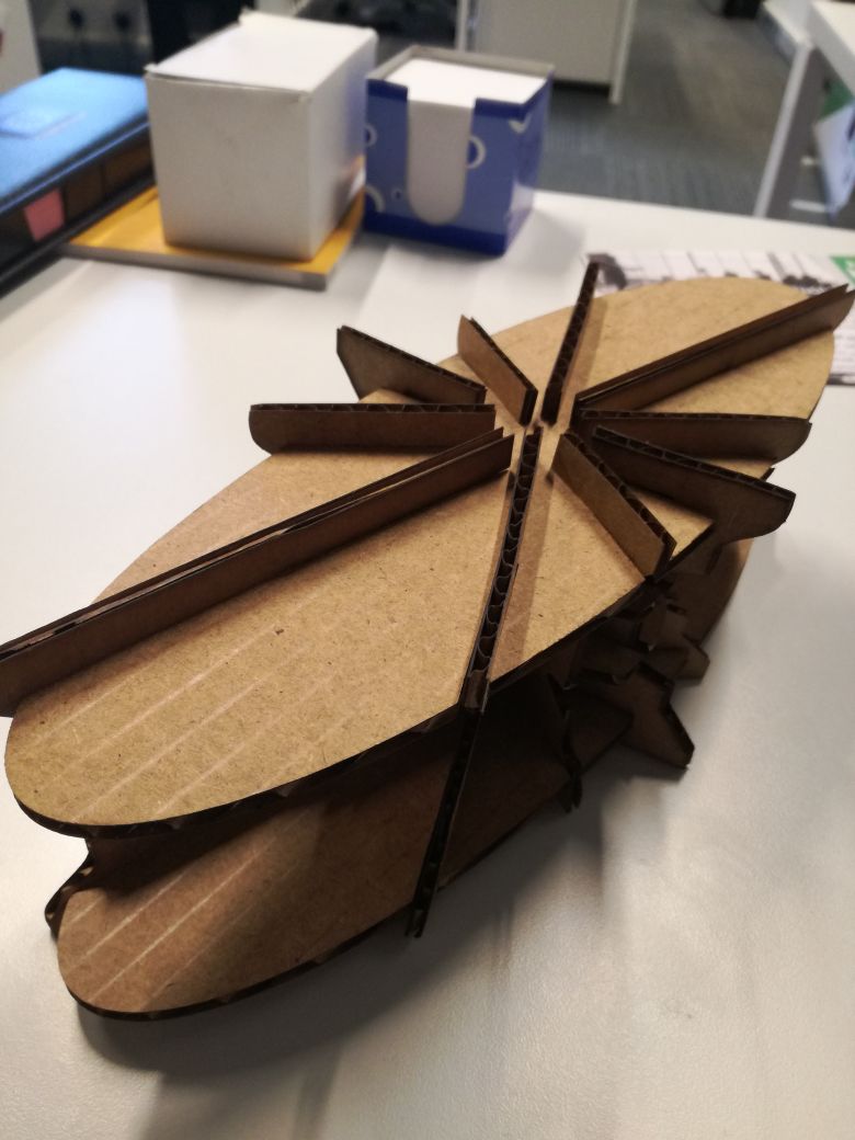
When I lasercut the parts, I noticed the joints were too tight which doesn't make sense, so I went back to slicer to check the settings and I noticed I accidentally put the thickness of the cardboard to 3mm not 4mm, so I edited that and lasercut another test but this time it was too loose. So I went back to measure the kerf again using my test and the strong fit had a 0.3mm difference while the stronger fit had a 0.5mm difference so I edited the kerf in the slicer to 0.4 (the average) and tested on only two parts and it was a really good fit so I used that.
The very cool thing about this slicer is that it also provides assembly steps in details.
I forgot to take a photo of the cut parts before assembly but the assembled table is seen below.
I wanted to try lasercutting a living hinge and I was sort of brainstorming when I ordered a cup of tea from the coffee place at the fablab, they gave it to me without a cup sleeve and it was too hot to carry so I decided to make a laser-cut wooden cup sleeve. So I designed it as seen below.
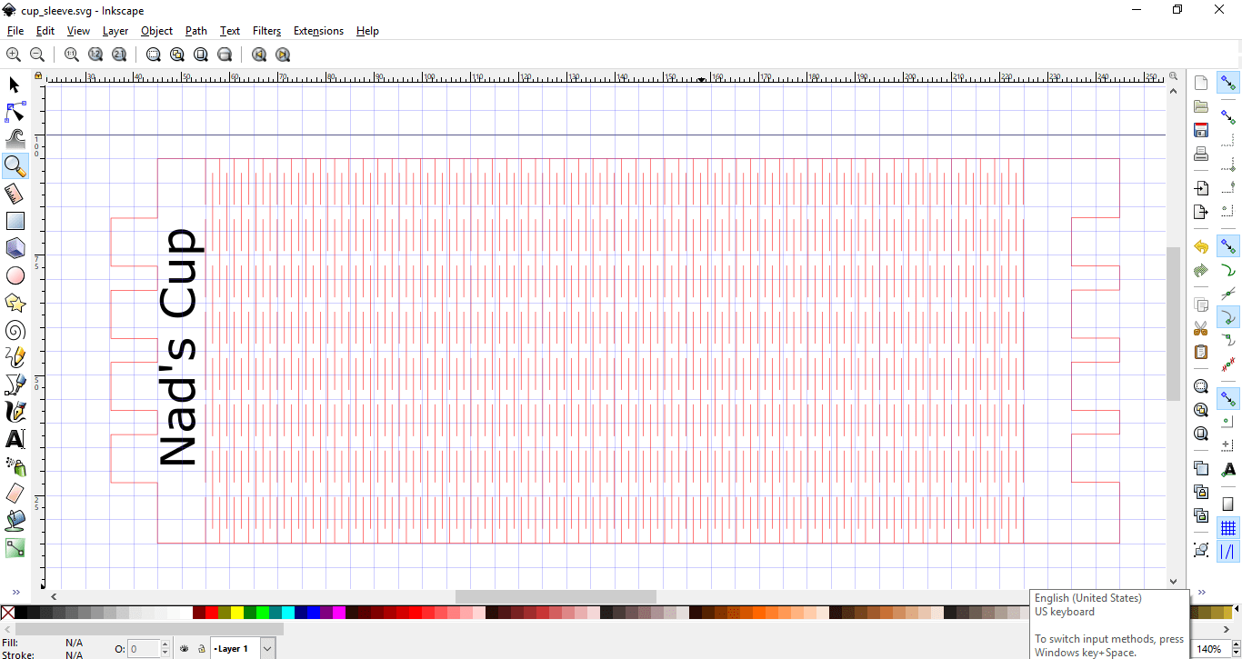
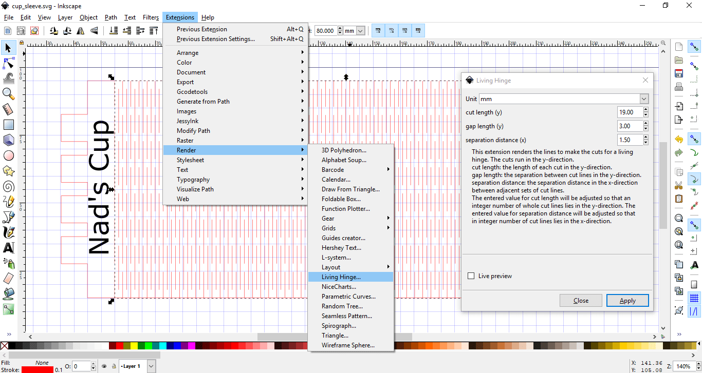
To have the plywood bend flexibly, I used a living hinge. I downloaded the inkscape extension for the living hinge and selected the inner rectangle and applied the living hinge to it as seen below.
As for the side joints, I used union and difference to create them.
I made my design in inkscape and made it parametric or so I thought. The thing with inkscape is when I use union and difference to create the tabs, the parametricity (don't know if that's even a word) goes away.
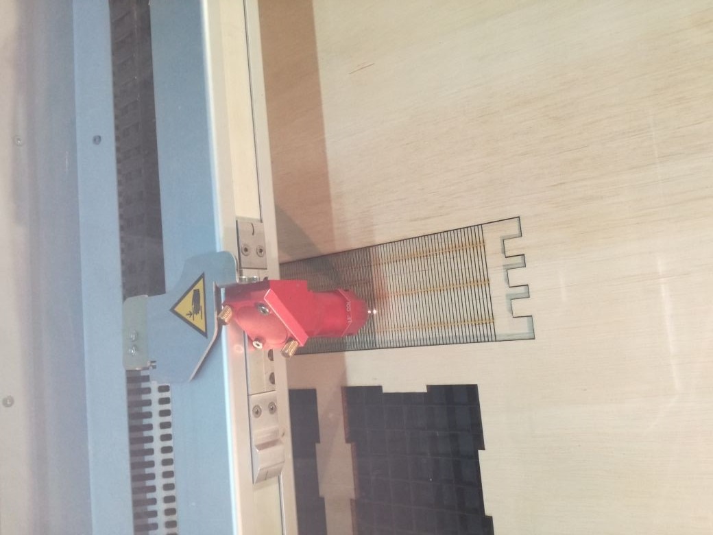
When it came to actually lasercutting, I found two problems, the first is that the joints don't fit (inkscape not keeping the parametric features is now becoming a problem) and that the lasercutter cut the outer surface first before cutting the hinges so the whole thing just fell apart the moment I took it out of the lasercutter, I solved that by cutting the inner lines first then the outer lines using vector cutting which calculates the best path to cut your design.
To solve the problems I faced, I designed the sleeve using Fusion 360, but my computer isn't too powerful to import the Fusion360 Patterns and use them, I tried and it kept freezing, so I designed the base in Fusion making it parametric then exported the sketch to DXF and imported it to inkscape to add the patterns just like before.
This time I wanted to make sure the joints fit, so I used the same joint test I did for cardboard on wood to know the best fit. Then I cut with Speed 0.6, Power 100 and Frequency 4000.
Vinyl Cutter
Vinyl cutting was also something we had to do in this week's assignment. I didn't know there were so many applications and things to be done using the vinyl cutter like flexible circuit boards for example, I wanted to test with that but I didn't find enough time to do that and my PCB design skills have unfortunately died due to lack of use, but I definitely will try something with circuit boards soon.
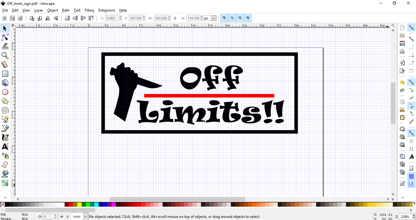
I decided to make a very intimidating "OFF LIMITS!!" sticker sign to stick to my laptop since my coworkers keep messing with it while I'm working on my assignments.
To design the sticker, I used inkscape. I wanted to add a hand drawing and the phrase Off Limits!! to it. While I was surfing my trusted BFF Google I found a drawing of a hand carrying a knife, and if that's not intimidating I don't know what is! So I imported the png photo to inkscape, added the phrase Off Limits!! and a red line to emphasize then added a border to the sticker as seen below.
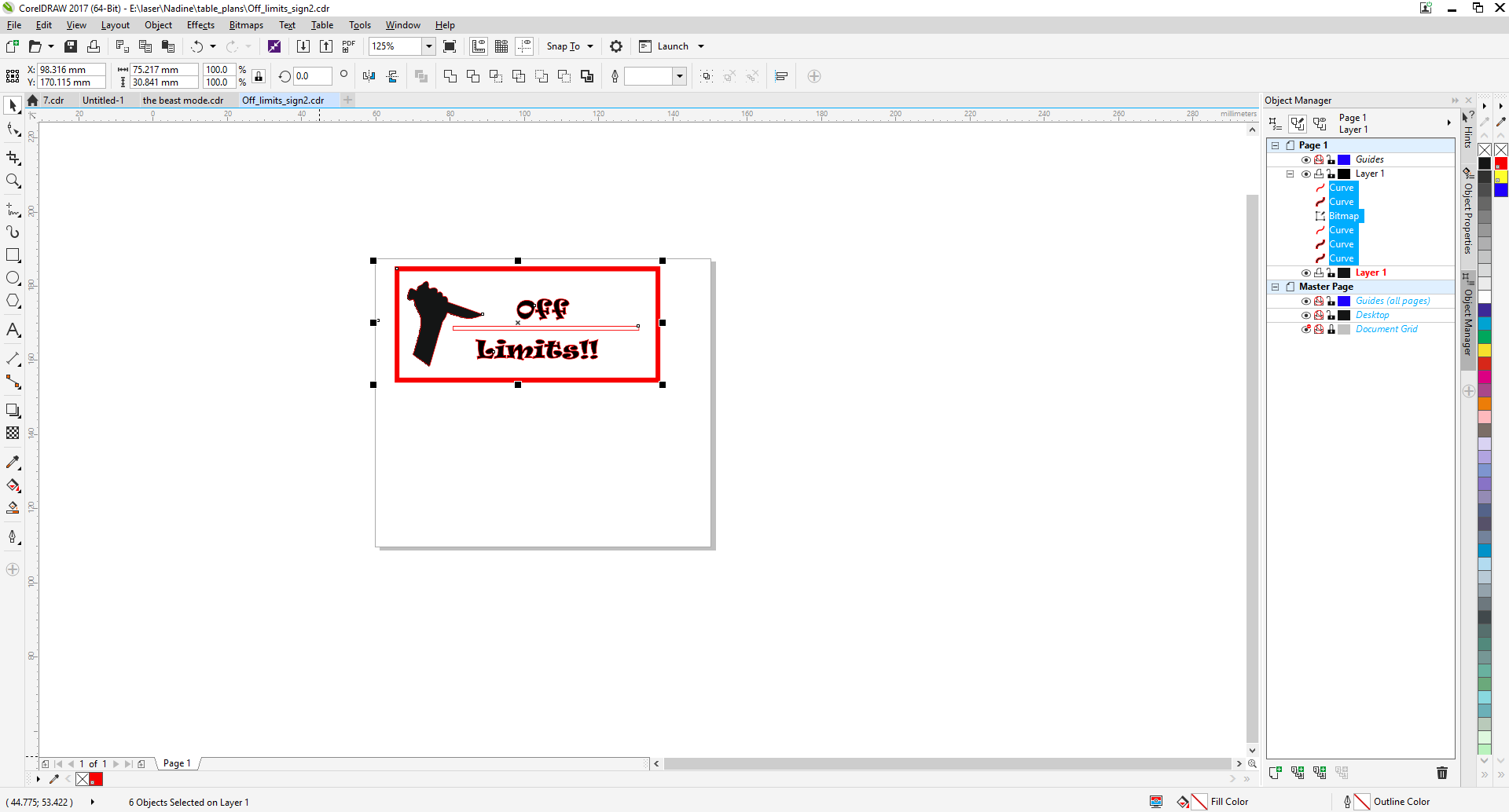
When I wanted to cut it, I choose red vinyl but I had to change the outer line of everything that will be cut to red cause that's the settings for our vinyl cutter. To do that I imported it to corelDraw and printed it from there.
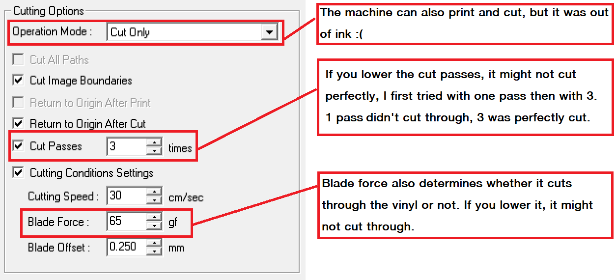
Our vinyl cutter is the VersaCAMM ® SP-300i, Large-Format Color Printer & Cutter. It's a professional vinyl cutter. At the first try I made the sticker in a small size with one pass of cutting but it didn't really cut well and I noticed that when I started peeling the sticker.
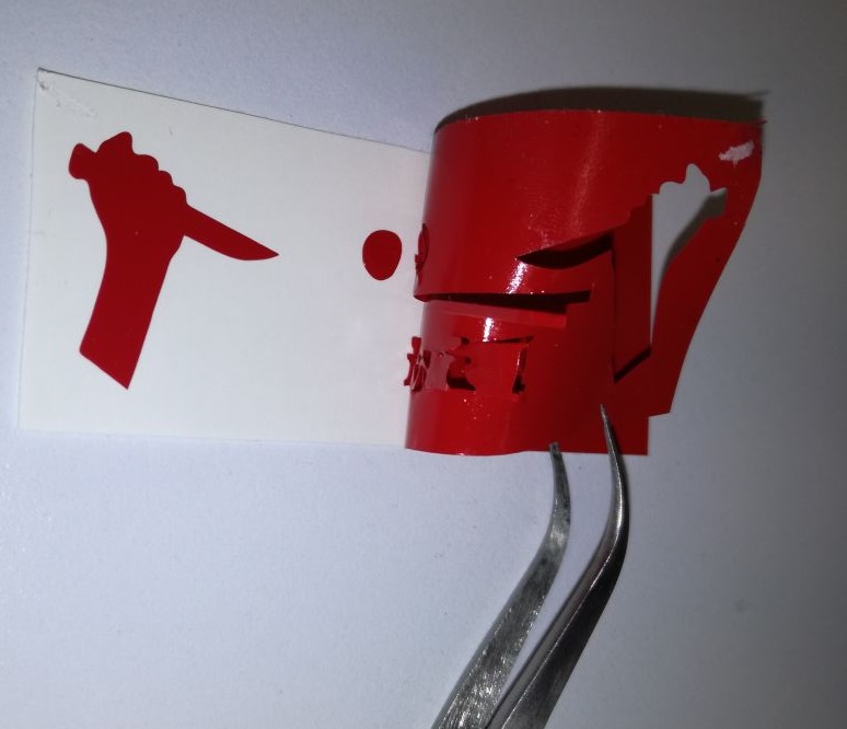
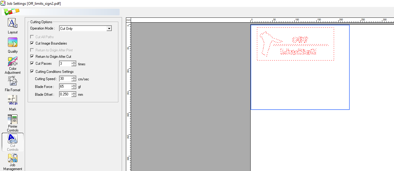
So to make my life easier, I repeated the cut this time with 3 cutting passes and I made sure I chose "return to origin" to make sure it cuts in the same way in all 3 passes and made the sticker bigger. The peeling process was way easier. The settings I used are shown below.
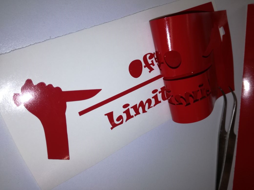
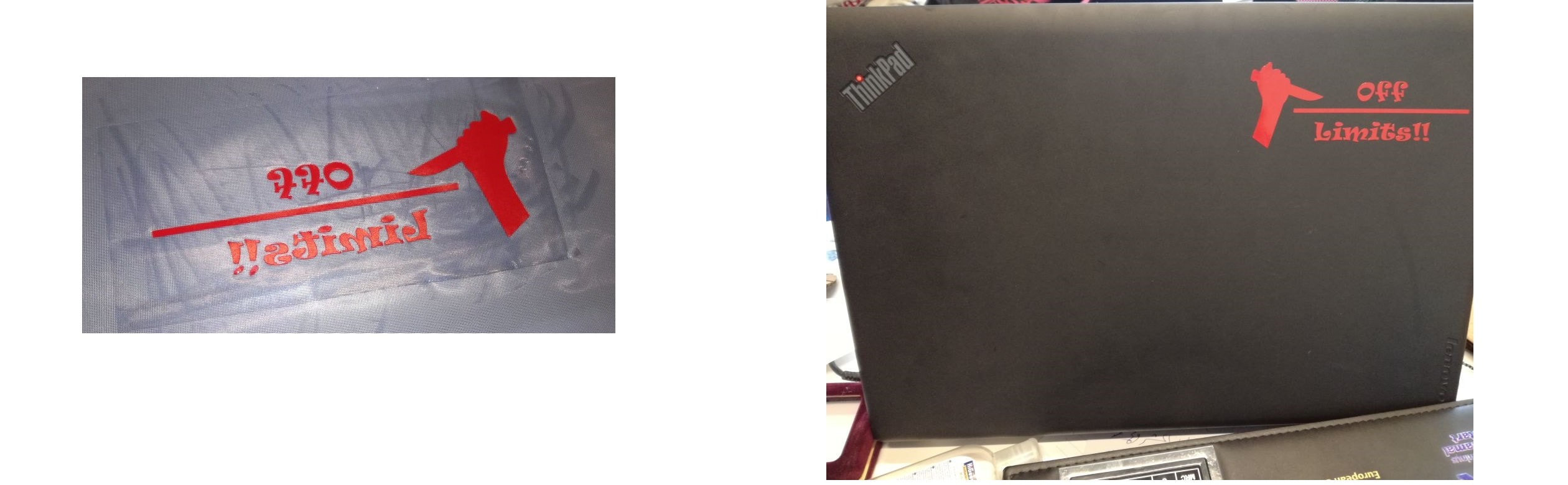
Then I removed the unecessary parts and moved the design to my laptop.
You can download my designs here:
