Computer Controlled Machining Week
Ever since I decided to take the Fab Academy, I was thinking about what I want to do for Make Something Big Week. I really wanted to do something that moves but we can't use nails or screws or any form of fixturing! Boy this is going to be tricky!
Designing the table
I decided to desing a table. I wanted to make a table with a special kind of design. So I decided to make one with a tree cut on it.
I used  Fusion 360 for my design.
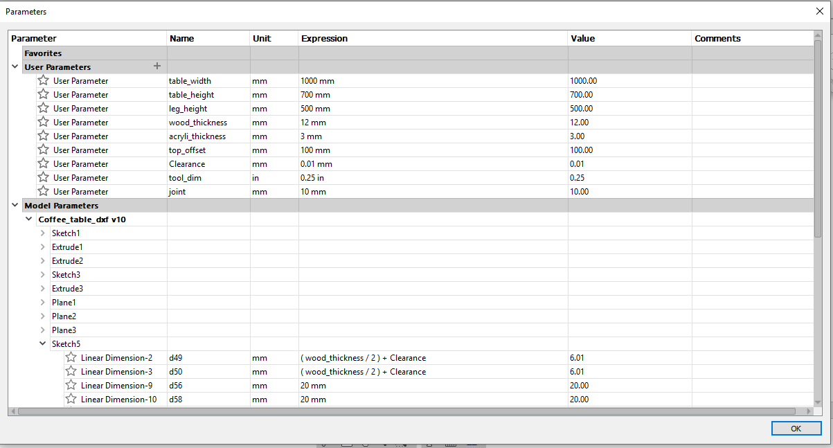
The first thing I did was add the user defined dimensions that I will use in my sketch. These include the wood thickness and the table width and height.
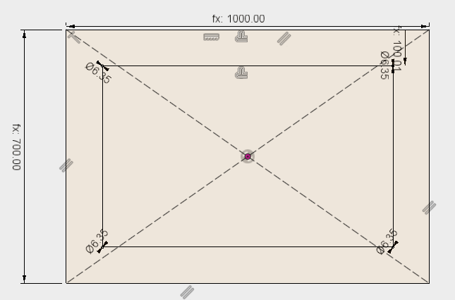
Then I sketched the table top and created an offset refrencing the dimensions I defined.
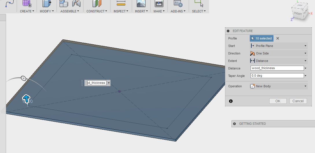
I extruded the table top to a thickness that is equal to the wood thickness.
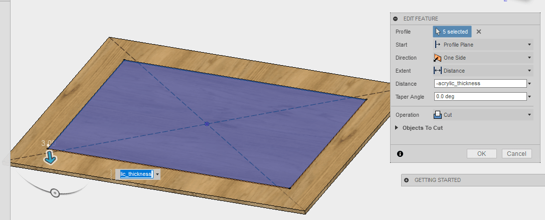
I want to add an acrylic top to the table so for that, I extruded the offset I created to a thickness equal to the acrylic thickness.
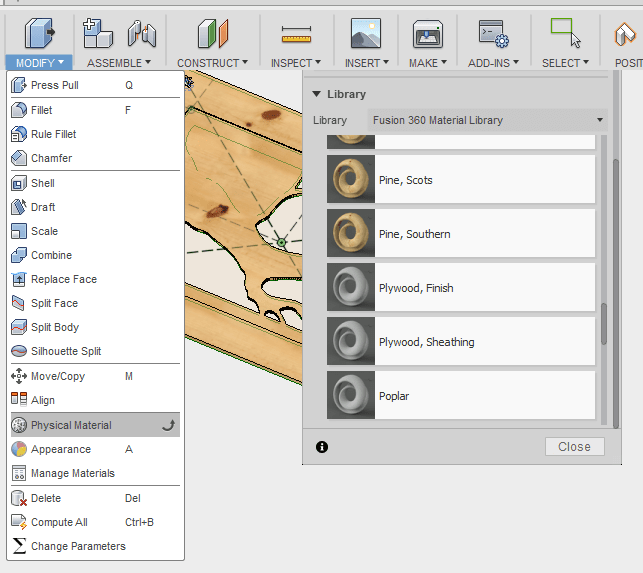
I also wanted to change the physical material to wood, just so I can visualize how it will really look.
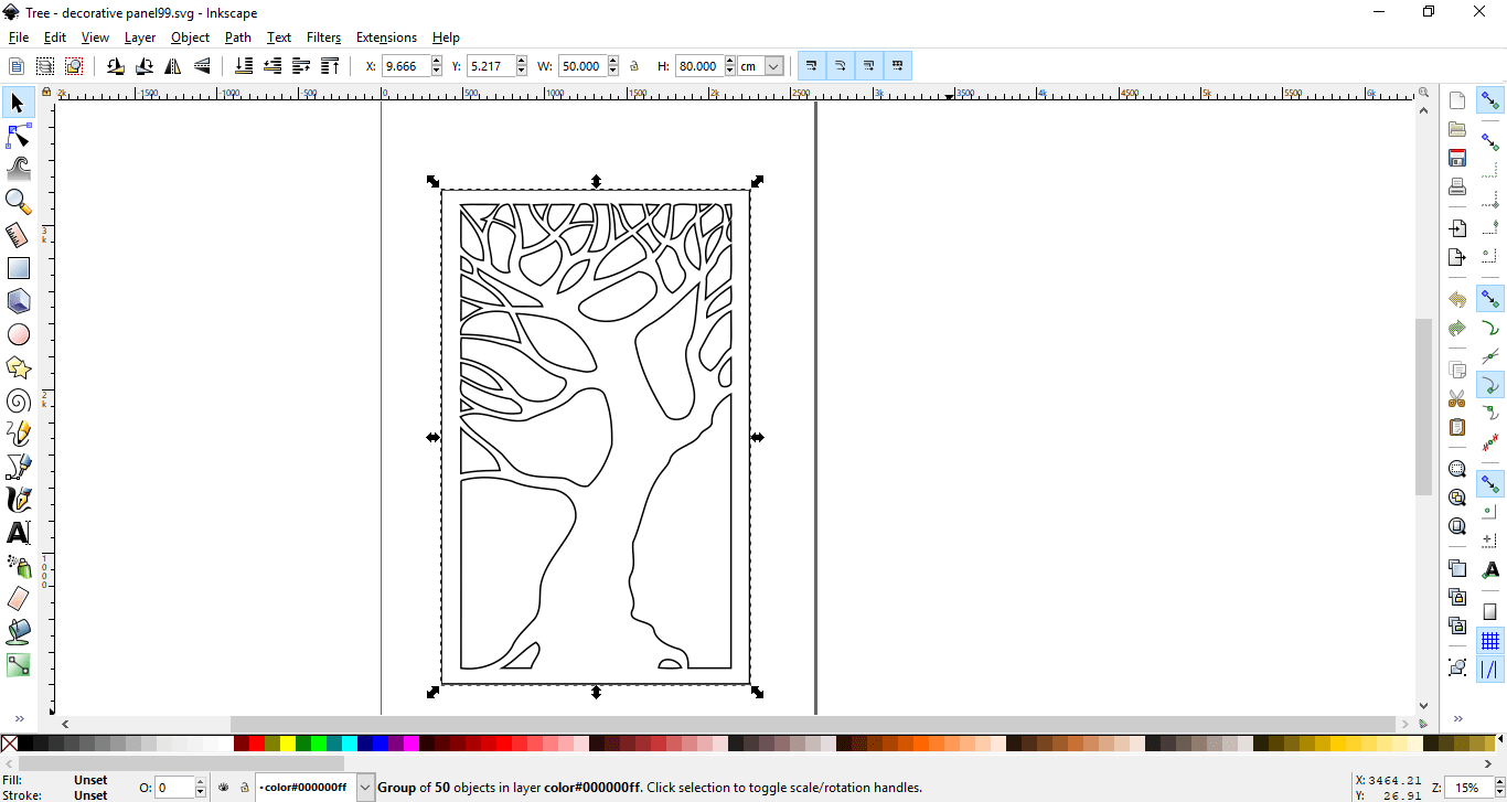
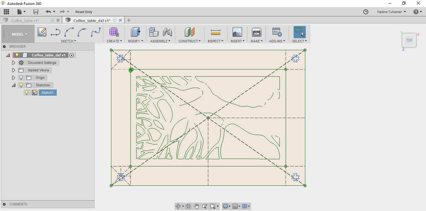
I then started browsing the internet to find cool DXF images that I can use and I stumbled across dxf1.com where I found a cool image of a tree and I thought it would look cool on the table top so I decided to use it.
I had to edit the scale of the image in inkscape to fit inside the offset rectangle I created.
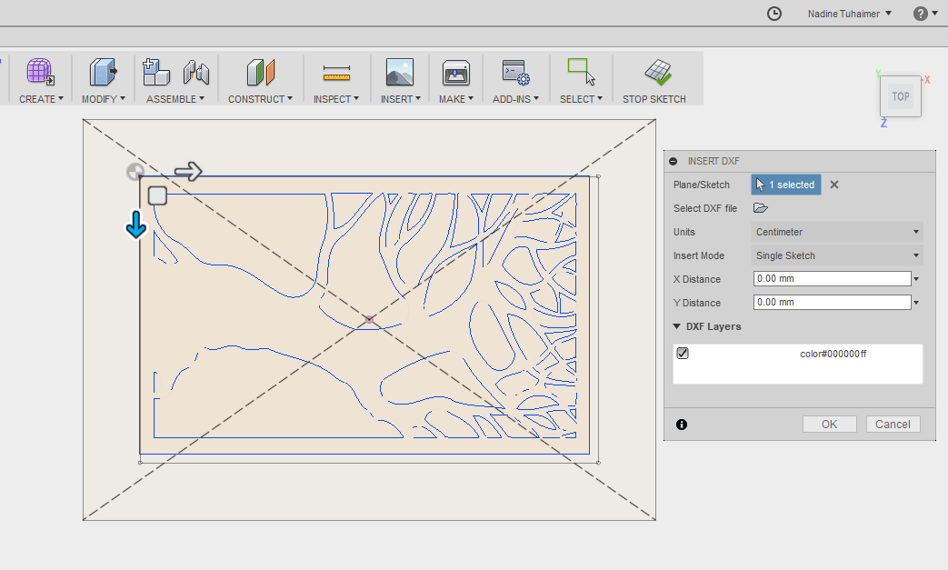
After that, I imported the dxf file in fusion and moved to be exactly on the offset rectangle where I want it to be.
After that I created the first joint where the legs of the table will fit.
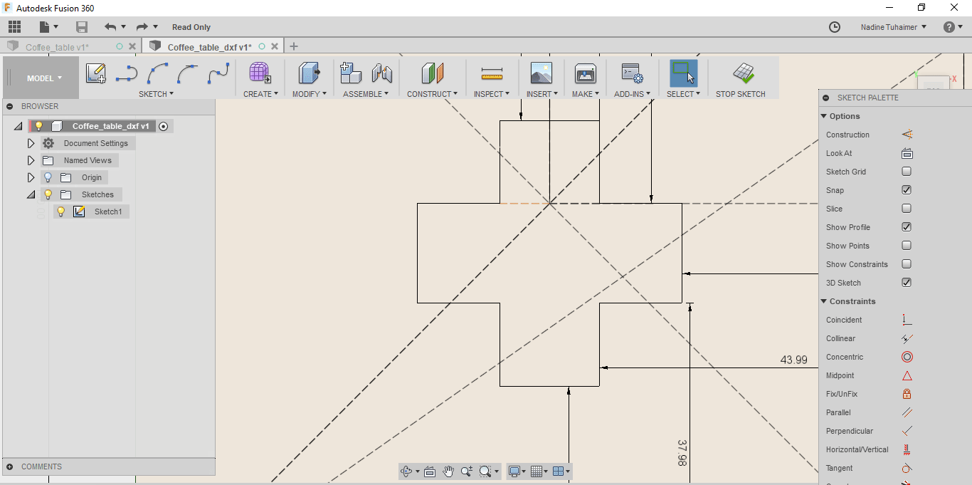
I added dog bone circles on the sides of the joint, these are to ensure you get a 90 degree angle, the diameter of the circle is 0.25"e; which is the same as the diameter of the drill bit I'll use.
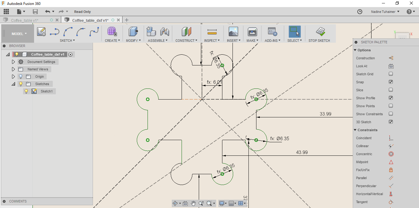
Instead of repeating the process, I used mirroring.
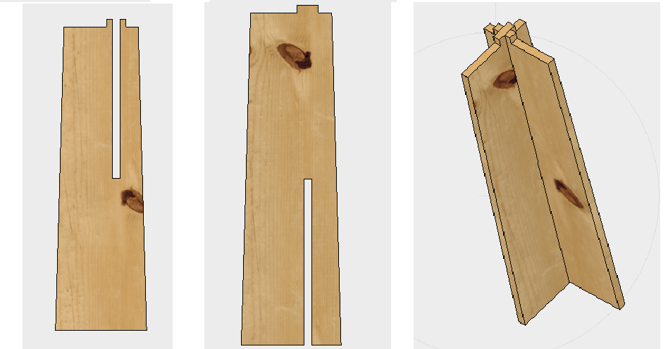
Next, I drew the first part of the leg. I wanted the leg to consist of two parts that are joined together to fit in the joint I created. I then extruded the first part to the thickness of the wood I will be using.
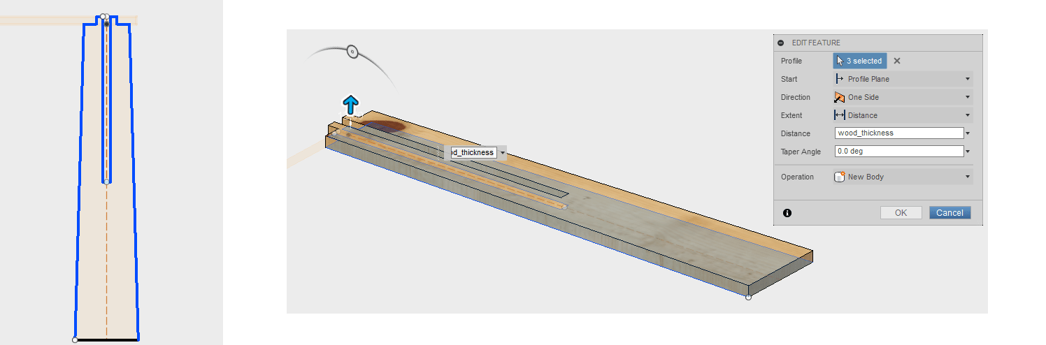
The leg was created using the user defined dimension called "leg_height=500mm". The subtraction equals half the length of the full leg.
I then sketched the second part that would fit into the first part creating the leg as seen below.
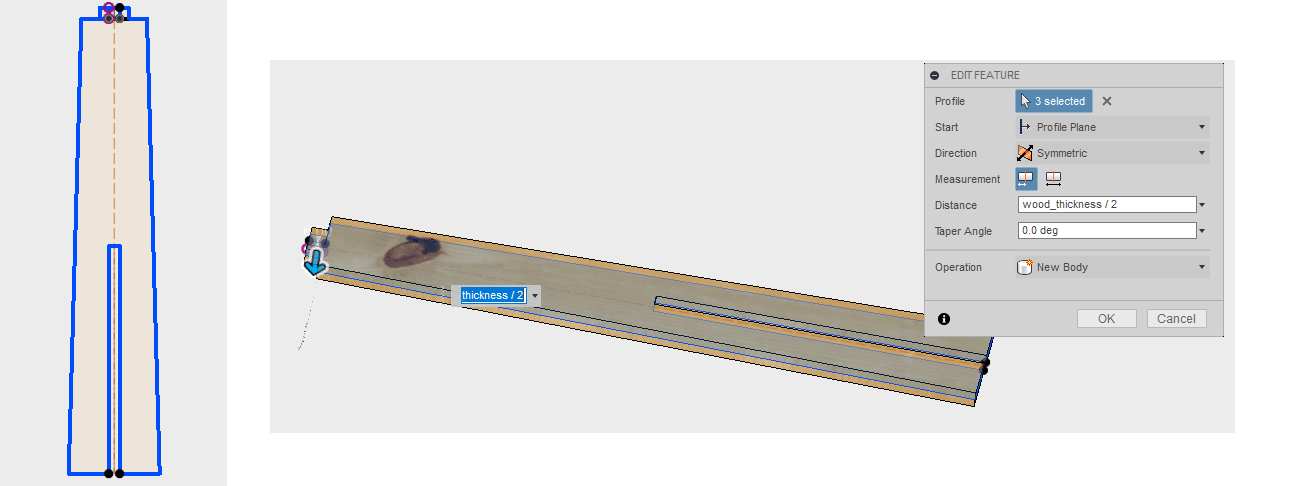
Then I joined the two parts to make the leg and fit it into one of the joints.
And here's how it looks.
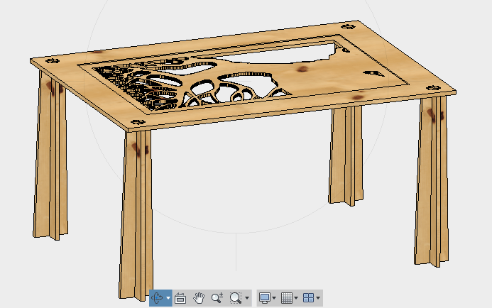
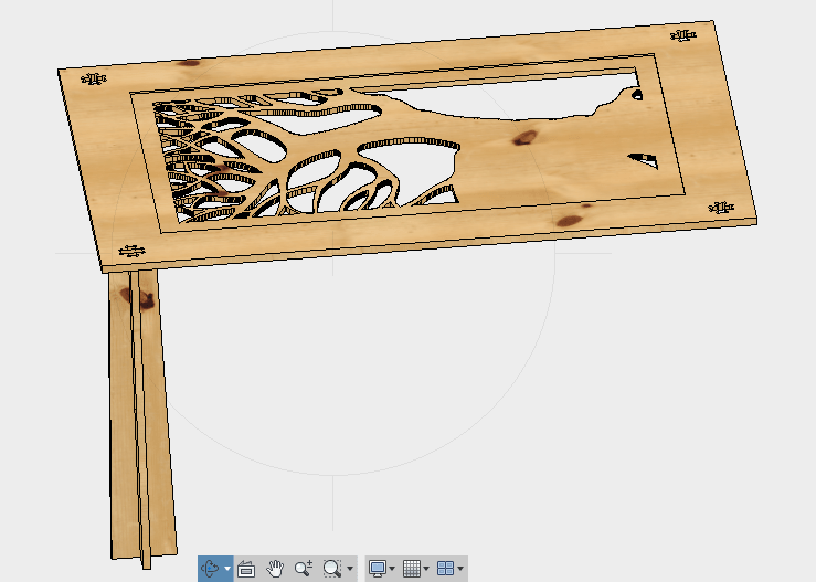
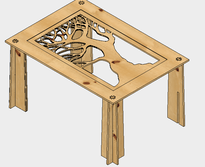
After I showed the design to my instructor, he mentioned that I should make the part of the leg that touches the table top cover as much space as possible to provide extra support so I edited the leg designs.
Now my table looks like this.
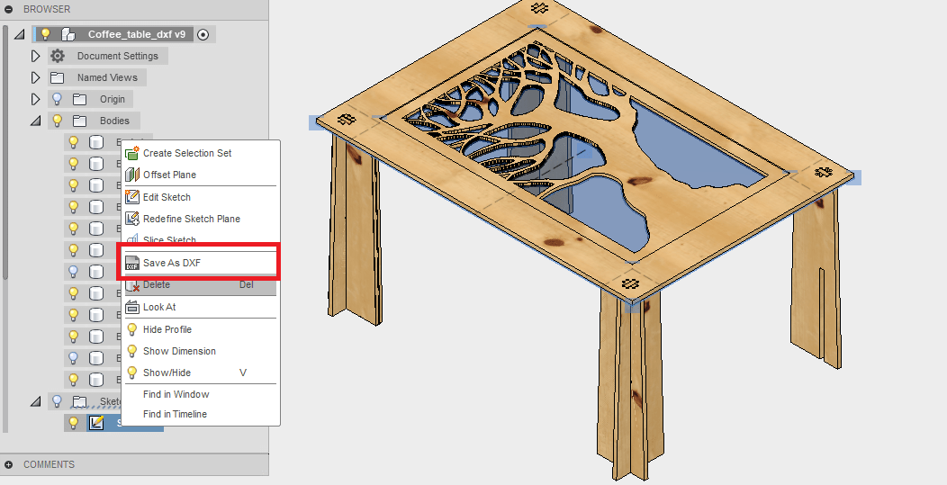
Now the only thing that's left is to export the design into DXF. To do that I went to my sketches, right click on them and save as dxf.
Setting up the file (CAM)
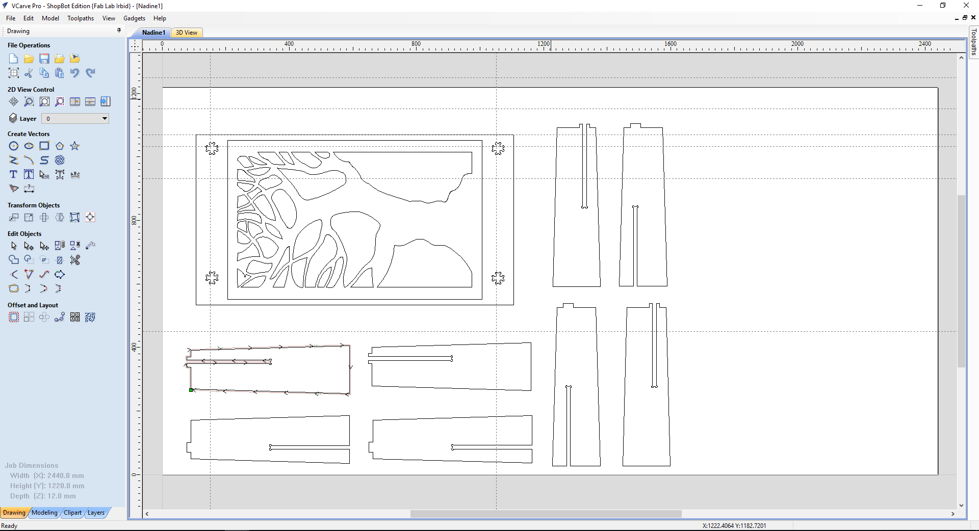
To set up the file to be sent to the CNC machine, we used the ShopBot's software which is the Vcarve Pro.
With this program, you can open your DXF file and set how it will be cut.
The design I made needs to be cut in multiple jobs.
But before diving into to that, we should get to know the machine.
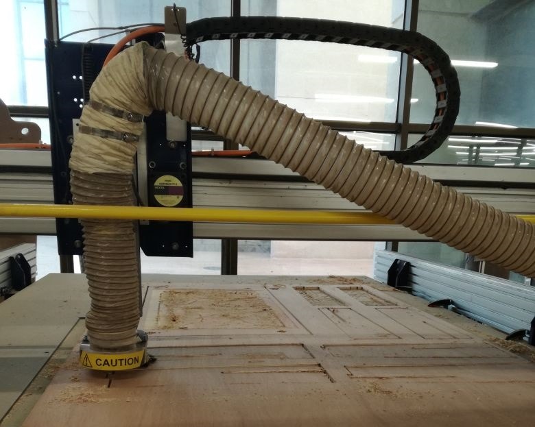
Our CNC machine is called the ShopBot. It has a bed of size 96"x 48".
It has the follwoing parts.
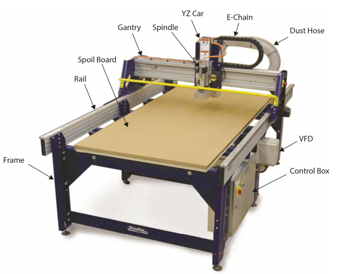
To familiarize yourslef with the machine, read the quick start guide.
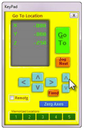
To control the machine and calibrate it, we used a software called ShopBot 3. Using this software, you can set the zeros for the x,y and z axes.
To chose the zero for the x & y, you move the arrows till the spindle is right where you want it and you zero it there.
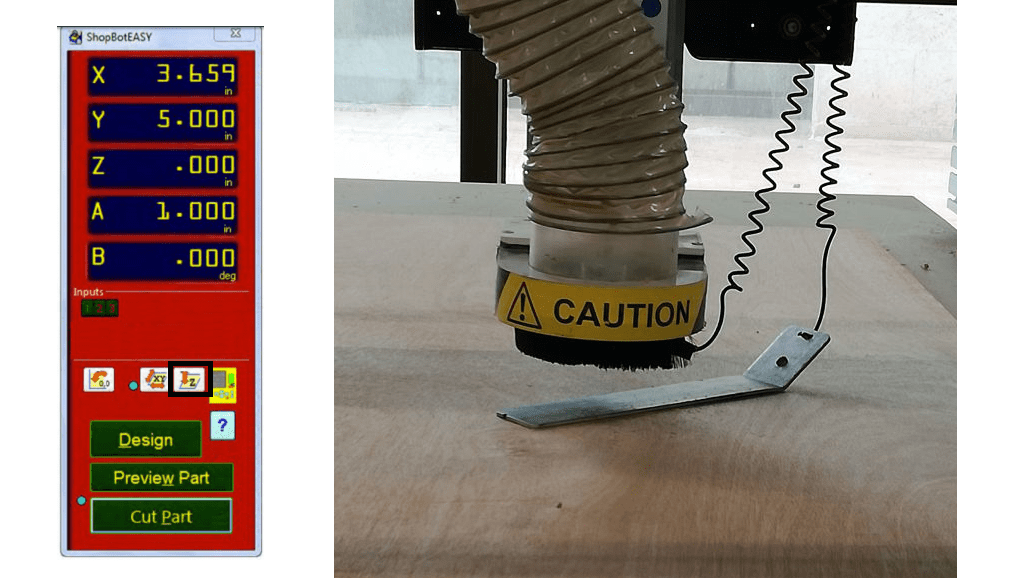
For the z-axis, you press to zero the z, but only before placing the clip on the spindle and the matal plate under the spindle, the machine calibrates the z automatically by slowly lowering the spindle till a short circuit occurs.
Next, you should go back to setting up the file to be cut. I opened my design on vcarve, and started arranging it on the wood plate. I added the thickness of the wood plate and the dimensions of it.
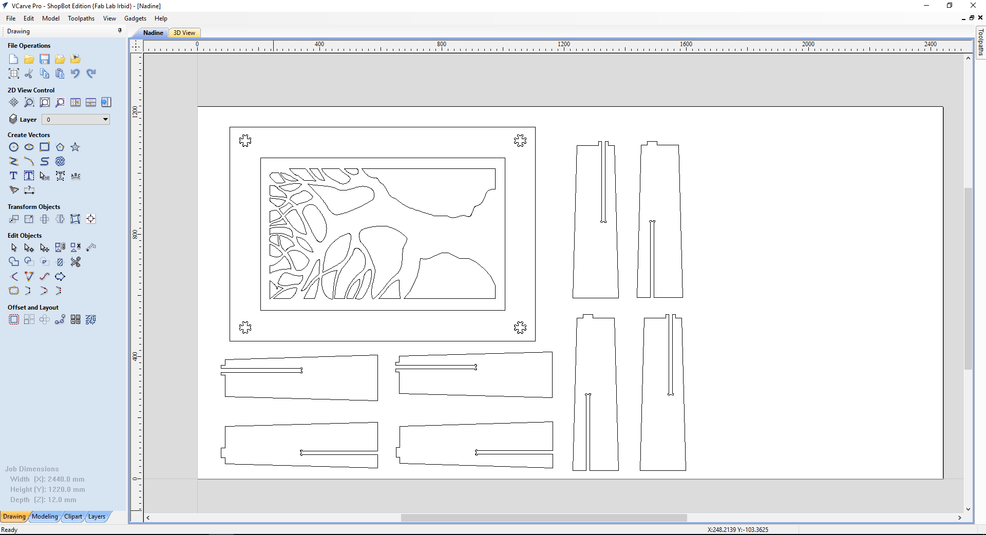
After that, I start choosing which parts to cut. First I started with the pocket.
Pocket means that the cnc will mill the part you chose to a thickness you decide. I decided to use a 3mm acrylic so I set the cut depth to 3mm.
The number of passes is how many times will the tool go through the part to finish the cut.
Since it is only a pocket, I chose a single pass.
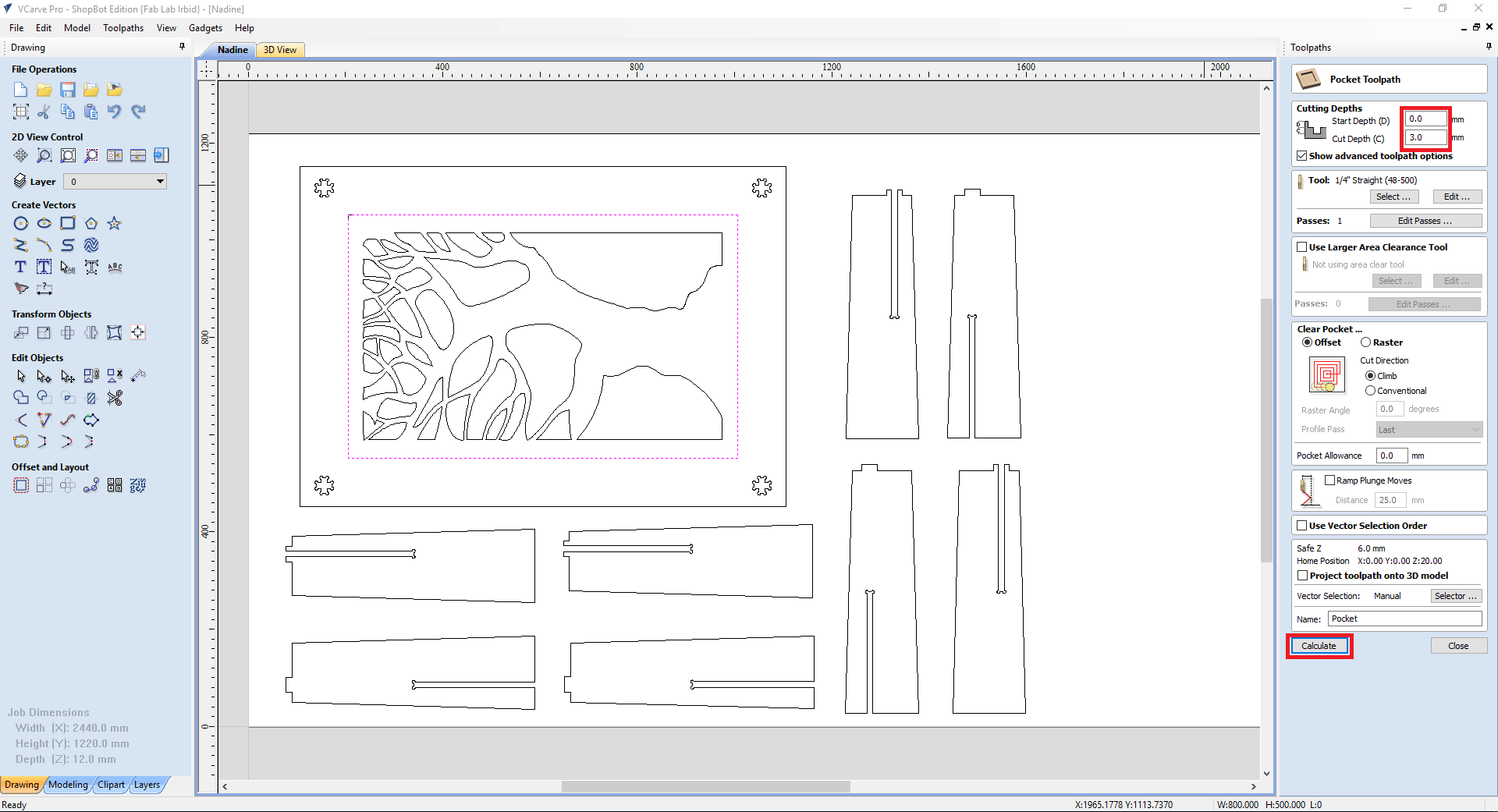
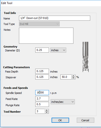
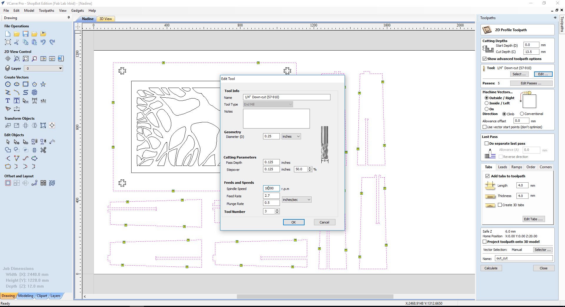
I set the spindle speed to 18000 RPM and the feed rate to 2.7 inch/sec. The drill bit I chose was 1/4" because my design has a little bit of details in it.
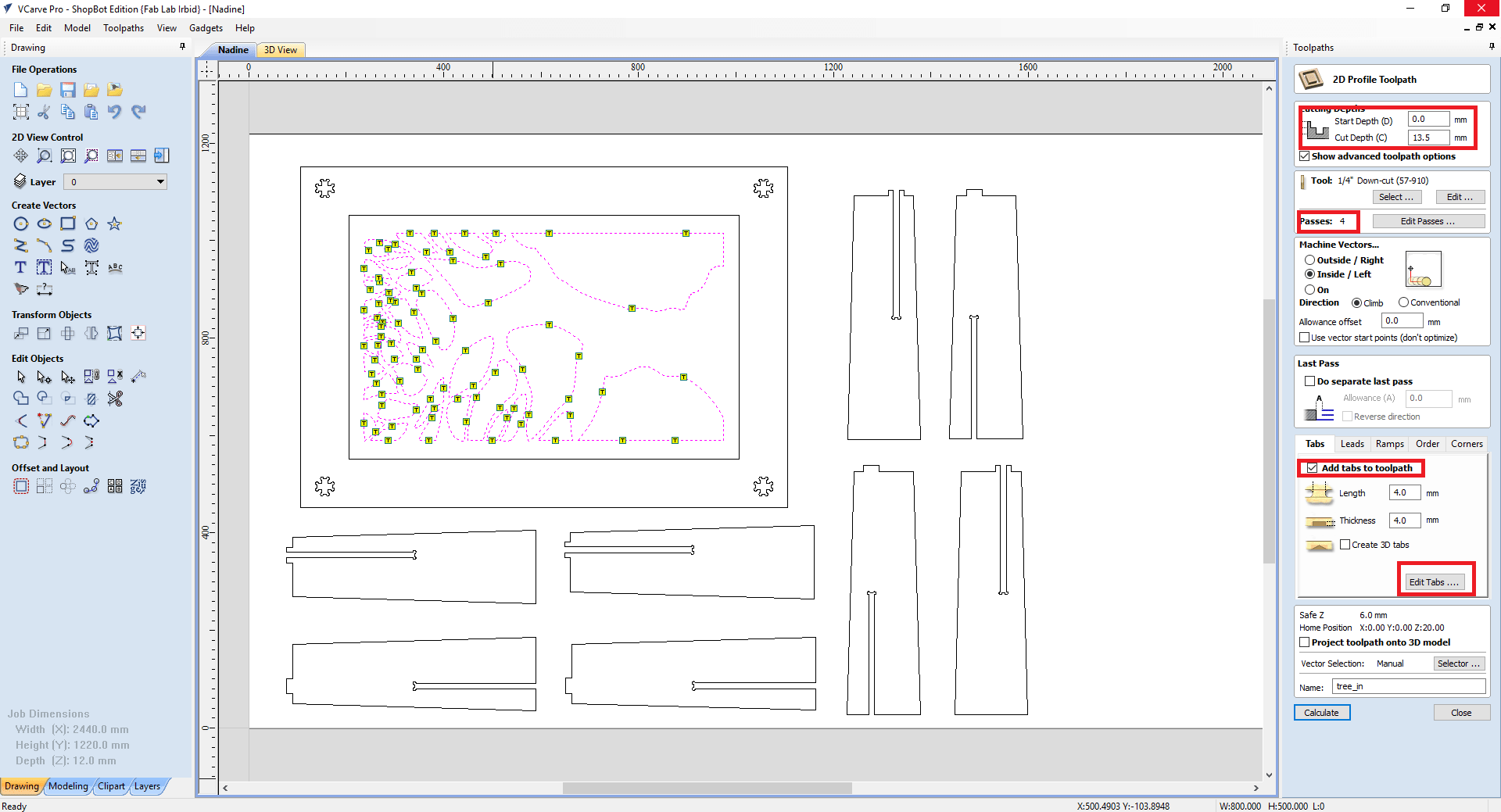
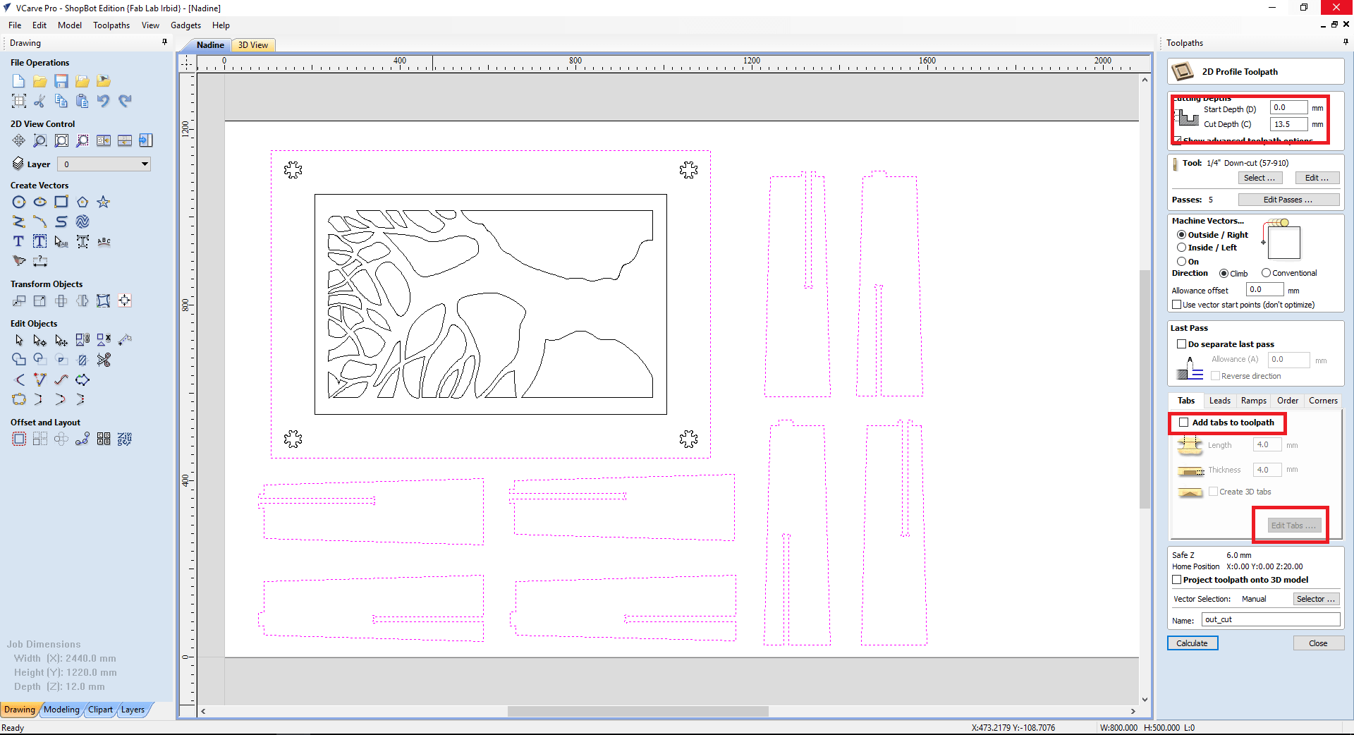
The next job I chose to cut, was the tree. so I chose the parts that I want to be removed. Made the cut to inside cut so I wouldn't lose a lot of material and made the passes to 4 since it will cut through the 12 mm board.
You will notice that I chose the cut depth to be 13.5mm although my wood sheet is 12mm and that's because plywood tend to bend and I want to avoid miss alignments.
I also added tabs. Tabs are parts that are not cut all the way through so it would hold your part in place to avoid it being brokes if it was loose and the spindle pass on it.
Next, I set the joint cut. So I selected the 4 joints and also chose them to be cut all the way through. I also added tabs.
Lastly, I chose all the other parts to be an out cut.
I checked the simulation, and then I saved them as sbp which is the shopBot format.
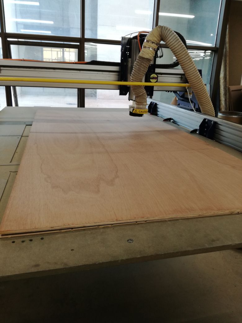
With the help of my coleague, Qusai, we set up the plywood board on the shopBot and set the zero for the z-axis.
Next, I opened the shopbot 3 program and loaded the first file which is the pocket.
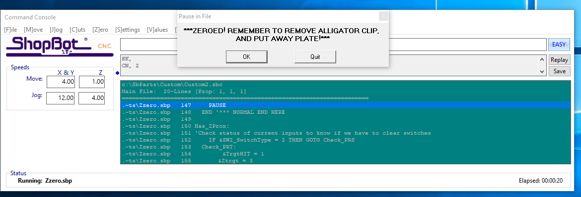
The cool thing about the program is that it gives you small reminders, like have you removed the aligator clip, have you zeroed the z-axis and have you started the spindle. It is important to know that the spindle starts on it's own and not with the stepper motors of the machine.
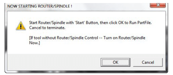
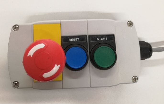
To start the spindle, press the green start button on the control. THIS CONTROL IS YOUR BEST FRIEND FROM NOW ON!!
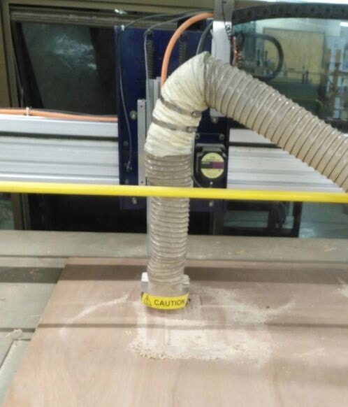
The machine started doing the pocket as seen below.
Then, I launched the tree cut, when it was done I felt like it didn't cut through but since I set the cut depth to 13.5mm and my board is 12mm in thickness, I figured it was only the tabs that is holding it in.
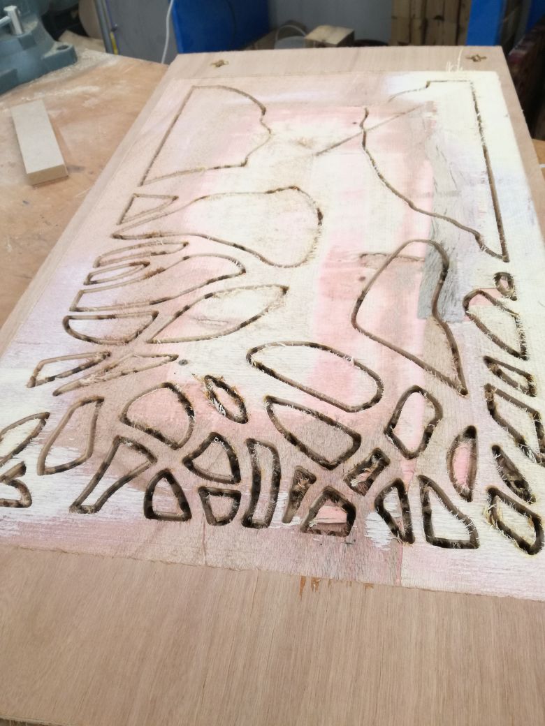
Unrotunately, my fears came to life :(
Next, I launched the joint cuts. And I'm telling you this week just isn't my week! I made the stupid mistake of setting the cut on an outside cut instead of an inside cut and here's the result.
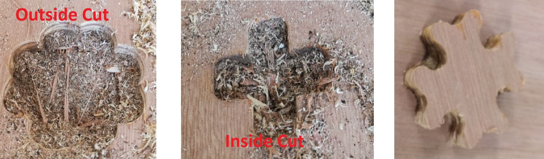
Luckily, I paused to check if everything was cutting fine and discovered the error. So I wouldn't lose the entire board, I went back to the vcarve, moved my joints and made the table smaller.
Then I repeated the cut. After that I launched the final outer cut.
Problems
Other than the mistaken outside cut, there was also a huge miss alignment with the wood. It's either the z-axis wasn't correctly set to zero which is unlikely or the wood was severly bent.
Some parts were completely cut through and some weren't.
to solve the issue of the outer cuts, I repeated the cuts but this time I made the cut depth 15mm. The outer cuts were cut fine after that but I unfortunately couldn't repeat the tree cuts as 15mm means there won't be any tabs and there are a lot of pieces to be but which means we risk some getting loose and hitting the spindle which is dangerous to the people in the wood shop so I decided to do them manually and my colleague Qusai helped me. I really feel like I can handle myself around the wood shop now. It was tiring but fun!
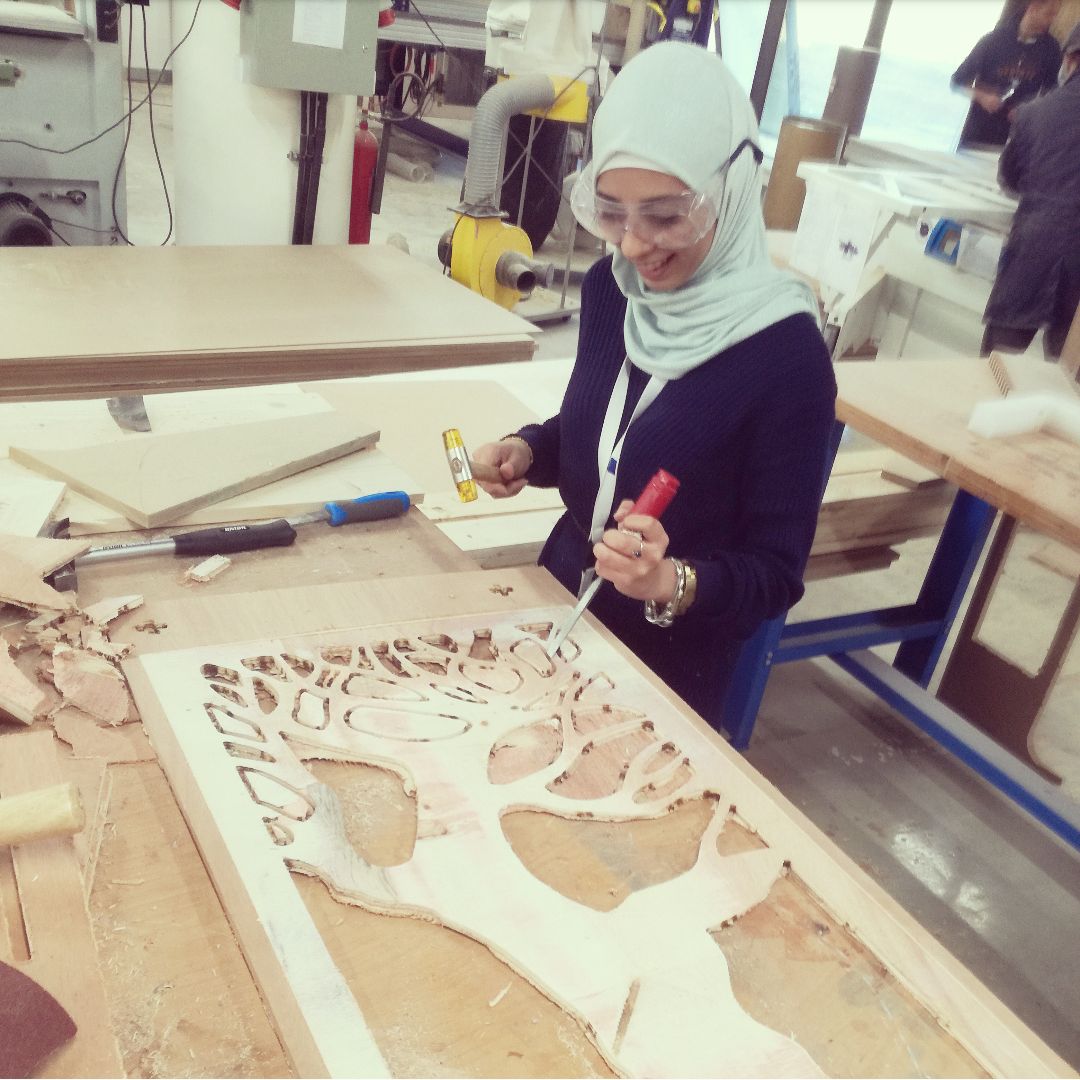
I used a lot filing and sanding to get it to a good finish but it was definitely worth it!
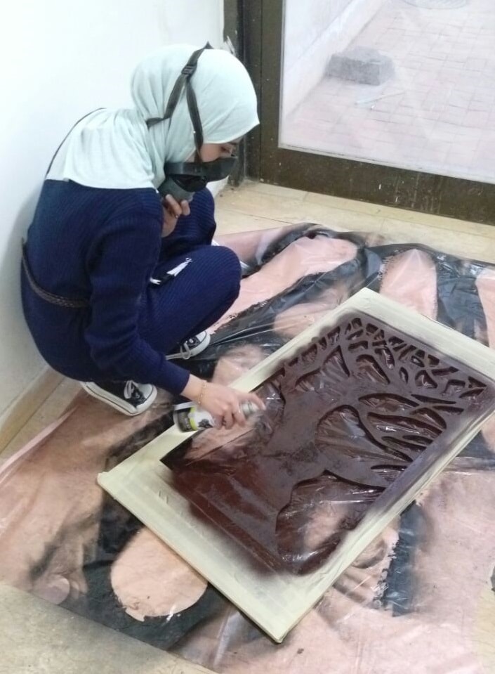
Painting & assembly
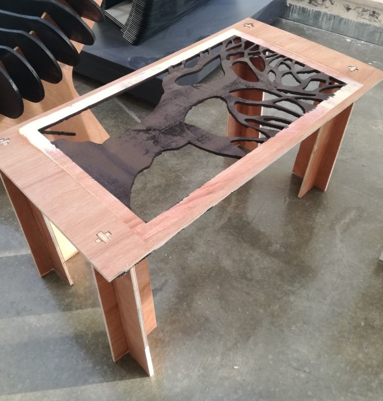
I wanted to paint the tree, to make it stand out, after all we did spend a good 3 hours making it look the way it should have in the first place! So I placed masking tape on the side and used a spray paint to paint it.
For the assembly, a simple filing and a lot of hammering to get the legs to the joints. But it looks good for first time experience in the wood shop!
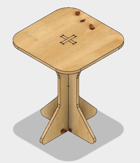
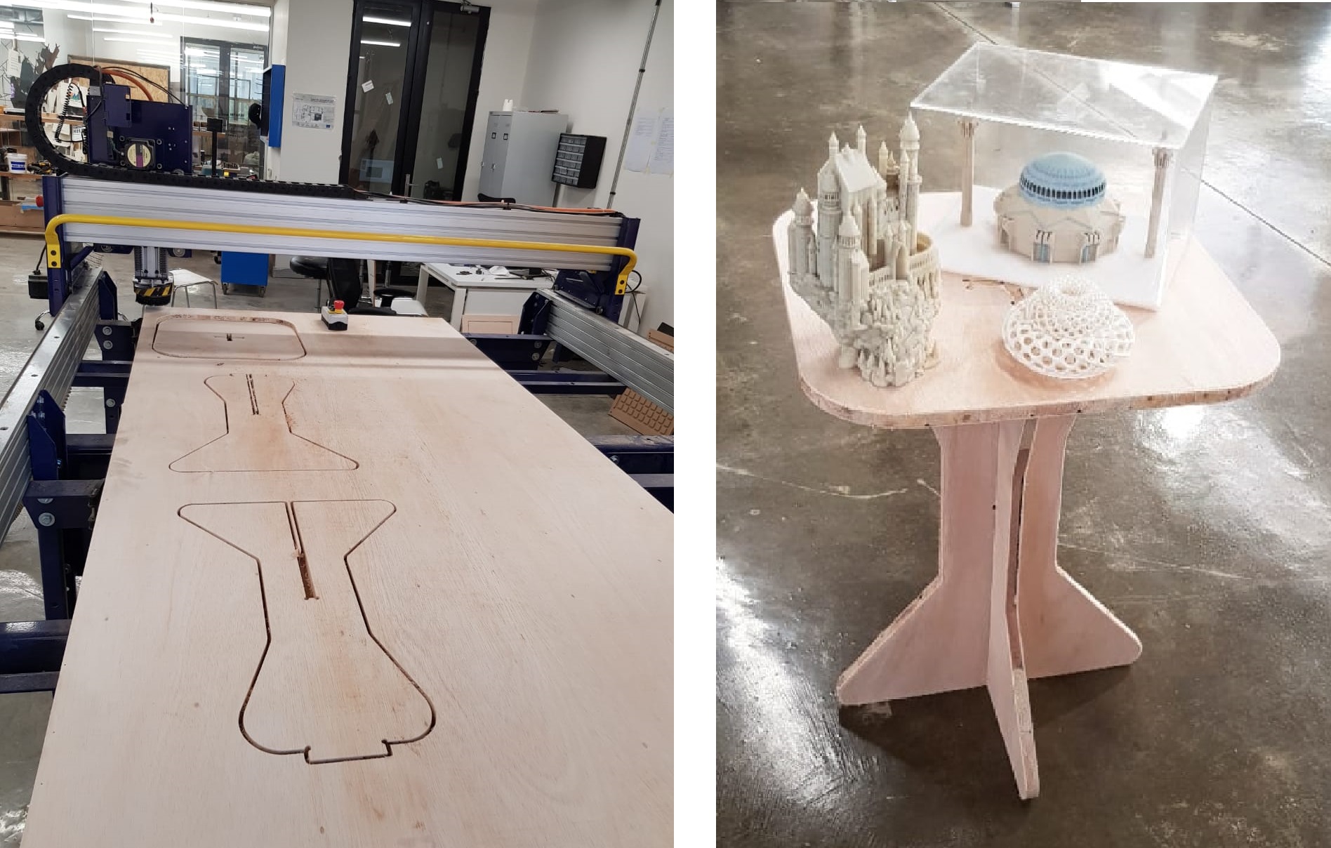
My instructor Dima, didn't like the finishing of the table, so he asked me to recut it but instead of cutting the same thing, I designed a simpler table made of a top part and 2 parts for the legs.
Regarding the settings I used, I cut the table in 2 jobs, one for the inside cut which is the joint on the top of the table and the second for the outer cuts for the legs and the top.
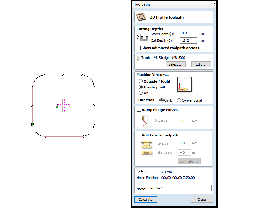
The second job's settings is seen below.
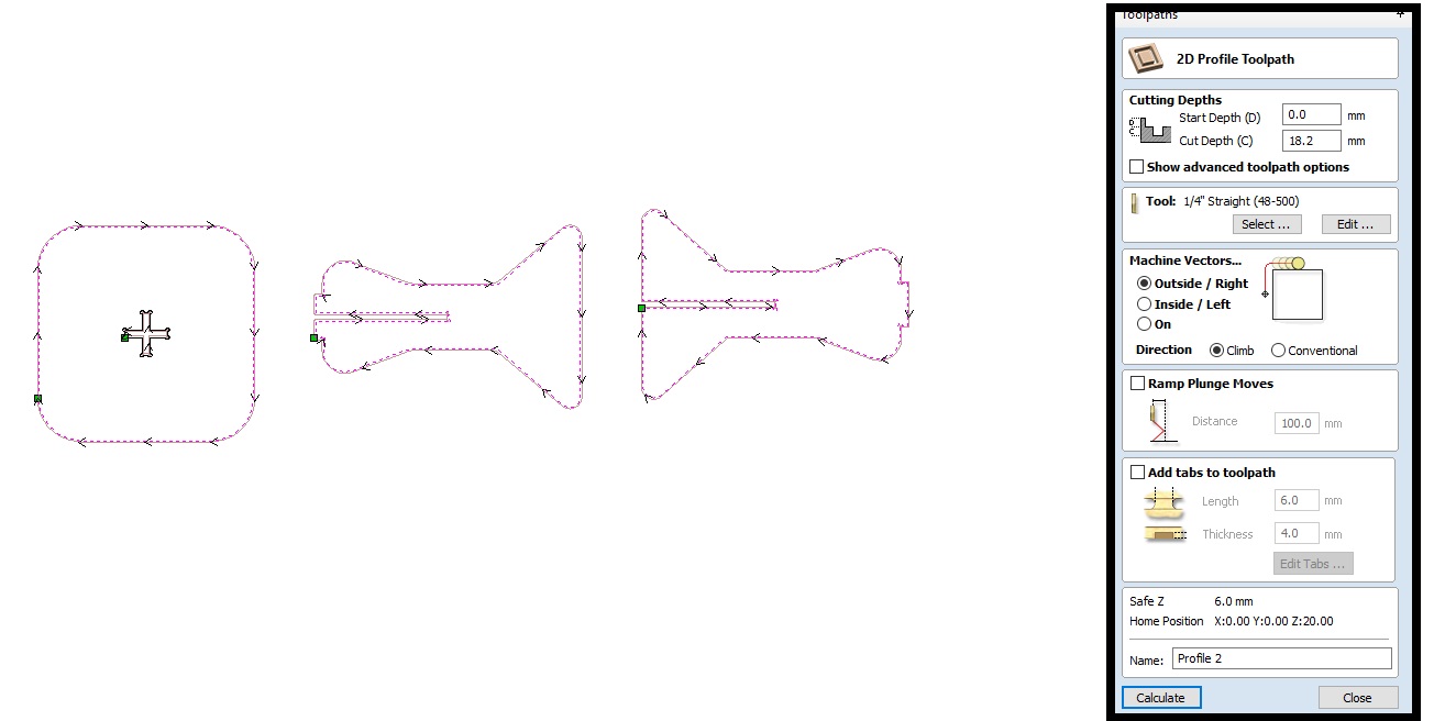
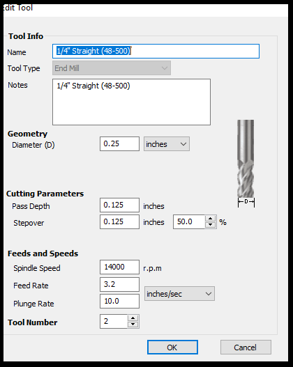
As for the tool I used in the second job, I used 1/4" endmill and I set the settings as seen below.
Here's a photo of the finished cut.
You can download my files here:
