Schematics
I decided to use  Eagle from Autodesk.
In Eagle you have to first create a Schematic for your circuit board. A schematic is basically a layout of the components you will be using and how those components are connected to each other.
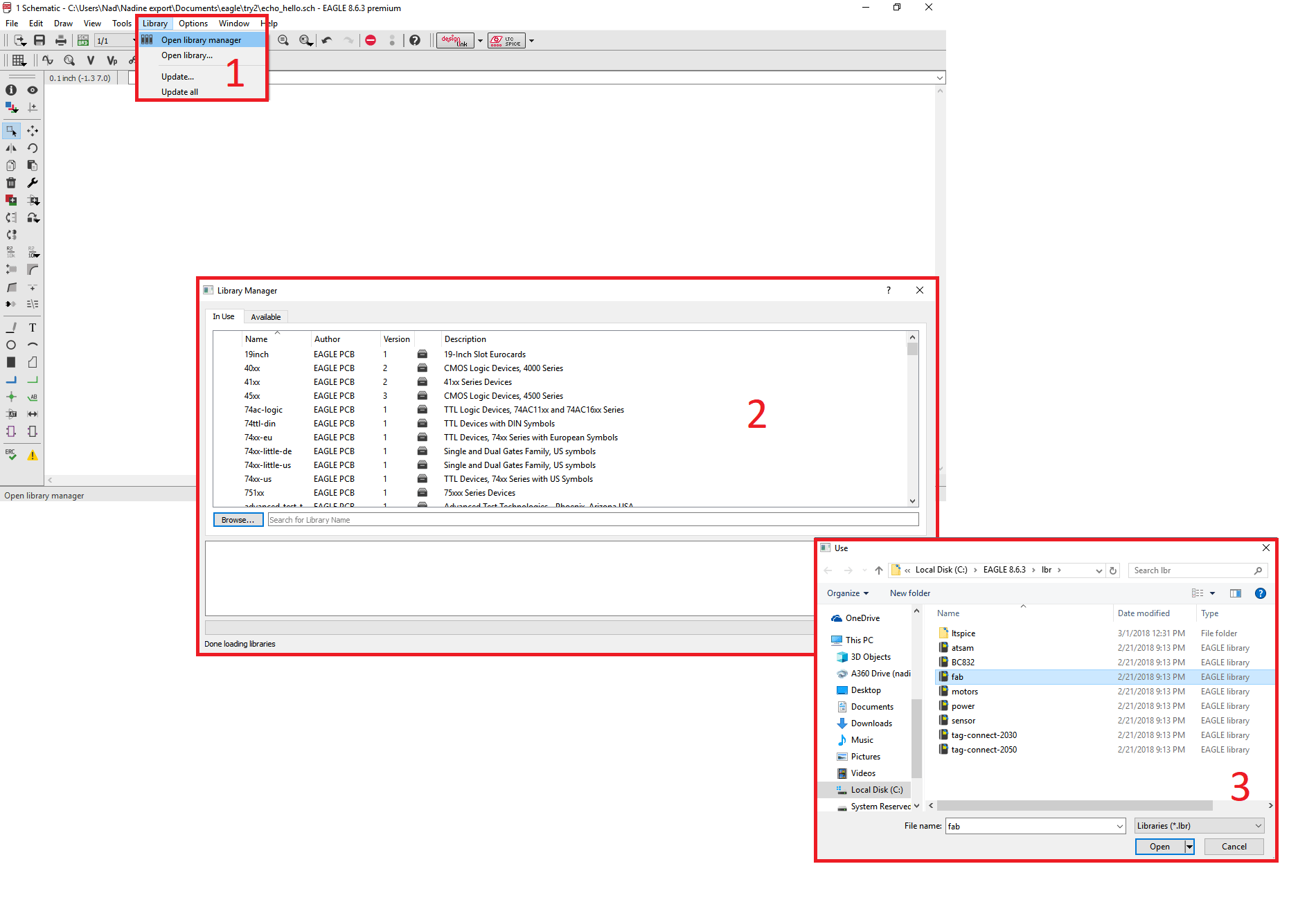
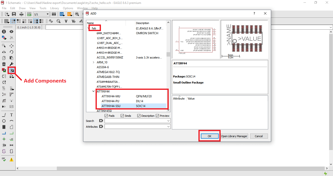
First I downloaded the Fablabs Library and started adding the components I needed.
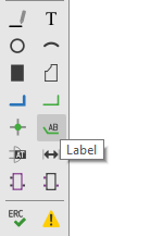
I used a lot of Labels to avoid having wires all over the place which will confuse me.
Following Daniele Ingrassia's Satshakit which is an improved and fabbable , 100% Arduino IDE/libraries compatible board.
I decided to call mine Katara V1.0 since it's the board for my final project. So I first started with the schematics. The arduino uses the Atmega328P. So we first downloaded the library of the component for eagle.
Then I started connecting the pins of the microcontroller to labels as seen below.
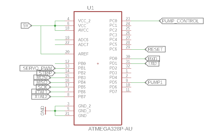
To connect the labels correctly, I refrenced the below seen pinout.
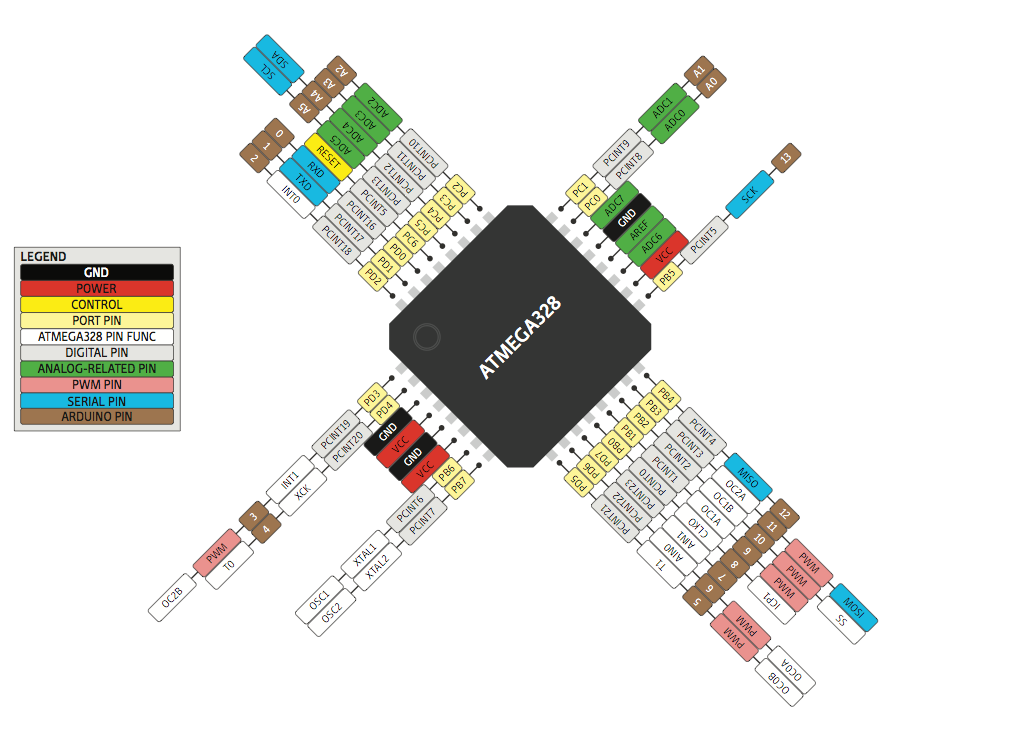
As you can see, this boad is customized for my final project, that's why not all the pins are connected.
I need a pin to control the servo motor's movement and another one to control the pump's voltage that will be controlled using a potentiometer and I need a pin to control the LED strip.
The other pins are programming pins (SCK, MISO, MOSI, RESET) and the communication pins for the Bluetooth.
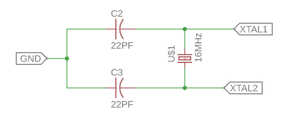
I first started with the Crystal. The crystal I used is the 16MHz although the Atmega 328P can run on up to 20MHz. The recommended capacitance to use is 22PF. The circuit for the Crystal is seen below.
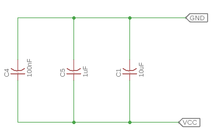
Then I connected other capacitors with values of (100nF, 10uF & 1uF) in parallel and connected to the VCC and the GND. The goal of this circiut is to make the board more stable.
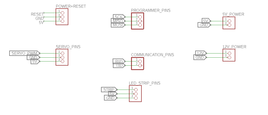
After that, and going back to the pinout, I chose which pins should be connected to pin headers. I chose pins in a way that made connecting them easier while I'm designing the board.
I connected the pins to pin headers as seen below.
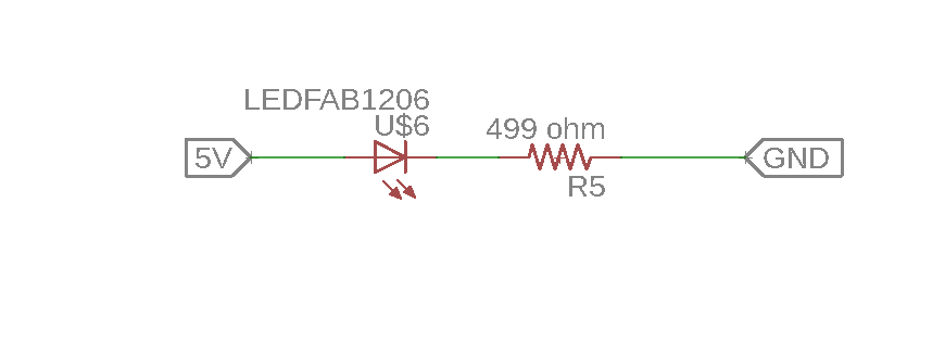
I connected an LED in series with a 440 Ohm resistor between the 5V and the GND to indicate when the board is powered on.
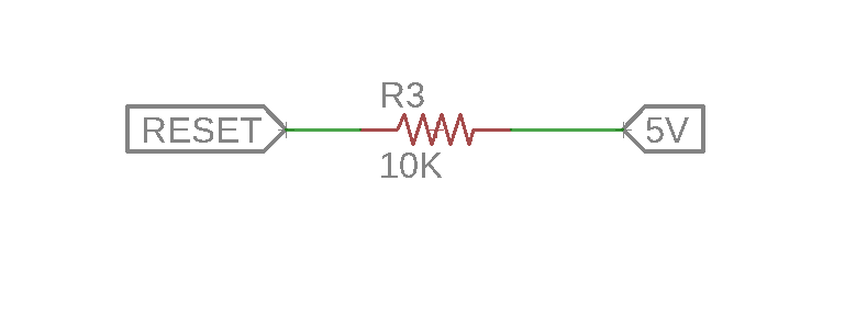
I also connected a pull up resistor with the reset, this is important to be able to program the board.
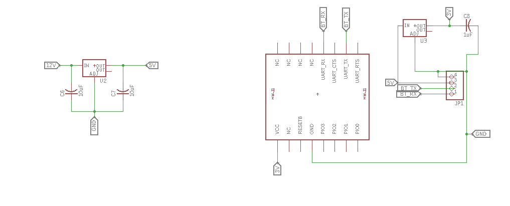
I added 2 voltage regulators. One will regulate the voltage from 12V to 5V since I want to power my system using a power adapter with an output voltage of 12V.
The other voltage regulator, regulates the voltage from 5V to 3.3V to be able to power the on board bluetooth chip as it runs on 3.3V as seen below.
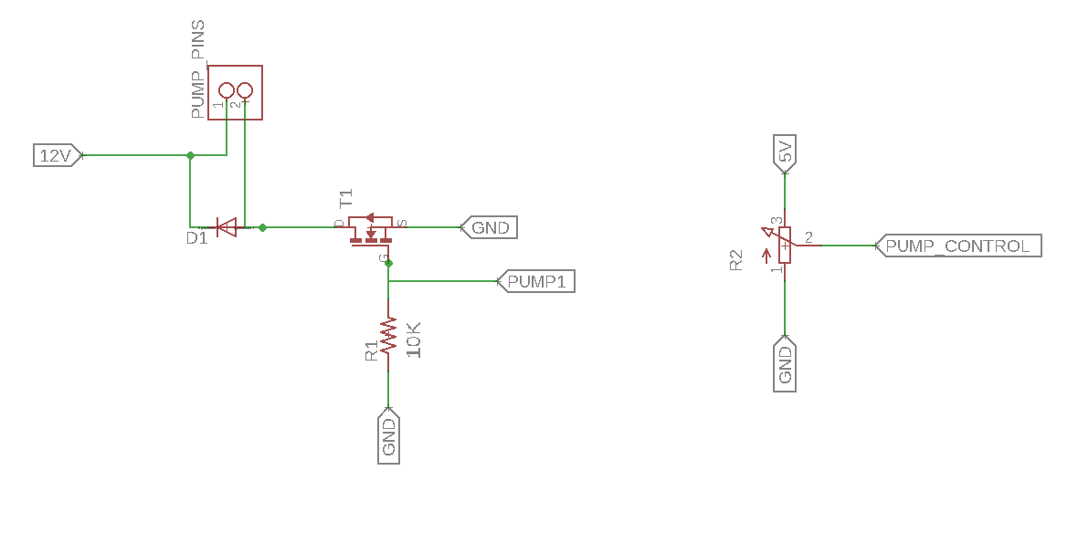
The last thing left, is the pump control. The pump can operate from 5V-12V. To control the strength of pumping, I used a MOSFET and a potentiometer as seen below.
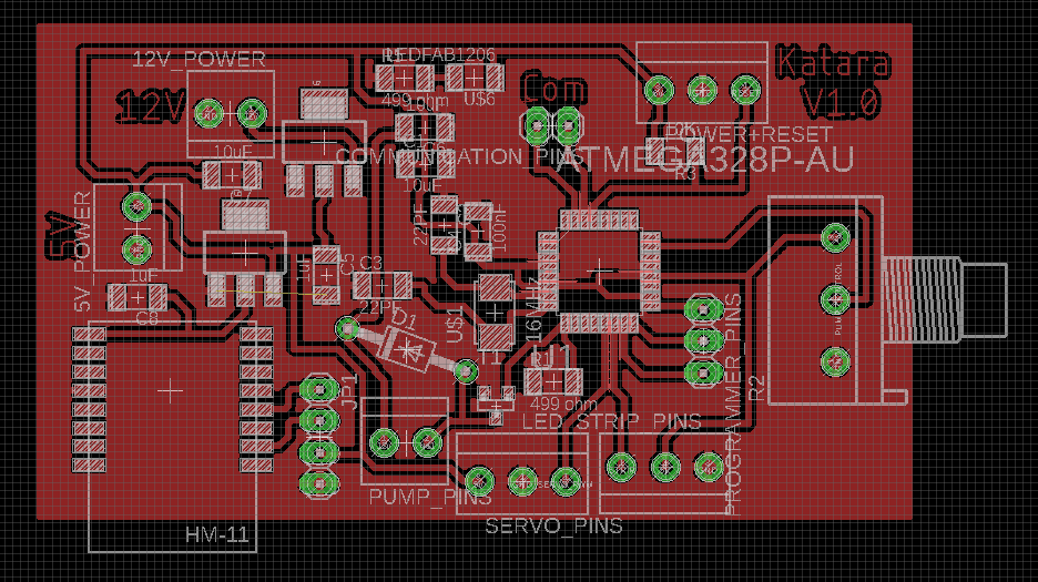
After I checked that my schematics are okay and that I didn't leave anyting I might need out. I moved to the routing process.
Routing wasn't easy! I spent a couple of hours trying to route this baby and I ended up with the below image. I only have one airwire that could be easily solved with a zero ohm resistor!
Milling the Katara V1.0
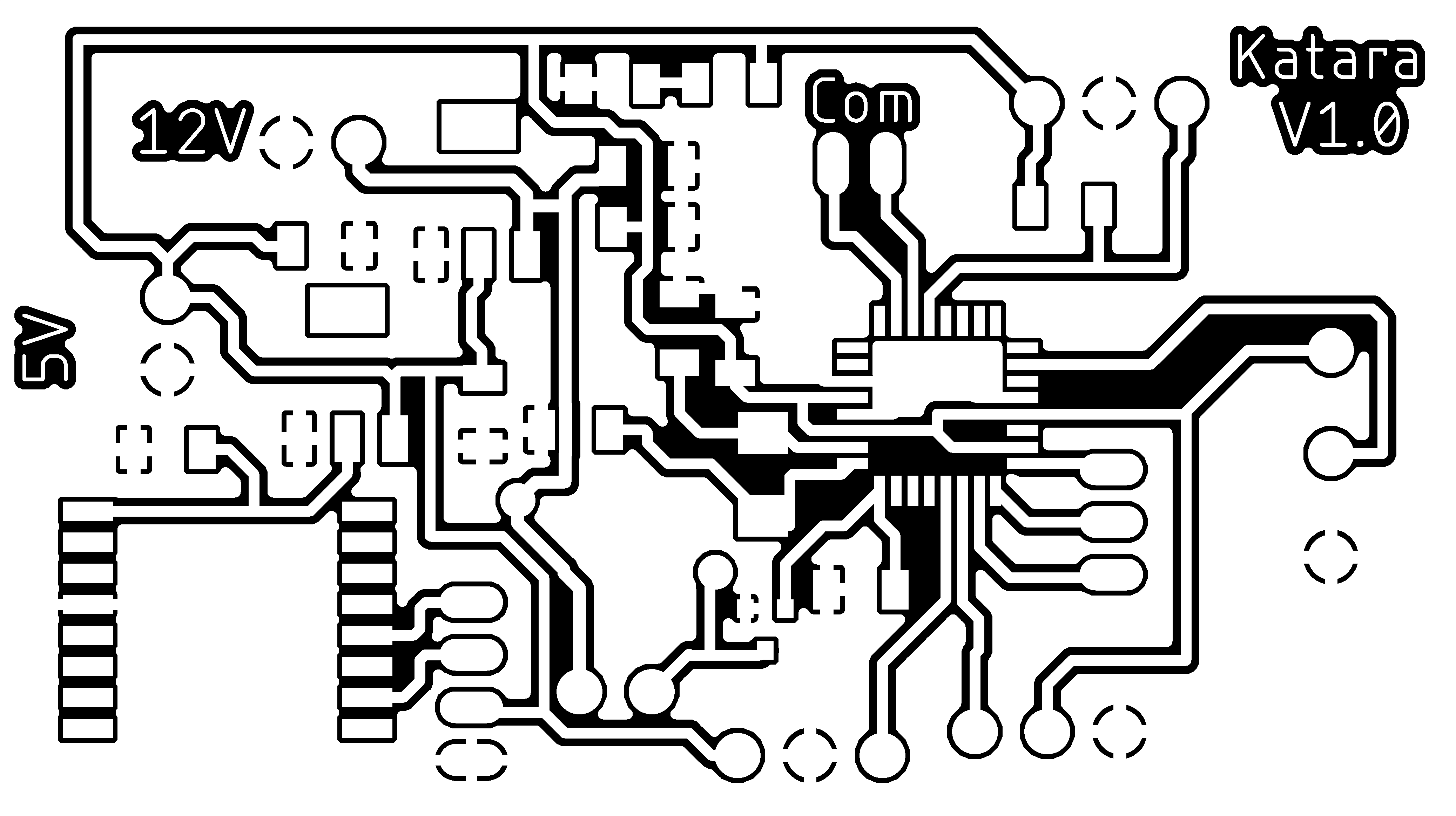
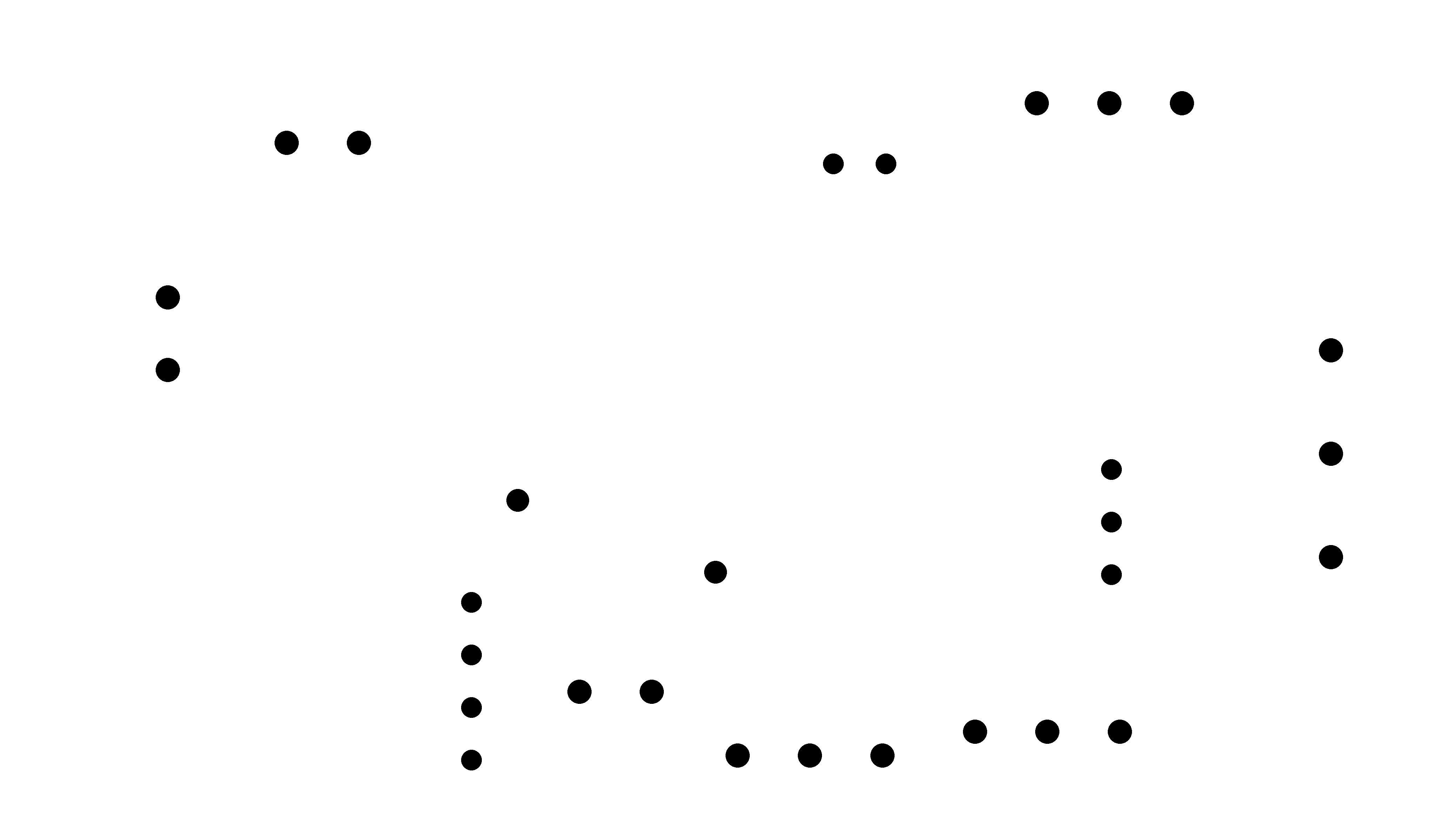
To start the milling process, I exported my design as png. I made 2 exports, one for the traces and another displaying only the pads layer to do the drilling process for the pin headers.
I had to edit the exported pads image to have only the drilling holes as seen below
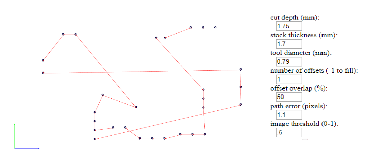
Next, I uploaded the inner traces image to the Fabmodules and set the settings as seen below. The end mill we used to mill this board is a 0.2mm drillbit.
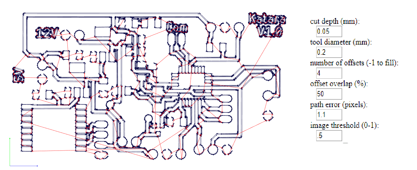
Next, I uploaded the drilling and changed the process to 1/32. The result and settings I used are seen below. I set the speed for the drilling to 0.5mm since it will cut all the way through the PCB Stock (cut depth was set to 1.75mm).
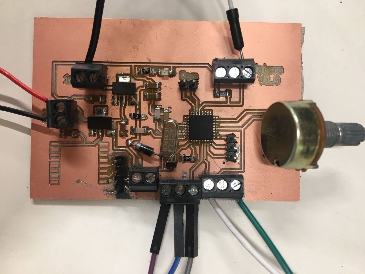
I forgot to take a photo before soldering the components which was a hassle but here's how my finished board looks like!
Before I connected the Bluetooth, the pump, the servo and the LED Strip, I had to make sure that my board is actually regulating the input voltage from 12V to 5V and 3.3V as seen in the below video.
Now it's ready to be put in operation!
You can download the schematic and board HERE.
