Interface & Application Programming Week
This week we had to create interfaces to our boards using serial communication. I decided to use both Python and Processing to do that.
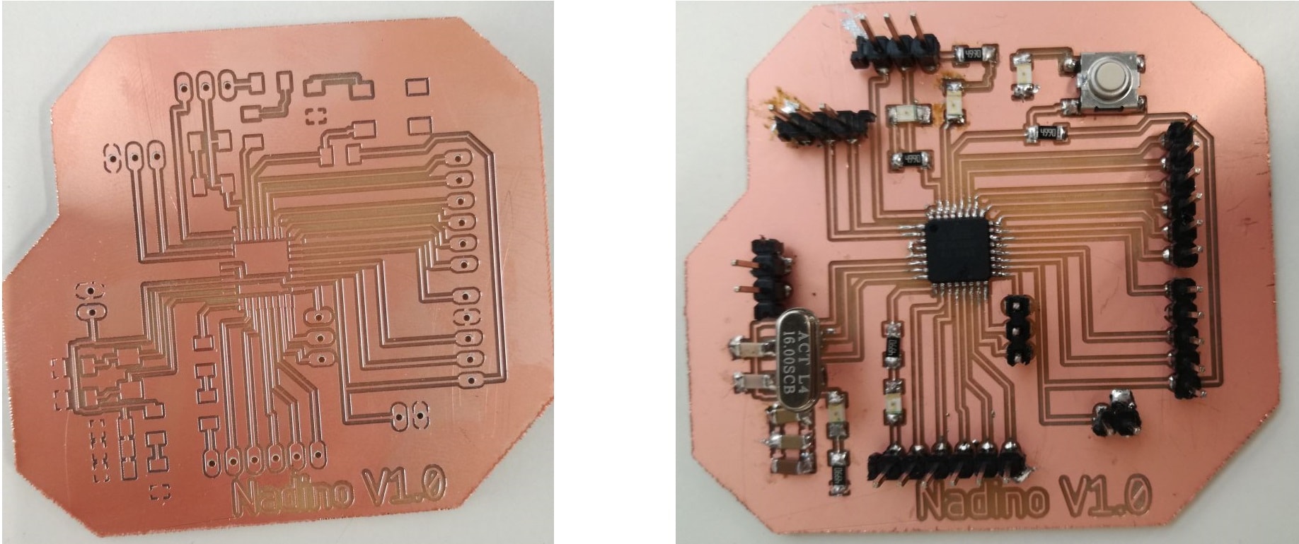
The board I used is my Nadino Board that I built in Electronic Design Week.
I first decided to use Python. I decided to do something simple for starters. I wanted to make an interface with 3 buttons that can control an LED on my board. One to light the LED, the other to turn it off and the last one to blink it.
Python Interface
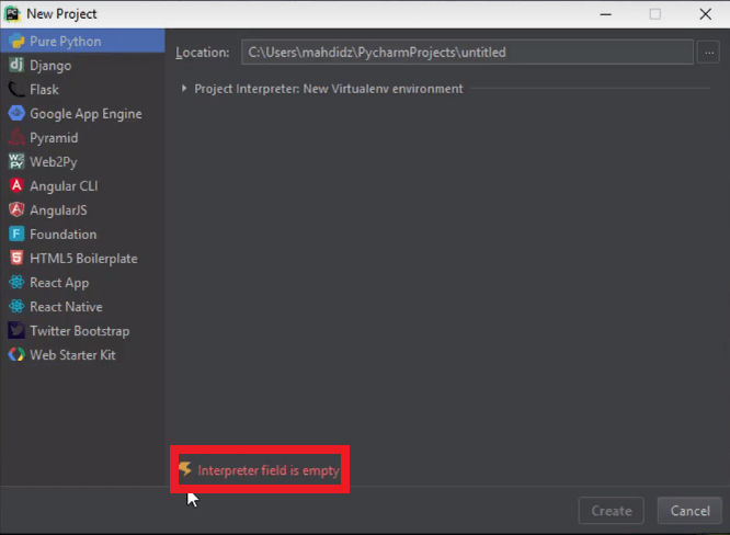
I decided to use python on a Windows operating system, to do that I had to install an IDE, I chose to work with PyCharm.
Downloading an IDE is not enough to start programming with Python on a windows device, you also have to download the interpreter which Python, surprize!
If you don't do that, you'll end up with a missing interpreter file error when trying to create a new project.
I downloaded Python 3.6.5.
The IDE is pretty easy to use, and my code is shown below.
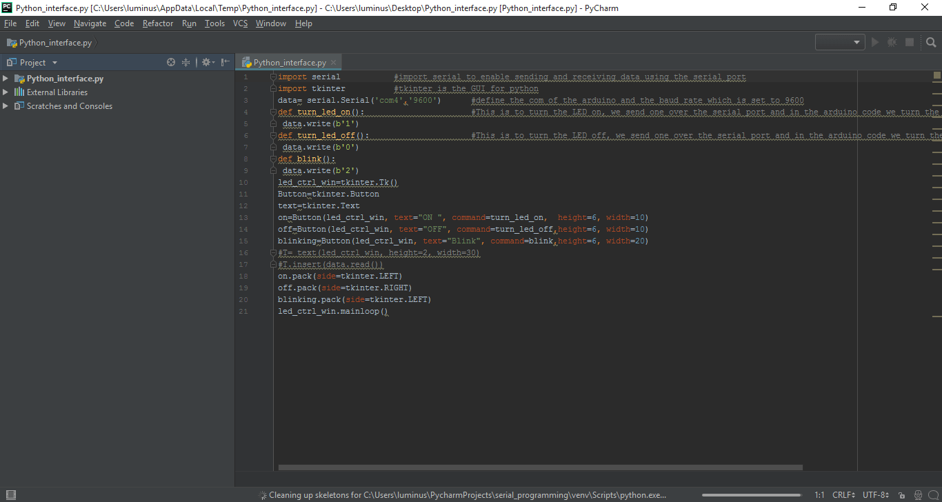
The code is pretty simple, I imported the serial library to be able to use the serial port. Another library that I imported is the tkinter library which is the standard Python interface to the Tk GUI toolkit. I used it to draw my interface. My interface is quite simple, it is 3 buttons, when each is pressed it sends different data over the serial port which will tell the arduino what to do.
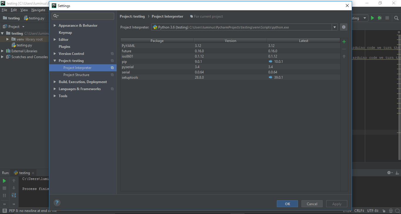
An important thing to note is that you need to install the pyserial library or package. To do that press CTRL + ALT + S this will open up a window, under project interpreter choose the libraries to install. I only choose pyserial but a bunch were installed, I guess they come in a bulk!
My python code is shown below:
                Python Code
import serial           #import serial to enable sending and receiving data using the serial port
import tkinter          #tkinter is the GUI for python
data= serial.Serial('com4','9600')      #define the com of the arduino and the baud rate which is set to 9600
def turn_led_on():                      #This is to turn the LED on, we send one over the serial port and in the arduino code we turn the led on using digitalWrite
 data.write(b'1')
def turn_led_off():                     #This is to turn the LED off, we send one over the serial port and in the arduino code we turn the led off using digitalWrite
 data.write(b'0')
def blink():
 data.write(b'2')
led_ctrl_win=tkinter.Tk()
Button=tkinter.Button
text=tkinter.Text
on=Button(led_ctrl_win, text="ON ", command=turn_led_on,  height=6, width=10)
off=Button(led_ctrl_win, text="OFF", command=turn_led_off,height=6, width=10)
blinking=Button(led_ctrl_win, text="Blink", command=blink,height=6, width=20)
#T= text(led_ctrl_win, height=2, width=30)
#T.insert(data.read())
on.pack(side=tkinter.LEFT)
off.pack(side=tkinter.RIGHT)
blinking.pack(side=tkinter.LEFT)
led_ctrl_win.mainloop()
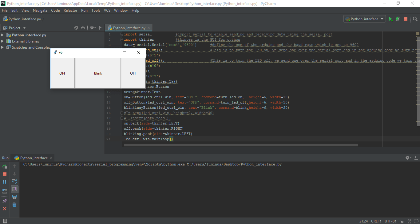
The interface is shown in the below image.
On the Nadino Board's side, it is also pretty simple. Depending on the received data the arduino does a certain action which is either to turn the LED ON, OFF or Blink it.
                Arduino LED Code

#define led 5
void setup() {
  // put your setup code here, to run once:
Serial.begin(9600);
pinMode(led,OUTPUT);
}

void loop() {
  // put your main code here, to run repeatedly:
          int data=Serial.read();
          switch (data){
          case '0':
                digitalWrite(led,LOW);
                break;

           case '1':
                digitalWrite(led,HIGH);
                break;

          case '2':
         blink();


}
}

void blink(){
   for(int x=0; x<5; x++){
   digitalWrite(led,LOW);
   delay(500);
   digitalWrite(led,HIGH);
   delay(500);
   digitalWrite(led,LOW);
}
The below video shows what happens when I run the code.
Interfacing with Processing
Processing is a flexible software sketchbook and a language for learning how to code within the context of the visual arts. I used it to display live sensor data on a graph, it gives visual representation of what is actually happening.
I downloaded Prcoessing for Windows before getting started.
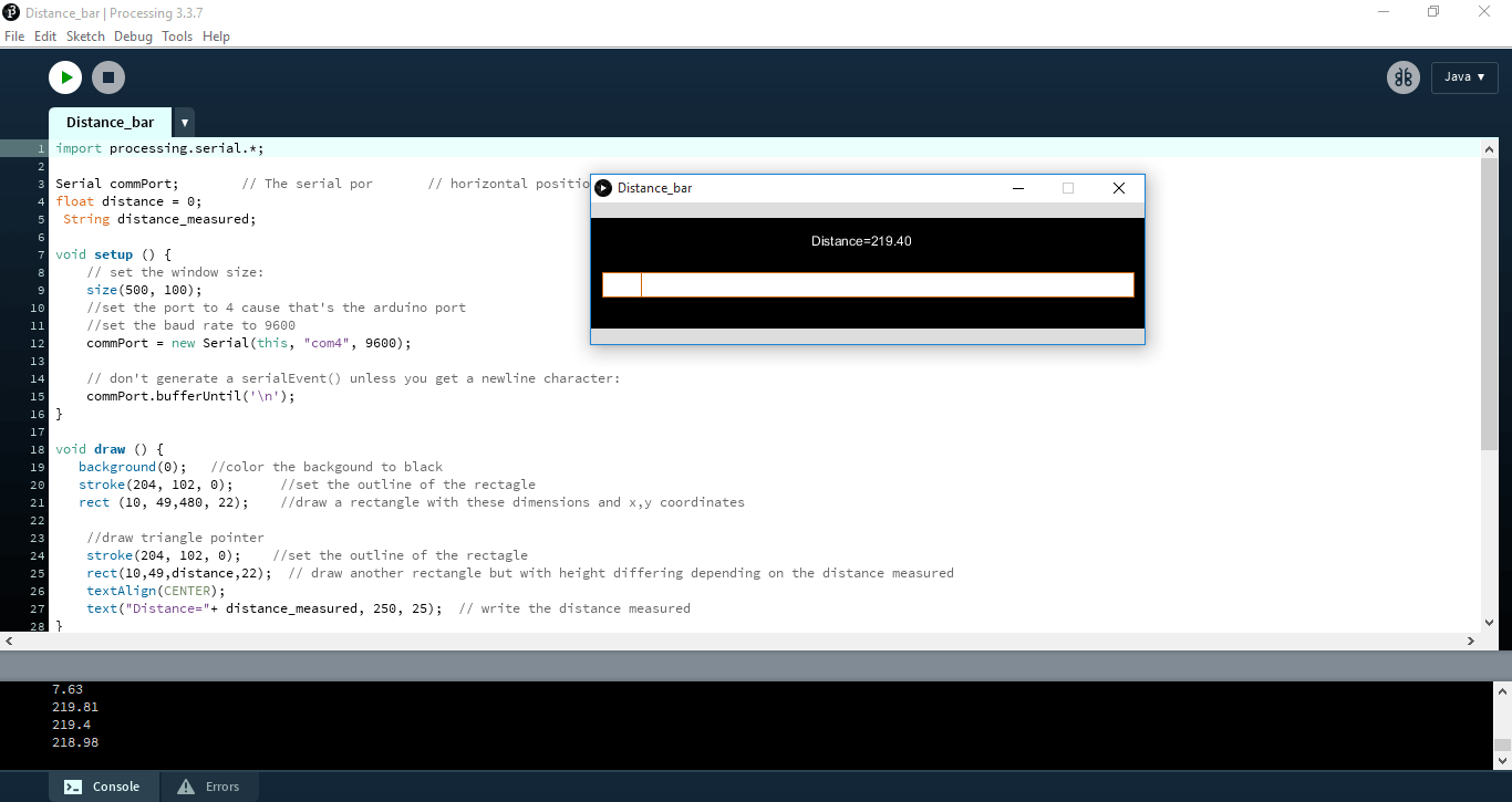
I want to display the readings of an ultrasonic sensor on a bar.
It actually took me a while to understand how everything works. I imported the serail library to enable using the serial port then defined the port I will be using and the baud rate for the communication.
After that, I defined a funtion that will receive data over the serial port kinda like an interrupt. the data received is then displayed using a bar.
To draw the bar, I drew 2 rectangles, the first is fixed and the other changes width based on the reading of the ultrasonic sensor.
The code is shown below.
                Processing Code
import processing.serial.*;

Serial commPort;        // The serial por       // horizontal position of the graph
float distance = 0;
 String distance_measured;

void setup () {
    // set the window size:
    size(500, 100);
    //set the port to 4 cause that's the arduino port
    //set the baud rate to 9600
    commPort = new Serial(this, "com4", 9600);

    // don't generate a serialEvent() unless you get a newline character:
    commPort.bufferUntil('\n');
}

void draw () {
   background(0);   //color the backgound to black
   stroke(204, 102, 0);      //set the outline of the rectagle
   rect (10, 49,480, 22);    //draw a rectangle with these dimensions and x,y coordinates

    //draw triangle pointer
    stroke(204, 102, 0);    //set the outline of the rectagle
    rect(10,49,distance,22);  // draw another rectangle but with height differing depending on the distance measured
    textAlign(CENTER);
    text("Distance="+ distance_measured, 250, 25);  // write the distance measured
}

void serialEvent (Serial commPort) {
    // get the ASCII string:
    distance_measured = commPort.readStringUntil('\n');

    if (distance_measured != null) {
      // trim off any whitespace:
      distance_measured = trim(distance_measured);
      // convert to an int and map to the screen height:
      distance = float(distance_measured);
      println(distance);
      distance = map(distance, 0, 5000, 15, 480); // map the distance measured depending on the size of the rectangle I drew
    }
}
The Nadino's side of things is pretty simple, it just reads the distance using the trig and echo pins of the ultrasonic sensor and sends the distance over the serial port.
                Ultrasonic Sensor Arduino Code
#define trigger 8
#define echo 7
long timeNeeded;
float distance;


void setup() {
  // Open serial communications and wait for port to open:
  Serial.begin(9600);
    ; // wait for serial port to connect. Needed for native USB port only
    pinMode(trigger,OUTPUT);
    pinMode(echo,INPUT);
}

void loop() { // run over and over
      digitalWrite(trigger,LOW);
      delayMicroseconds(2);
      digitalWrite(trigger, HIGH);
      delayMicroseconds(10);
      digitalWrite(trigger, LOW);
      timeNeeded = pulseIn(echo, HIGH);
      distance= timeNeeded * 0.034/2;
      Serial.println(distance);
      delay(1000);
}
When I run the processing code, here's how the interface looks.
The below video shows how the bar changes according to the reading of the ultrasonic sensor.
Problems this week?!
This week, I made a really stupid mistake with Python, I downloaded the IDE, installed it and when I wanted to create a new project I got a Interpreter Field is Empty error and it turned out that it was because I am working on a windows computer and I have to download Python as well not only an IDE. SO SMART NADINE!!
You can download my files here.
